Installation instruction - WindowMaster
Installation instruction - WindowMaster
Installation instruction - WindowMaster

Create successful ePaper yourself
Turn your PDF publications into a flip-book with our unique Google optimized e-Paper software.
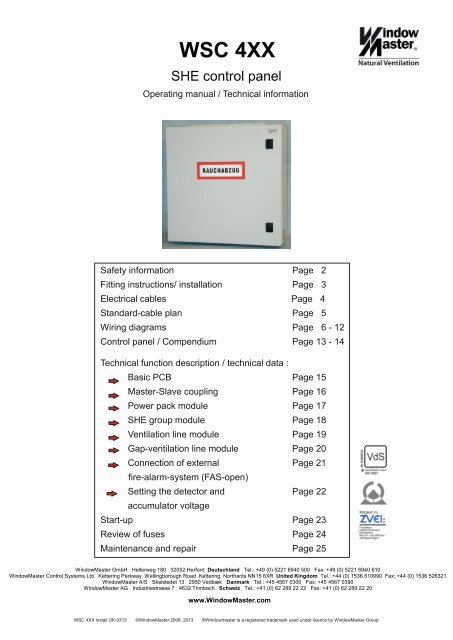
WSC 4XX<br />
SHE control panel<br />
Operating manual / Technical information<br />
Safety information Page 2<br />
Fitting <strong>instruction</strong>s/ installation Page 3<br />
Electrical cables Page 4<br />
Standard-cable plan Page 5<br />
Wiring diagrams Page 6 - 12<br />
Control panel / Compendium Page 13 - 14<br />
Technical function description / technical data :<br />
Basic PCB Page 15<br />
Master-Slave coupling Page 16<br />
Power pack module Page 17<br />
SHE group module Page 18<br />
Ventilation line module Page 19<br />
Gap-ventilation line module Page 20<br />
Connection of external Page 21<br />
fire-alarm-system (FAS-open)<br />
Setting the detector and Page 22<br />
accumulator voltage<br />
Start-up Page 23<br />
Review of fuses Page 24<br />
Maintenance and repair Page 25<br />
Mitglied im<br />
Fachkreis<br />
elektromotorisch<br />
betriebene<br />
Rauch- und Wärmeabzugsanlagen<br />
<strong>WindowMaster</strong> GmbH Hellerweg 180 32052 Herford Deutschland Tel.: +49 (0) 5221 6940 500 Fax: +49 (0) 5221 6940 610<br />
<strong>WindowMaster</strong> Control Systems Ltd. Kettering Parkway Wellingborough Road Kettering Northants NN15 6XR United Kingdom Tel.: +44 (0) 1536 510990 Fax: +44 (0) 1536 526321<br />
<strong>WindowMaster</strong> A/S Skelstedet 13 2950 Vedbæk Danmark Tel.: +45 4567 0300 Fax: +45 4567 0390<br />
<strong>WindowMaster</strong> AG Industriestrasse 7 4632 Trimbach Schweiz Tel.: +41 (0) 62 289 22 22 Fax: +41 (0) 62 289 22 20<br />
www.<strong>WindowMaster</strong>.com<br />
WSC 4XX install UK-0313 ©<strong>WindowMaster</strong> 2006, 2013 ®Windowmaster is a registered trademark used under licence by <strong>WindowMaster</strong> Group
Safety information<br />
Attention!<br />
Adherence to the following information is mandatory:<br />
Only allow correspondingly trained, qualified<br />
and skilled personnel to carry out installation work.<br />
Reliable operation and the avoidance of<br />
damage and hazards is only guaranteed if<br />
installation and settings are carried out carefully<br />
in accordance with these <strong>instruction</strong>s.<br />
Check the technical data on the system plate.<br />
Hazards to persons ensuing from flaps and<br />
wings operated by electric motors.<br />
The forces occurring in the automatic mode can<br />
be such that parts of the body could get crushed.<br />
When opened, actuators could protrude into the<br />
room.<br />
For this reason, measures have to be taken<br />
prior to starting up the actuators which exclude<br />
the danger of injury.<br />
With wings tilting inwards or outwards, the wing<br />
must be protected from hinging down once the<br />
actuator is unhooked (e.g. for window cleaning).<br />
For safety reasons we recommend the use of<br />
catching shears.<br />
In the event that wings or flaps are subjected to<br />
high wind loads, we recommend to connect the<br />
central control unit to a wind detector which will<br />
automatically close the flaps.<br />
The fastening methods are exclusively intended<br />
for the intended use for which they are designed<br />
The manufacturer does not assume any liability<br />
for possible damage resulting from inappropriate<br />
use.<br />
230V AC dangerous voltage<br />
Can cause death, severe injury or considerable<br />
damage to assets.<br />
The connection of the control system is reserved<br />
for qualified personnel.<br />
Disconnect all poles of the unit from the supply<br />
voltage prior to opening, installation or<br />
assembling. Adhere to the VDE regulations.<br />
SHE control panel WSC 4xx<br />
Field of application<br />
The central control system is exclusively designed<br />
for the automatic closing of smoke extraction<br />
systems, windows, flaps or doors.<br />
Always check that your system meets the valid<br />
regulations.<br />
Pay particular attention to the opening cross section,<br />
the opening time and opening speed. The cable cross<br />
sections depend on the cable length and current<br />
consumption (amperage).<br />
Maintenance work<br />
Where devices are used in smoke and heat<br />
extraction systems, ensure that they are checked,<br />
maintained and, if necessary, repaired at least once<br />
per year.<br />
Remove all soiling from the devices,<br />
check the fastening and clamping screws for firm<br />
seating. Trial run the entire system.<br />
Defective devices may only be repaired in our factory.<br />
Only use original spare parts.<br />
The supplied accumulators are subject to regular<br />
checks and must be replaced every 4 years.<br />
Cable routing and electrical connection<br />
Fuse the 230V AC power supply cable separately on<br />
site. Leave the insulation of the power supply<br />
cable in place up to the mains terminal.<br />
Adhere to the DIN and VDE regulations (Germany)<br />
or equivalent in your country.<br />
Establish the cable types, if necessary, with the local<br />
approval bodies or the fire protection authority.<br />
Do not conceal flexible cables. Junction box<br />
must be accessible for maintenance purposes.<br />
Disconnect all poles of the mains voltage and the<br />
accumulators prior to starting maintenance work or<br />
making changes to the system.<br />
Secure the system to prevent unintentional switching<br />
on again.<br />
Design cable types, lengths and cross sections in<br />
accordance with the technical information.<br />
Route all low voltage cables (24V DC) separate from<br />
the power current cables.<br />
Manufacturer's declaration<br />
The devices have been inspected and manufactured<br />
in accordance with the European directives.<br />
A corresponding manufacturer's declaration is<br />
available.<br />
You are only authorised to use the devices if a<br />
conformity declaration is issued for the entire system.<br />
2
Fitting <strong>instruction</strong>s / installation<br />
Assembly <strong>instruction</strong>s, installation<br />
Always have assembly, installation, repair and maintenance of smoke and heat extraction systems<br />
carried out by qualified personnel trained for this purpose.<br />
Rules to be adhered to for setting up and installation<br />
The following safety relevant rules have to be adhered to when planning the use of a smoke and heat extraction system<br />
and its set-up and installation:<br />
!•<br />
!•<br />
The Provincial Building Ordinance of the provinces,<br />
the regulations of the competent fire protection authority,<br />
Accident prevention regulations<br />
Adhere to the general accident prevention regulations (APR), the APR for power operated windows and doors, and the installation<br />
rules in your country.<br />
CAUTION:<br />
!•<br />
!•<br />
!•<br />
!•<br />
!•<br />
!•<br />
!•<br />
Live components are directly accessible after opening the system housing. Isolate the system from the mains supply voltage and<br />
from the accumulator supply voltage prior to removing an assembly group.<br />
Adhere to the installation <strong>instruction</strong>s and your local energy providers;<br />
Select the place of installation such that free access is guaranteed for maintenance purposes;<br />
Route the cables in the building according to the regulations outlined below;<br />
Take the calculation of the actuator supply cable lengths into account when laying the cables;<br />
Connect the cables in accordance with the drawings provided by the manufacturer;<br />
Charge the accumulators for approx. 8 hours when installed prior to starting up the system;<br />
Check all system functions.<br />
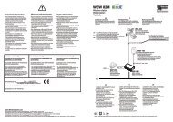
Electric cable routing for smoke and heat extraction systems<br />
Electrical cables always have<br />
to be laid in accordance with the national and local rules<br />
in your country.<br />
Do not use the green/yellow wire! -<br />
Cables of type NYM, concealed, can be used.<br />
For surface laying, halogen free safety cables are<br />
recommended (see cable plan).<br />
If possible, the use of cable types should be agreed with<br />
the Technical Services and the competent fire protection<br />
authority.<br />
For the maximum permissible cable lengths of the motor<br />
supply cables for the WSC 4XX system,<br />
taking the specified cable cross sections into account<br />
(cable information for surface laying),<br />
please refer to the “Cable lengths table" page 4.<br />
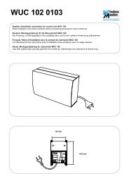
WSC 4XX<br />
G<br />
Panel<br />
WSC 4XX<br />
Supply cable<br />
230 V AC 50 Hz<br />
Fuse separately!<br />
SHE control panel WSC 4xx<br />
Ventilation button<br />
Winddetector<br />
Raindetector<br />
Automatic detectors ( if available )<br />
Maximum<br />
10 pieces<br />
Observe installation guidlines of VDE 0108!<br />
Wiring declaration only valid in case of surface laying.<br />
Junction box last or only actuator<br />
with terminal module<br />
Maximum<br />
10 pieces<br />
Maximum<br />
10 pieces<br />
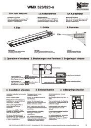
Recommendable Wiring laying:<br />
A = (N)HxH-FE180/E30<br />
B = JE-H(St)H E30/E90 2 x 2 x 0,8 mm<br />
C = JE-H(St)H E30/E90 4 x 2 x 0,8mm<br />
D = Silikon FRNC, 2 x 0,75 mm²<br />
E = J-Y(St)Y 2 x 2 x 0,8mm<br />
F = NYM-O, 5 x 1,5 mm²<br />
G = JE-H(St)H E30/E90 3 x 2 x 0,8 mm<br />
Cable plan for<br />
connections toWSC 4XX<br />
3
Electrical cables for smoke and heat extraction (SHE)<br />
systems<br />
All electrical cables must be routed in accordance with the individually valid VDE regulations.<br />
Cable function retention<br />
The current cable system directive (German LAR) is For function retention purposes, concealed routing<br />
decisive for the cable quality and the corresponding does not represent an approved type of routing as<br />
type of routing. suggested by DIN 4102, Part 12. Function retention is<br />
The sample cable system directive (German MLAR) also only ensured by cables of the E30 classification,<br />
issued in March 2000 was published in each German or if the room is monitored by smoke detectors.<br />
province as the cable system directive (German LAR).<br />
These province regulations, in their individually latest The cable network for SHE systems (“cable system”)<br />
versions, define the safety standards for electrical terminates at the interface (junction box) of the<br />
installations and represent, as such, the state of the actuator! The flexible, heat resistant connection cable<br />
art. of the SHE actuator is part of the system component<br />
Function retention of the E30 classification is sufficient 'electric motor controlled actuator' and is not part of<br />
for natural smoke extraction systems. These cables the electrical installation!<br />
have to be tested and must be approved in<br />
accordance with DIN 4102, Part 12. Cable routing has In all cases, we recommend to coordinate the type<br />
to be carried out according to the specifications of the of cable routing with the competent fire protection<br />
cable manufacturers using the corresponding authorities, even if the LARs are introduced as<br />
fastening materials. Function retention for SHE cables technical construction regulation in the provinces<br />
is not required if all cable paths are monitored by concerned.<br />
smoke detectors which, when tripped, cause the<br />
automatic detector to open the SHE system.<br />
Cable length table<br />
For the maximum permissible cable lengths or the SHE centre unit in conjunction with the standard actuators, taking into<br />
account the specified line cross sections, please refer to the following table:<br />
Maximum motor current per group module: 8 A (Note: Note the overall capacity/rating of the SHE centre unit!)<br />
Maximum cable length: (always routed from the central control panel to the last junction box)<br />
Actuating current: Sum of all motor currents per group module<br />
Note: Do not use the PE wire / green/yellow wire!<br />
Per motor supply line, 3 wires are required (2 wires current carrying /1 wire for monitoring)<br />
Cross section 3 wire 5 wire 3 wire 5 wire 3 wire 3 wire<br />
1.5 mm² 1.5 mm² 2.5 mm² 2.5 mm² 4 mm² 6 mm²<br />
Actuator current 2 wires in parallel 2 wires in parallel<br />
in amps<br />
1 84.00m 168.00m 140.00m 280.00m 224.00m 336.00m<br />
2 42,00m 84.00m 70,00m 140.00m 112.00m 168.00m<br />
3 28.00m 56.00m 46,67m 93,33m 74,67m 112.00m<br />
4 21,00m 42,00m 35,00m 70,00m 56.00m 84.00m<br />
5 16,80m 33,60m 28,00m 56.00m 44,80m 67,20m<br />
6 14,00m 28.00m 23,33m 46,67m 37,33m 56.00m<br />
7 12.00m 24.00m 20,00m 40.00m 32.00m 48.00m<br />
8 10,50m 21,00m 17,50m 35,00m 28.00m 42,00m<br />
(The information is valid for ambient temperatures of 25°C)<br />
Formula for the calculation of the maximum cable length<br />
Maximum permissible voltage drop in the cable UL: 2 Volt<br />
max. cable length = permissible voltage drop(UL) x conductivity of copper(56) x cable cross section(a)<br />
max. actuator current total (I) in amps x 2<br />
Permissible cable length for the SHE system button supply cable when using 4x2x0.8mm up to 200m<br />
The motor connection cable length to the junction box (or control module) must not exceed 10 m.<br />
SHE control panel WSC 4xx<br />
4
Cable plan WSC 4XX<br />
SHE control panel WSC 4xx<br />
²<br />
²<br />
Transmissin of the slave-signal to the next control panel<br />
3 x 2 x 0,8mm² max.. 200m<br />
5
Wiring diagram WSC 4XXwith Solo actuator<br />
SHE control panel WSC 4xx<br />
6
Wiring diagram WSC 4XX with Synchron module<br />
SHE control panel WSC 4xx<br />
7
Wiring diagram WSC 4XX with tandem control module<br />
SHE control panel WSC 4xx<br />
8
Wiring diagram WSC 4XX WMX / WMU<br />
SHE control panel WSC 4xx<br />
9
Wiring diagram WSC 4XX WLA<br />
Next panel<br />
Transmission of wind/rainsignal<br />
24V / DC / 0,5A<br />
SHE control panel WSC 4xx<br />
10
Wiring diagram WSC 416 Main wiring<br />
SHE control panel WSC 4xx<br />
11
Wiring diagram WSC 424 - 4XX Main wiring<br />
SHE control panel WSC 4xx<br />
12
Control panel WSC 416 / Compendium<br />
1<br />
2<br />
Main connecting board<br />
transformer fuse<br />
secondary Accu fuse<br />
Transformer<br />
1 Cable Conduit<br />
2 Transformer<br />
3 Power supply card WSA 471<br />
4 Main connecting board WSA 470<br />
5 main card WSC 4xx<br />
6 Module slots<br />
4<br />
Cable conduit<br />
Emergency - Open<br />
operate/trouble<br />
5<br />
3<br />
SHE control panel WSC 4xx<br />
LED red<br />
LED green<br />
6<br />
LED red<br />
LED green<br />
1 2<br />
LED red<br />
LED green<br />
Sw1 Sw1<br />
Sw2 Sw2<br />
2 x Accumulator<br />
6 6<br />
1 2<br />
CLOSE<br />
OPEN<br />
13
Control panel WSC 424 - WSC 4XX / Compendium<br />
1<br />
2<br />
Transformer<br />
1 Cable conduit<br />
2 Transformer<br />
3 Power suply card WSA 471<br />
LED red<br />
LED green<br />
5 Main connecting board WSC 4xx<br />
6 Module slots<br />
Emergency - Open<br />
operate/trouble<br />
Accumulator<br />
7 Control panel extension WSA 44X<br />
5<br />
3<br />
6<br />
Cable conduit<br />
LED red<br />
LED green<br />
LED red<br />
LED green<br />
1 Sw1 1 Sw1<br />
2<br />
2<br />
6 6<br />
Sw2 Sw2<br />
SHE control panel WSC 4xx<br />
CLOSE<br />
OPEN<br />
LED red<br />
LED green<br />
7<br />
1 Sw1<br />
2<br />
Sw2<br />
LED red<br />
LED green<br />
1 2<br />
Sw2<br />
Sw1<br />
LED red<br />
LED green<br />
1 Sw1<br />
2<br />
Sw2<br />
Accumulator<br />
LED red<br />
LED green<br />
LED red<br />
LED green<br />
1 Sw1 1 Sw1<br />
2<br />
2<br />
Sw2 Sw2<br />
6 6 6 6 6<br />
CLOSE<br />
OPEN<br />
14
Technical function discription /technical information<br />
Basic PCB WSC 4XX<br />
Sw1<br />
Sw2<br />
Switch1<br />
Switch 2<br />
Switch 1<br />
Switch 2<br />
Switch 3<br />
Switch 4<br />
Emergency - Open<br />
operate/trouble<br />
LED red<br />
LED green<br />
1 WSC 4XX Sw1 1 Sw1<br />
2<br />
2<br />
Function<br />
ventilation “CLOSE”<br />
ventilation “OPEN”<br />
emergency OPEN<br />
emergency CLOSE<br />
actuator fault<br />
Sw2 Sw2<br />
By delivery status the SHE group modules WSA 411 are placed beginning from the left<br />
in module place 1 futher to the right. Modules WSA 421 are placed directly behind<br />
the SHE-group modules. If the main configuration will be changed, the assignment of the<br />
SHE-groups and ventilation lines must be resetted by DIP-switch Sw1 und Sw2 on the main board.<br />
LED red<br />
LED green<br />
For a SHE-group with several ventilation lines the ventilation line groups WSA 421 must be<br />
ranged directly behind the SHE -group modules WSA 411 the connection of the functions<br />
will be realized by DIP-switch Sw1 and Sw2.<br />
** Attention: Assure that all 4 DIP-switches of the group Sw1and Sw2 be ON or OFF!<br />
Earth(mass) ventilation (from SHE-group module)<br />
SHE control panel WSC 4xx<br />
LED red<br />
LED green<br />
Switch-<br />
position ON<br />
ventilation ventilation<br />
shared seperat<br />
Switch<br />
position OFF<br />
SHE<br />
shared<br />
CLOSE<br />
OPEN<br />
SHE<br />
seperat<br />
15
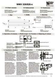
Master-slave coupling of 2 WSC 4XX-control panels<br />
With a master-slave coupling two smoke ventilation group modules in two different SHE-control panels can be coupled<br />
into only one SHE-group.<br />
The master control panel is extended with relay-modules built in the production.<br />
The master control panel is a “WSC 4XX XX XXC 0101”.<br />
The “C” at 8’th place indicates it is a master control panel.<br />
When two SHE-control panels are coupled in a master-slave connection, it is possible to operate all the motors with<br />
signals from the sensors coupled to the master control panel and to operate single motors with the signals from the<br />
sensors coupled to the slave control panel.<br />
On the break glass unit, which is coupled to the smoke ventillation group module in the master control unit, it is<br />
possible to activate the emergency-open and -close of the motors coupled to the slave control unit.<br />
If a fault occurs in the slave coupling, a FAULTsignal will be sent from the slave-central to the master-central and the<br />
FAULTsignal is shown in the master-slave “Break glass unit”<br />
If more than 2 master-slave panels are to be coupled, all the control panels except the last one are to be built as<br />
master control panels.<br />
Break glass unit WSK 320 / WSK 330<br />
Smoke detector WSA 300 / WSA 310<br />
ABA-signals<br />
1 2 3 4 5 6<br />
Cable length max.200m<br />
(JE-H(St)H E90 3 x 2 x 0,8 mm)<br />
MASTER - CENTRAL - SLAVE<br />
......................<br />
X3-Xn<br />
WSA<br />
411<br />
Master Slave<br />
9 8<br />
Smoke ventilation group module WSA 411<br />
SHE control panel WSC 4xx<br />
X1<br />
8 12<br />
8 7<br />
X3-Xn<br />
FAULT<br />
EMERGENCY OPEN<br />
EMERGENCY CLOSE<br />
16
Technical function discription /technical information<br />
Power pack module WSA 471<br />
Setting and display elements<br />
The power pack module is equipped with the following operating and display elements<br />
Display:<br />
Display:<br />
Display:<br />
Display:<br />
Setting:<br />
Setting:<br />
Reset:<br />
Setting:<br />
For the setting of the detector voltage and checking and setting the accumulator mode and<br />
the loading voltage for smoke and heat extraction systems, please refer to the following pages.<br />
Malfunction message and its remedy<br />
Malfunction:<br />
Remedy:<br />
Malfunction:<br />
Remedy:<br />
X2<br />
F1 F2 F3 F4 F5<br />
Mains/accumulator<br />
malfunction<br />
Group multi-input<br />
malfunction warning<br />
Operation<br />
Mains<br />
Load voltage<br />
DIP switch<br />
Buzzer<br />
Display: EMERG.<br />
OPEN<br />
Reset<br />
Detector voltage<br />
Off On<br />
PTC<br />
The yellow control LED flashes immediately when a<br />
mains failure occurs, or after 5 minutes in the event<br />
of an accumulator fault, is lit in the event of an accumulator failure.<br />
The yellow control LED is lit in the event of a group malfunction or<br />
motor cable fault (multi-input malfunction warning for all SHE and<br />
ventilation modules), however, not in the EMERGENCY mode<br />
(accumulator).<br />
The green control LED is lit under the following conditions:<br />
-no power failure, no accumulator fault<br />
-no group malfunction (manual/automatic detectors)<br />
-no motor malfunction<br />
The green control LED is lit under the following conditions<br />
Mains voltage applied.<br />
Setting the operating and loading voltage<br />
Not assigned.<br />
Alarm siren with "EMERG. OPEN" - Off/On<br />
Malfunction: only malfunction buzzer -Off<br />
or malfunct.buzzer and alarm siren -On<br />
( Malf.buzzer not active in the event of a mains failure)<br />
Internal malfunction buzzer OFF or ON.<br />
Red control LED is lit when a SHE<br />
group was tripped<br />
(Multi-input alarm for all SHE modules)<br />
Siren reset button.<br />
Automatic reset after 4 min.<br />
Setting of the detector voltage<br />
The yellow control LED "Mains/accumulator" malfunction flashes immediately if no<br />
mains voltage is applied to the basic PCB of the WSC 4XX, or after 5 min,<br />
when the set loading voltage is lower than 26V.<br />
The LED has steady light in the event of an accumulator malfunction.<br />
- Ensure that mains voltage is applied to the connection elements of the basic PCB.<br />
- Ensure that the set loading voltage exists and is correctly set.<br />
- Ensure that the accumulators including the bridging cables are connected.<br />
The yellow control LED "Group multi-input malfunction warning" is lit when one of the<br />
detectors or actuators connected to WSC 4XX has a fault<br />
(this malfunction message is not available when the system is in its accumulator mode).<br />
- Ensure that the corresponding detector voltage is applied to the measuring point (see setting<br />
of the detector/loading voltage).<br />
- Check the end modules (detectors/actuators) and jumpers (SHE operating point).<br />
- Cable check of all detectors and actuators.<br />
SHE control panel WSC 4xx<br />
17
Technical function discription /technical information<br />
SHE-group module WSA 411<br />
Setting and display elements<br />
The SHE group module WSA 411 is equipped with the following operating and display elements.<br />
Fuse<br />
Display<br />
Display<br />
DIP switch<br />
setting<br />
Fuse<br />
Display<br />
Reset<br />
0.2 AM<br />
display<br />
X....<br />
EMERGENCY -<br />
OPEN Manual detector<br />
Malfcunction<br />
EMERGENCY -<br />
OPEN Autom. Detector<br />
Malfunction<br />
8AT<br />
Motor<br />
Malfunction<br />
Motor<br />
Reset<br />
OFF<br />
Motor<br />
Manual detector<br />
Autom. Detector<br />
Ventilation<br />
Malfunction message and its remedy<br />
Malfunction:<br />
Remedy:<br />
Malfunction:<br />
Remedy:<br />
Malfunction:<br />
Remedy:<br />
ON<br />
Fuse of the external display "OPEN-CLOSED".<br />
The red control LED is lit during the "EMERGENCY OPEN"<br />
function of the manual detector group.<br />
The yellow control LED is lit during the "EMERGENCY OPEN"<br />
function of the manual detector group.<br />
The red control LED is lit during:<br />
- "EMERG.OPEN" function of the autom. detector group.<br />
- the malfunction of a motor group,<br />
if DIP switches 4 are on "ON".<br />
The yellow control LED is lit during a malfunction<br />
of the automatic detector group.<br />
Display only in the event of a malfunction of the motor group -Off<br />
or display and "EMERG.OPEN" in the event of a<br />
malfunction of the motor group.<br />
-On<br />
Display only in the event of a malfunction of the manual<br />
detector group<br />
-Off<br />
or display and "EMERG.OPEN" in the event of a malfunction<br />
of the manual detector group<br />
Display only in the event of a malfunction of the automatic<br />
detector group<br />
or display and "EMERG.OPEN" in the event of a malfunction<br />
of the automatic detector group.<br />
Home position<br />
Motor fuse<br />
Yellow control LED is lit in the event of<br />
malfunction of the motor group<br />
Reset of the smoke and manual detectors<br />
(EMERGENCY OPEN) Motors "CLOSE".<br />
The yellow control LED "Manual detector malfunction" is lit when the manual detector<br />
group monitored by the rest current is interrupted/disturbed.<br />
- Ensure that the corresponding detector voltage is applied to the measuring point (see setting of<br />
the load voltage).<br />
- Check the connection of the termination resistor (10K Ohm).<br />
- Check the cables of all buttons/keys.<br />
The yellow control LED "Automatic detector malfunction" is lit when the detector group<br />
monitored by the rest current is interrupted/disturbed.<br />
- Ensure that the corresponding group voltage is applied to the measuring point (see setting of<br />
the load voltage).<br />
- Check the connection of the termination resistor (10K Ohm).<br />
- Check the cables of automatic detectors.<br />
The yellow control LED "Motor malfunction" is lit when one of the connected motors has<br />
a malfunction.<br />
- Check the motor fuse.<br />
- Check the connections of the motor end module in the last or only drive.<br />
- Check the cables of all drives.<br />
SHE control panel WSC 4xx<br />
-On<br />
-Off<br />
-On<br />
-On<br />
18
Technical function discription /technical information<br />
Ventilation line module WSA 421<br />
Setting and display elements<br />
The ventilation control module WSA 421 includes the following operating and display elements:<br />
Fuse<br />
Setting<br />
Fuse<br />
Display<br />
X....<br />
0.2 AM<br />
Home pos.<br />
8AT<br />
Motor<br />
Malfunction<br />
Motor<br />
Malfunction message and its remedy<br />
Malfunction:<br />
Remedy:<br />
Fuse of the “OPEN-CLOSE” display<br />
Motor fuse<br />
The yellow control LED is lit in the<br />
event of a cable interruption/disturbance<br />
of the motor line.<br />
The yellow control LED "Motor malfunction" is lit when one of the connected<br />
motors has a malfunction.<br />
- Check the motor fuse.<br />
- Check the connections of the motor end module in the last or only motor.<br />
- Check the cables of all motors.<br />
SHE control panel WSC 4xx<br />
19
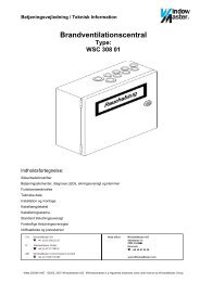
Technical function discription /technical information<br />
Gap-ventilation line module WSA 404<br />
Function<br />
It is not always necessary for an electric actuator to open a ventilation<br />
unit (window or light dome) by ist full stroke<br />
Sometimes a small gap is sufficient for ventilation purposes.<br />
This module enables time-controlled limitation of the actuator stroke.<br />
The module does not affect the actuator when an “EMERGENCY OPEN”<br />
function is triggered, in this case, the actuator opens by the maximum<br />
stroke.<br />
The gap ventilation module can be connected to all SHE systems.<br />
The module has to be installed between the SHE panel and the<br />
ventilation switch, timer or temperature sensor.<br />
The power supply will be provided by the control panel or<br />
an external power supply unit.<br />
The opening time can be set in a range of<br />
1 - 60 sec. / 2 - 120 sec.<br />
(with activated Jumper J1).<br />
The status “OPEN” will be visualized by a steady red LED,<br />
the status “CLOSE” will be visualized by a steady green LED.<br />
Flash light during operation.<br />
Technical data:<br />
Supply voltage: 18 – 36VDC<br />
Current consumption: approx. 10mA<br />
OPEN-CLOSE contacts: zero potential contacts<br />
max 1A at 30V<br />
Input:<br />
Operating input: TTL-Level, low active<br />
CLOSE signal input: 12 – 36 VDC, zero potential (unpoled)<br />
Time range: 1 – 60 sec / 2 – 120 sec.<br />
(activated Jumper J1)<br />
Casing (WxHxD): 49 x 50 x 96mm<br />
(for installation channel T35)<br />
open<br />
KL 2<br />
KL 2<br />
1 2 3 4 1 2 3 4<br />
close<br />
L<br />
red<br />
only with isa-button<br />
IC-LT 204<br />
display-open<br />
open close<br />
Ventilation push button or Temperature sensor<br />
Timer<br />
SHE control panel WSC 4xx<br />
X 2<br />
SHE-Panel WSC 4XX<br />
The Ventilation function must be in<br />
self-hold-modus<br />
KL 1<br />
close<br />
open<br />
X 3<br />
60/120 sec. 1/2 sec.<br />
red green<br />
open close<br />
J1<br />
com<br />
close-sig.<br />
close-sig.<br />
15/30 sec.<br />
KL 2<br />
1 2 3 4<br />
(Connection as shown on the left)<br />
Time range adjusting<br />
1-60sec. / 2-120sec.<br />
Connection schematic<br />
gap-ventilation-module<br />
WSA 4XX<br />
20
Technical function discription /technical information<br />
Connection of the external fire alarm system WSA 306<br />
X....<br />
actuator connection<br />
Ventilation switch<br />
Connection<br />
SHE<br />
Connection<br />
X....<br />
1,5K 10K<br />
FAS-module<br />
WSA 306<br />
General information<br />
The smoke detector input can be used for transmitting on a signal from an external fire detecting system (FAS) .<br />
This requires a potential-free FAS contact and the FAS module (green).<br />
FAS OPEN function<br />
To generate a trip (EMERGENCY OPEN) of the SHE group actuate the potential-free contact in the FAS. All<br />
SHE actuators “OPEN” automatically. The ventilation buttons are now out of operation.<br />
Resetting the FAS OPEN function<br />
Once the FAS central unit has been reset (tripping contact open again), actuate the CLOSED button on the main<br />
operating panel of the SHE system or the Reset button in the central unit<br />
The SHE actuators "CLOSE" and the ventilation buttons are operational again.<br />
Malfunction message and its remedy<br />
Malfunction:<br />
FAS central unit pot.-free tripping contact (N/O)<br />
Malfunction: The yellow control LED “Malfunction (automatic detector)” is lit when the group FAS<br />
connection, monitored by a closed-circuit current, is interrupted / faulty.<br />
Remedy: - Ensure that the detector voltage is applied to the measuring point (see Setting the load<br />
voltage).<br />
- Check the connection of the terminal resistor (FAS module).<br />
- Check the cables to the FAS.<br />
SHE control panel WSC 4xx<br />
21
Technical function discription /technical information<br />
Setting the detector and accumulator voltage<br />
The detector voltage must be 21V DC (±5%).<br />
This is directly controlled by the controller on the power pack module. The measurement is made at X......<br />
terminal 7/8 of a SHE group module WSA 411<br />
Switching on the voltage measuring<br />
instrument to establish the detector<br />
voltage<br />
X2 X....<br />
F1 F2 F3 F4 F5<br />
Load voltage<br />
Power pack PCB<br />
Detector voltage<br />
V<br />
Setting the accumulator operating<br />
and load voltage (see following table)<br />
Setting the detector voltage 21V DC<br />
The accumulator load voltage depends on the capacity of the accumulators installed.<br />
For the required values please refer to the following point. Only correct the regulation in the event of discrepancies.<br />
Checking and setting the accumulator operating and load voltage<br />
Only allow trained and authorised personnel to carry out maintenance work on smoke and heat extraction systems.<br />
The accumulators used do not require maintenance throughout their operating life. For maintenance,<br />
check the load and accumulator voltages at regular intervals<br />
With the accumulator connected, the accumulator voltage must be between 27.6 Volt and 27.7 Volt.<br />
Attention: The accumulator load voltage is set to UTU<br />
= 25°C. Correct the setting should the temperature deviate.<br />
The load voltage depends on the type of accumulator used and can be taken from the following table:<br />
Setting the load voltage:<br />
Control panel Capacity 1,2Ah - 6Ah<br />
10Ah - 65Ah<br />
WSC 4XX Load voltage 27,7V 27,8V<br />
3<br />
- Provide a digital multimeter with at least a 3 / 4 digit display<br />
-<br />
Disconnect the accumulator and connect the multimeter to the<br />
accumulator cables.<br />
Set the load voltage according to the above table, knowing that accumulators start gassing once the load voltage<br />
is exceeded, which reduces the accumulator capacity. An insufficient load voltage prevents a full<br />
charge which means that in an emergency the energy available will not be sufficient.<br />
SHE control panel WSC 4xx<br />
+<br />
Accumulator<br />
Cables from the<br />
Control panel<br />
-<br />
Multimeter<br />
U<br />
22
Start up WSC 4XX<br />
General information<br />
The and heat extraction system (SHE) panel unit WSC 4XX is not equipped with a main switch. For this reason, we<br />
recommend to circuit the supply voltage (230V/400V AC) via an external or on site pre-fuse.<br />
(230V = 1 pole / 400V = 3 pole )<br />
Please check the following:<br />
· the settings of the slide switches on the main PCB<br />
· the settings of the detector voltage as well as the accumulator operating and charging voltage,<br />
· the accumulator charge status. To secure the emergency power supply, charge the accumulators for<br />
approx. 8 hours when installed, prior to them being operated.<br />
· actuator voltage in open circuit. If the value exceeds 32V the primary input on the transformator must be<br />
moved from 230V to 241V or +20V.<br />
The SHE system is operational once the final configuration is reached after the installation of required and, if<br />
necessary, corresponding plug-in assembly groups, and following the setting of all desired functions and the above<br />
checks.<br />
Operation<br />
The system is factory-programmed in accordance with the customer's requirements. Operation of the system by the<br />
user/owner's instructed personnel is then restricted to the following operating modes:<br />
· Opening the smoke extractions in the event of a fire:<br />
By actuating the „OPEN“ button in the SHE system button or by pressing the DIN button as well as by automatic<br />
detectors and when a signal arrives from external fire detecting systems.<br />
· Closing the smoke extractions following an „EMERGENCY OPEN":<br />
By actuating the „CLOSED“ button in the SHE system button or by pressing the „Reset“ button on the SHE group<br />
module WSA 411(IT-M22/101) and subsequently pressing the ventilation button „CLOSED“.<br />
· Ventilation function:<br />
OPEN/CLOSED The motorised actuators of the smoke extractions run in the corresponding<br />
directions after actuating the direction key ( or ) in the ventilation button.<br />
Operating control<br />
STOP The actuators stop at their current position after pressing both direction keys at<br />
the ventilation button simultaneously.<br />
(Only possible with LT buttons with stop function! )<br />
Please refer to the signal LED's at the front panels of the individual modules or various connected signal units for the operating<br />
control and the message about the operating status of the entire system.<br />
SHE control panel WSC 4xx<br />
23
Review of fuses WSC 4XX<br />
Review of fuses WSC 416, 16A<br />
Fuses on the main connection PCB<br />
F1 Power fuse T 2,0A<br />
F2 Secondary fuse, mains transformer 20A FKS<br />
F3 Accumulator main and charge fuse 20A FKS<br />
Pre-fuse in the distribution 4A autom.cut out with characteristic type C<br />
Fuses on the main PCB<br />
F1 Fuse, emergency open display - external F 0,2A<br />
F2 Fuse, siren F 0,2A<br />
F3 Fuse, mains display F 0,2A<br />
F4 Fuse, operating display PTC<br />
F5 Fuse, multi-input malfunction F 0,5A<br />
Fuse of the displays on the SHE module M 0,2A<br />
Fuse of the motors on the SHE module T 8A<br />
Fuse of the displays on the ventilation module M 0,2A<br />
Fuse of the motors on the ventilation module T 8A<br />
Review of fuses WSC 4XX, 24 to 64 A<br />
F1 Fuse, emergency open display - external F 0,2A<br />
F2 Fuse, siren F 0,2A<br />
F3 Fuse, mains display F 0,2A<br />
F4 Fuse, operating display PTC<br />
F5 Fuse, multi-input malfunction F 0,5A<br />
F6 Power fuse For the value, please refer to the table below<br />
F7 Accumulator main and charge fuse For the value, please refer to the table below<br />
F8 Secondary fuse, mains transformer For the value, please refer to the table below<br />
Centre unit<br />
Rated<br />
current<br />
Rated<br />
capacity<br />
F6 F7 F8<br />
Pre-fuse in the<br />
distribution<br />
WSC 416 16A 400VA T 2,0 20A FKS Neozed 20A FKS Neozed 4A autom. cut out<br />
WSC 424 24A 630VA T3,15A 25A FKS Neozed 25A FKS Neozed 4A autom. cut out<br />
WSC 432 32A 800VA T 4,0A 35A FKS Neozed 35A FKS Neozed 6 A autom. cut out<br />
WSC 448 48A 1600VA T 8,0A 50A FKS Neozed 50A FKS Neozed 10A<br />
autom. cut out<br />
WSC 464 64A 1600VA T 8,0A 63A FKS Neozed 63A FKS Neozed 10A<br />
autom. cut out<br />
SHE control panel WSC 4xx<br />
with characteristic<br />
Type C<br />
24
Maintenance and repair WSC 4XX<br />
We recommend to carry out maintenance and a function check of the entire smoke and heat extraction (SHE) system at regular<br />
intervals. Perform the maintenance in accordance with DIN 18232, the VdS regulations, the sample construction regulations and<br />
the manufacturer guidelines at intervals of one year; we recommend to carry out the function check at one month intervals.<br />
Only allow specially trained personnel to carry out the checks.<br />
To be able to carry out the maintenance and repair work on the SHE system, isolate the system from the supply voltage (230 V AC)<br />
by actuating an external or customer-supplied, two-pole or all-pole cut-out switch.<br />
Work to be performed at the SHE control panel<br />
· Check the mains voltage (230 V AC ),<br />
· check the firm seating of all terminal connections,<br />
· check cables and connection wires for damage,<br />
· check the displays and keys on the modules,<br />
· check all fuses in the centre unit,<br />
· check the line voltage,<br />
· check the accumulator voltage (should there be a deviation from the existing mains voltage, correct the voltage value<br />
by regulation),<br />
· check the installation date of the accumulator and, if necessary, replace (replacement becomes due four years after<br />
the accumulator installation date),<br />
· dispose of used accumulators in accordance with the regulations,<br />
· note the replacement date on the accumulator.<br />
Replacement of modules<br />
Depending on its equipment version, the system includes a certain number of modules which have to be either removed to change the<br />
system and/or to be additionally installed or to be replaced during repair.<br />
During repair with the system configuration unchanged:<br />
· isolate the system or disconnect it from the mains and the accumulators,<br />
· pull out the plug-in group, insert replacement assembly group.<br />
If the system configuration has to be changed or extended:<br />
· isolate the system or disconnect it from the mains and the accumulators,<br />
· pull out the plug-in assembly group and/or insert the new assembly group,<br />
· set the miniature slide valves on the main PCB in accordance with the <strong>instruction</strong>s.<br />
On the actuators<br />
· check the actuators for perfect function and condition,<br />
· check the motor end module for correct connection,<br />
· check flaps, windows, domes etc. for smooth operation,<br />
· check the direction of movement of the actuators when the „OPEN“ or „CLOSED“ button is actuated,<br />
· clean actuators when soiled,<br />
· check consoles and fasteners for firm seating and condition.<br />
At the detectors<br />
· check the function of all DIN buttons and ventilation buttons. (Do the actuators move in the direction shown on<br />
the buttons?)<br />
· check the displays in the keys,<br />
· replace defective glass covers or damaged components,<br />
· check the function of smoke detectors with test gas and thermal maximum detectors using a hot air hair dryer.<br />
· Does the red LED light up once the smoke detectors have tripped?<br />
· Remove soiled or defective smoke detectors and return same to the manufacturer for repair or cleaning.<br />
SHE control panel WSC 4xx<br />
25