CODE Tutorial 1 - W. Theiss Hard- and Software
CODE Tutorial 1 - W. Theiss Hard- and Software
CODE Tutorial 1 - W. Theiss Hard- and Software

Create successful ePaper yourself
Turn your PDF publications into a flip-book with our unique Google optimized e-Paper software.
<strong>CODE</strong> <strong>Tutorial</strong> 1 Example 1: Low-E coatings<br />
2 Example 1: Low-E coatings<br />
2.1 The problem: Infrared emission of glass<br />
This example shows how a three layer coating on glass is designed for a certain application. The<br />
application of the layer system under discussion is to reduce the infrared emission of architectural<br />
glass used in office buildings or private houses. In addition to this purpose you can use the<br />
coating also for achieving a certain appearance, i.e. a certain color of the pane.<br />
In a first step we identify the problem of infrared emission by inspecting the performance of<br />
uncoated glass.<br />
Start <strong>CODE</strong> <strong>and</strong> activate File|New to start with an empty configuration. Then press F7 to enter<br />
the treeview level. For our considerations we need optical constants of glass from the infrared to<br />
the near UV. The data that come with this tutorial contain a fixed data set that you can use.<br />
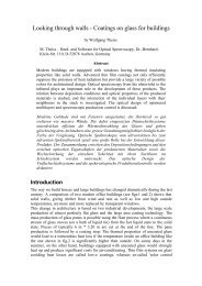
Create in the list of materials a new object of type 'Imported dielectric function'. Open it <strong>and</strong><br />
load with the local comm<strong>and</strong> File|Open the file glass.df. Press the 'a' key to autoscale the<br />
graphics <strong>and</strong> you should find this:<br />
Dielectric function<br />
8<br />
7<br />
6<br />
5<br />
4<br />
3<br />
2<br />
1<br />
-0<br />
Glas T4S total<br />
10000 20000 30000 40000 50000<br />
Wavenumber [cm -1 ]<br />
To compute the emission of a glass pane with these optical constants define a layer of type<br />
'Thick layer' with a thickness of 4 mm between two vacuum halfspaces.<br />
Glass is a material with a quite large infrared absorption. In the spectrum list, define two<br />
spectrum simulation objects <strong>and</strong> use them to compute the infrared reflectance <strong>and</strong> transmittance<br />
spectrum (50 ... 5000 1/cm, 500 data points) of the pane (assume normal incidence of light).<br />
Call them 'R IR' <strong>and</strong> 'T IR'. When you are ready use the main menu comm<strong>and</strong> Actions|Create<br />
view of spectra to generate a simple view showing the 2 spectra. The configuration<br />
tu1_ex1_step0.wcd contains the configuration that you should have by now:<br />
5<br />
© 2012 Wolfgang <strong>Theiss</strong>