tesi R. Miscioscia.pdf - EleA@UniSA
tesi R. Miscioscia.pdf - EleA@UniSA
tesi R. Miscioscia.pdf - EleA@UniSA

You also want an ePaper? Increase the reach of your titles
YUMPU automatically turns print PDFs into web optimized ePapers that Google loves.
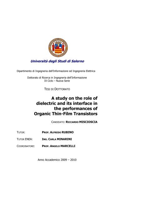
Università degli Studi di Salerno<br />
Dipartimento di Ingegneria dell’Informazione ed Ingegneria Elettrica<br />
Dottorato di Ricerca in Ingegneria dell’Informazione<br />
IX Ciclo – Nuova Serie<br />
TESI DI DOTTORATO<br />
A study on the role of<br />
dielectric and its interface in<br />
the performances of<br />
Organic Thin-Film Transistors<br />
TUTOR: PROF. ALFREDO RUBINO<br />
TUTOR ENEA: ING. CARLA MINARINI<br />
CANDIDATO: RICCARDO MISCIOSCIA<br />
COORDINATORE: PROF. ANGELO MARCELLI<br />
Anno Accademico 2009 – 2010
“So once you know what the question actually is, you'll know<br />
what the answer means.”<br />
Douglas Adams (The Hitchhiker's Guide to the Galaxy)
Acknowledgments<br />
It is a pleasure to thank those who made this thesis possible. It’s a<br />
really long list.<br />
I am grateful to my ENEA supervisor, Dr. Eng. Carla Minarini<br />
who has supported me with her hints and reflections, encouragement<br />
and a great working environment.<br />
This thesis would not have been possible unless my advisor, prof.<br />
Alfredo Rubino, for the support and the time he spent to give a great<br />
input to my work.<br />
A special thank goes to my Ph.D. School coordinator, Professor<br />
Angelo Marcelli who has been always a source of inspiration and a<br />
good example to me. I am heartily thankful to Dr. Dario della Sala<br />
from ENEA who believed in my capabilities giving me the chance to<br />
work in the Organic Electronics field.<br />
My sincerest thanks go to Dr. Mario Petrosino from the University<br />
of Salerno, for the long time he spent sharing with me his knowledge<br />
talking about OTFTs, device processing, and other things.<br />
I owe my deepest gratitude to my friend and colleague, Dr.<br />
Giuseppe Nenna, for his friendship, loyalty, never-ending patience<br />
and inspiring talks on theoretical and experimental concepts of OE.<br />
I am indebted to my colleagues from ENEA who supported me for<br />
a long time. Dr. Anna de Girolamo del Mauro who has been great in<br />
material processing and characterization; for her availability and<br />
friendship. Dr. Paolo Tassini, for his guidance, for sharing with me his<br />
radical vision in fact of devices. To Dr. Paolo Vacca who has thought<br />
to me the basis of device’ and material processing and made possible<br />
the realization of my first OTFTs. To Dr. Romina Rega, for the patient<br />
help and the time she put in helping me. To Dr. Eugenia Bobeico who<br />
saved me in more than one difficult experimental moments, for her<br />
friendship and patience.<br />
I would like to show my gratitude to Mr. Valerio Cerri and<br />
Tommaso Marcianò who shared with me the long hours in clean room<br />
making together every kind of deposition, patterning and etching<br />
processes. To Tommaso Fasolino and Antonio Romano for their help
II Acknowledgments<br />
in the measurement process, for the patience and good advices. To<br />
Antonio Citarella for all the ways he has been able to help me in any<br />
kind of processing difficulties, to Enzo Calò, Dr. Giuseppe Nobile, Dr.<br />
Fulvia Villani, Dr. Valentina Bizzarro, Dr. Eng. Saverio De Vito, Dr.<br />
Eng. Domenico Palumbo, Dr. Angelica Grimaldi, Dr. Eng. Antonio<br />
Imparato, Dr. Maria Grazia Maglione, Dr. Eng. Giuseppe Alonge, Dr.<br />
Tiziana Di Luccio, Dr. Vera La Ferrara, Dr Franco Roca and Dr.<br />
Ettore Massera and all ENEA People. Without their help and<br />
friendship I would not be able to make this work.<br />
A great thanks I have to dedicate to Dr. Loredana Freda who<br />
always saved me from my bad memory and shared the efforts of the<br />
academic study.<br />
In these long years of work, day to day, I had the chance to learn<br />
many complicated things. But the most valuable lesson I’ve been<br />
taught is really simple and I think it will be the only thing I will<br />
remember when all the rest will be gone and forgot: when you<br />
sacrifice to obtain a result there’s always someone that is silently<br />
paying for You a great part of the price of your effort. These ones are<br />
the people that really love You. Unconditionally. My purpose is not to<br />
avoid the challenges but to be happy and become the living proof<br />
they succeeded.<br />
For all these reasons the greatest thanks goes to my Parents, for<br />
their love and the patience they had with me. I thank Them because<br />
they have always been by my side and made me never feel alone<br />
walking this long way.<br />
Furthermore, I am grateful to my Parents in law also for the<br />
support they have given during this first times of my stay at the new<br />
home making easier to me to concentrate my efforts on the<br />
proofreading of this manuscript.<br />
Finally, I have to thank the One I madly love: my wife Maria.<br />
Because of her I did not surrender to difficulties and failures. The<br />
Love she has inside is the greatest gift I had from the life and the<br />
reason why I will try to be as good as my Parents have been with me.<br />
I will never be able to thank her enough.<br />
Thank You.
In loving memory of my uncle,<br />
Professor Pasquale Caruso
Contents<br />
Introduction 1<br />
Chapter 1: “Working Principles” 9<br />
Chapter 2: “A survey on the state<br />
of the art Organic Thin-Film<br />
Transistors processing” 29<br />
Chapter 3: “Gate-leakages in polymeric dielectrics<br />
and layout optimization” 85<br />
Chapter 4: “Morphology-mobility relationship in<br />
dielectrics with optimized surface-energy<br />
and its exceptions studied by means of<br />
density of states” 107<br />
Conclusions 145<br />
Appendix I: “Table of acronyms and symbols” 149
Introduction<br />
Nowadays, it has become accepted that the word "electronic"<br />
qualifies an object for performance and superior skills and even<br />
introduces a degree of "intelligence" (we usually speak about such<br />
smart-phones, intelligent washing machines etc.), meaning that the<br />
machine has a certain logic that allows it to make some (often not)<br />
simple decisions. The introduction of electronics in everyday life has<br />
led to the birth of what today is called information society, where<br />
information exchange and processing (voice, images, textbooks,<br />
geographic data etc…) has to be very fast and in even more growing<br />
amounts but, more important, as technology advances, common<br />
objects designed for different purposes are fabricated in order to<br />
embed some information processing and storage capability.<br />
For these reasons, if a well-established part of electronics<br />
concentrated its efforts on miniaturization, computational capabilities<br />
and volumes etc., a second part considers as its main purpose not the<br />
absolute performance in computing but the possibility to fabricate<br />
simple or complex devices or systems which are impossible to<br />
fabricate by means of standard silicon technology.<br />
Emissive, thin, transparent, optically active, flexible, light<br />
emitting, light sensing, energy harvesting devices, low-cost circuitry,<br />
displays and antennas are just some examples and applications of<br />
Organic Electronics (OE), a branch of the science and technology<br />
addressing the electronic devices made from carbon-based materials<br />
and their integration.<br />
Since the first evidences of the potential of organic materials in<br />
electronics when employed as conductors [1] or semiconductors [2] a<br />
multiplicity of desirable features made them appealing from industrial<br />
point of view as much to become a research priority of many<br />
industries, universities and research institutes worldwide.
2 Introduction<br />
The ability of today’s chemistry to synthesize organic molecules<br />
(Molecular Engineering) tailored for specific purposes and with<br />
features not common in inorganic semiconductors as silicon etc. has<br />
spread the objectives in the current landscape of applied scientific<br />
research and product development from the material development to<br />
device integration and then to device engineering, circuitry integration<br />
and optimization.<br />
This run has, time after time, required the profusion of ever greater<br />
efforts on the implementation and optimization of electronic devices<br />
which can be integrated into circuitry fabricated on large area, flexible<br />
substrates with low-cost manufacturing processes reduced complexity<br />
and high yield and productivity.<br />
As a result, a variety of fundamental electronic devices has been<br />
developed on the basis of organic materials (see figure 1).<br />
figure 1: organic electronics applications in basic devices.<br />
Organic Light-Emitting Diodes [3] are just one of the most cited<br />
and exploited of organic semiconductors applications to electronic<br />
devices in because of the advances in opto-electronics and display<br />
technology. Furthermore, there is a plethora of studies which report<br />
Organic Semiconductors (OSCs) to be effective as building blocks of<br />
sensors, lasers, photodetectors, solar cells, rechargeable batteries,<br />
organic thin film transistors, RFIDs, wireless power transmission<br />
equipments etc.
Introduction 3<br />
The drawbacks of organic technology are often related to low<br />
charge-mobility and poor electrical performances. In part this is due<br />
to chemical, electrical and environmental stability issues and to the<br />
fact that process technology is still developing its instruments,<br />
methods and materials. For these reasons the cheaper processing<br />
technology of OE has still not reached the productivity and yield<br />
standards of the silicon technology.<br />
In order to meet the technological challenges of OE that in the<br />
always-demanding landscape of organic active matrix display<br />
(AMOLED)[3][4], the devices involved in the driving logic of pixels<br />
are particularly critical when coupled to organic emissive elements<br />
(OLED stacks) because from their performances depend refresh rates,<br />
image brightness and screen pixel densities. On a scale of<br />
deeper detail, the creation of screens for large area electroluminescent<br />
displays cannot be separated from the design and optimization of a<br />
backplane that for each pixel is able to drive the optically active<br />
element at constant current, and to persist the information’s state<br />
between a refresh and the other image.<br />
The primary building block of digital or driving logic in organic<br />
electronics is the Organic Thin-Film Transistor (OTFT). In this kind<br />
of device, like in conventional FETs, the voltage applied to an<br />
insulated terminal controls the concentration of mobile charge in a<br />
resistive conduction channel (see figure 2). Thus, the current flowing<br />
between the two electrodes (Source and Drain) at the edge of the<br />
channel is modulated by means of the variation of the charge induced<br />
by the gate potential being the current density j bound to the charge<br />
density n in an n-type semiconductor neglecting the p-type carriers<br />
and to electric field “E”[5]:<br />
eq. 1<br />
J DS n<br />
= qμ<br />
nE<br />
Drain current can then be varied between two extreme conditions:<br />
from an off-state (no-current) and a saturation state (on status).
4 Introduction<br />
figure 2: basic scheme of an OTFT. S=Source electrode, D=Drain electrode, tch = channel<br />
semiconductor thickness, tox=gate insulator thickness, L=channel length.<br />
For the reasons that have been already mentioned, the role of this<br />
kind of switching device is crucial in information displays field, thus<br />
major technology investments must be made to optimize the<br />
characteristics related to switching the power status of the pixel in<br />
order to obtain sufficient dynamics for a proper representation of<br />
moving pictures, movies, or whatever as required by the specifications<br />
set by applications where the display is intended.<br />
Some examples of applications of OTFTs can be seen in literature<br />
results cited in figure 3
Introduction 5<br />
Artificial Skin<br />
(OTFT+Pressure Sens.)<br />
http://ieeexplore.ieee.org/stamp/stamp.j<br />
sp?tp=&arnumber=1269242<br />
Microfluidics / Lab<br />
on chip<br />
http://rogers.mse.uiuc.edu/files%5<br />
C2003%5CAPL_83_2067.<strong>pdf</strong><br />
Braille display<br />
(OTFT+Actuators)<br />
http://ieeexplore.ieee.org/stamp/stamp.<br />
jsp?tp=&arnumber=1269242<br />
Sheet-type image scanners<br />
(OTFT+OPD)<br />
T. Someya et al., IEEE T-ED 52, 2502 (2005).<br />
Textile<br />
Electronics<br />
http://ieeexplore.ieee.org/st<br />
amp/stamp.jsp?arnumber=0<br />
1386597<br />
Insight into materials and<br />
surface properties:<br />
SC mobility, DOS, (intrinsic) Doping and<br />
carrier type, Photoconductivity G&R,<br />
Charge trapping,<br />
Energy levels and so on…<br />
RFID Tags<br />
Army, PolyIC, electro-com,<br />
OrganicID, E-ink Corp.<br />
Artificial retina (DOE)<br />
(OTFT+OPD)<br />
http://jjap.ipap.jp/link?JJAP/45/4419/<br />
Wireless power transmission<br />
sheet<br />
(OTFT + Inductive coupling)<br />
http://www.nature.com/nmat/journal/v6/n6/<strong>pdf</strong>/nmat1903.<strong>pdf</strong><br />
figure 3: an overview of applications of OTFTs as a building blocks of organic circuitry<br />
In addition to the applications including organic FETs, it should be<br />
noted that the investigation methods of materials science often utilize<br />
these transistors as an a tool and an experiment employed to<br />
characterize the physical properties of semiconductors, insulators and<br />
interfaces by taking advantage of the principles operation and the<br />
fundamental physics of the device which will be discussed in the next<br />
chapter.
6 Introduction<br />
Motivation and purpose of this thesis<br />
The theme of the present PhD thesis is the role played by the<br />
gate dielectric in the electrical performance of organic transistors and<br />
is based on the research activities described above. When talking<br />
about performances, not just charge mobility has to be considered but<br />
also it’s necessary to take into account gate capacitance, threshold<br />
voltages, gate leakages and static power dissipations, operating<br />
voltages, drain currents and so on in order to get a deeper insight of<br />
what kind of specifications an OTFT device should obey to be suitable<br />
for industrial/commercial purposes.<br />
In particular, in the present work the characteristics of the<br />
OTFTs have been analyzed in relation to manufacturing parameters<br />
and processes, focusing on non-ideal behaviors and aiming to<br />
optimize the characteristics of the transistor acting on morphologies,<br />
geometries and process conditions.<br />
Excluding this introduction and the conclusions, the thesis is<br />
divided into four chapters.<br />
The first chapter is a brief discussion about the working<br />
principles of OTFTs. The approach aims to reduce the complexity of<br />
the analysis in order to discuss the basic tools to study OFETs from<br />
the electrical point of view.<br />
In the second chapter, a broad overview of the state of the art<br />
of technology for innovative methods of manufacturing for OTFTs<br />
shows topologies, materials and processing technology and<br />
integration issues and compares strengths and weaknesses to guide the<br />
experimental work subsequently documented by means of process<br />
recipes and details.<br />
In the third chapter gate-leakage non-idealities are analyzed<br />
by changing the dielectric material in comparable structure topologies<br />
modeling the device by means of a circuital equivalent.<br />
The fourth chapter is devoted to gate field-mobility and<br />
thermal analyses performed to investigate the main parameters<br />
changes in OTFT devices. In detail, by acting on dielectric material<br />
and gate insulator surface, we analyzed the a relationship between the<br />
nature of gate dielectric-semiconductor interface and the insulator<br />
itself. In order to accomplish this, a common device reference
Introduction 7<br />
structure has been designed and developed on the basis of chapter 2<br />
and 3 considerations.<br />
The study was addressed by characterizing the devices by<br />
measuring the static curves of output characteristics and gate-drain<br />
(input-output) trans-characteristics. Activation energy of the mobility<br />
of charge carriers in thermal measurements have also is extracted in<br />
the aim to investigate charge transport at dielectric-channel interface.<br />
The tools employed in the proposed analyses are based on the<br />
model parameters of field effect transistors (mobility, threshold<br />
voltage, saturation current) and non-ideal factors linked to leakage<br />
currents but also gate-field dependent mobility models have been<br />
studied and introduced to model the presence of trap levels in<br />
disordered semiconducting mediums like in our case.<br />
Among the adopted models, particular attention was paid to the<br />
extraction tools, modeling and analysis of gate leakage. The<br />
introduction of an equivalent circuit of the studied TFTs to separate<br />
intrinsic behaviors from non ideal-drifts has been performed. The<br />
developed simple model has been applied to characterize the thermal<br />
annealing effects on complete devices and to make consideration<br />
about the drift of gate currents.<br />
Specific data concerning the development of manufacturing<br />
processes of OTFT were provided showing the routes that have<br />
enabled it to increase integration level and overall performance of<br />
studied transistors.<br />
The survey on the major sources of non-idealities related to the<br />
dielectric-dielectric interface and channel modeling and<br />
characterization and analysis has led to the identification of<br />
morphological and process factors that can influence the mobility and<br />
current saturation in OTFT considered. Finally, an innovative<br />
inorganic dielectric deposited by liquid-phase using sol-gel process<br />
has been introduced to reveal specific characteristics compared to the<br />
data acquired so far. This was made possible by the methods of<br />
extraction of physical parameters such as current channel the energy<br />
of Meyer-Neldel without which it would not be possible to identify<br />
these correlations and the found exceptions.
8 Introduction<br />
References<br />
[1] H. Shirakawa, E.J. Louis, A.G. MacDiarmid, C.K. Chiang and<br />
A.J. Heeger, J. Chem. Soc. Chem. Comm. (1977) 579<br />
[2] H. Akamatu, H. Inokuchi, Y. Matsunaga, “Electrical<br />
Conductivity of the Perylene–Bromine Complex”, Nature 173,<br />
168 - 169 (23 January 1954); doi:10.1038/173168a0<br />
[3] Po-Tsun Liu, Li-Wei Chu, “Innovative Voltage Driving Pixel<br />
Circuit Using Organic Thin-Film Transistor for AMOLEDs”,<br />
Journal Of Display Technology, VOL. 5, NO. 6, JUNE 2009<br />
[4] D. Palumbo, S. Masala, P. Tassini, A. Rubino, D. Della Sala<br />
“Electrical stress degradation of small-grain polysilicon thinfilm<br />
transistors” IEEE Transactions on Electron Devices Vol.<br />
54 NO. 3 (2007) 476-482<br />
[5] S.M.Sze “Physics of Semiconductor Devices” - Wiley-<br />
Interscience; 2 edition (September 1981)
Chapter 1<br />
Working principles<br />
An Organic Thin-Film Transistor (OTFT) is an electronic device<br />
which unlike conventional silicon-based devices is built by means of<br />
thin-film deposition of organic materials; it utilizes the field-effect<br />
principle to control the density of current (j) flowing between two<br />
electrodes (Source and Drain) by varying the voltage applied to a third<br />
electrode terminal named Gate.<br />
The gate terminal is insulated from the rest of the device, like in a<br />
capacitor’s plate, then the gate current could be considered the leakage<br />
current making the drain signal controlled by a small-power signal<br />
(the gate voltage VG).<br />
Since OTFT shares with the MOSFET (Metal-Oxide<br />
Semiconductor Field-Effect Transistor) device this important feature<br />
and a part of the working principles, it has been supposed to play the<br />
same role in Organic Electronics than the one played from MOSFETs.<br />
In conventional electronics FET-based circuits are extensively<br />
employed as signal amplifiers, switches, transmission gates logic,<br />
buffers, and drivers and so on.<br />
For all these reasons MOSFETs are, in fact, considered the<br />
cornerstone of modern electronics but despites of the first-order<br />
similarities of OTFTs with MOSFETs, the integration of OTFT-based<br />
circuits cannot be considered straightforward not only because of<br />
technological reasons but also from the designer’s point of view<br />
because of OTFT’s intrinsic limitations and peculiarities which in part<br />
will be analyzed in the present chapter.<br />
In inorganic TFTs and MOSFETs, the conduction type, (more<br />
precisely: the type of charge carrier involved in the conduction<br />
mechanism) is determined from the presence and the doping of the<br />
drain and source wells. Differently from their inorganic parents, in<br />
OTFTs the type of charge carrier involved in the conduction<br />
mechanism is not bound to doping but to the charge mobility of each
10 Working Principles<br />
carrier and to the energy gap between the work-function of injecting<br />
S/D contacts and conduction/valence levels in the Organic<br />
Semiconductor.<br />
Being thin-film FETs, differently from MOSFETs, TFTs and<br />
OTFTs lack of a substrate contact thus cannot work in inversion mode<br />
but just in accumulation and depletion mode.
Chapter 1 11<br />
1.1 A model for DC behavior for OTFTs<br />
In this chapter a first-order description of the working principles of<br />
OTFTs is discussed. Some kind of heavy assumptions will be taken if<br />
necessary to go through an explanation of the DC electrical model of<br />
the device and to gain basic instruments necessary to evaluate device’s<br />
performances and characteristics.<br />
Physical details, interpretations and higher-order analyses are left<br />
to semiconductor’s physics publications [1][2] and books [3] .<br />
1.2 Model hypotheses<br />
hp. 1) Device structure<br />
In our analysis, OTFT’s structure will be schematized as in figure<br />
1 and considered variables depicted on the schema.<br />
S D<br />
tch<br />
tox<br />
y<br />
0<br />
VGS<br />
V(x)<br />
Vox<br />
Organic Semiconductor<br />
- - - -<br />
+ + + +<br />
VG<br />
figure 1: theoretical schematization of an OTFT device structure. S=Source, D=Drain, Ins. = gate<br />
insulator<br />
Ins.<br />
Gate<br />
L<br />
VD<br />
x
12 Working Principles<br />
In figure 1, we named tch the channel thickness, tox the<br />
insulator thickness, VGS the gate to source voltage, V(x) the<br />
voltage along the channel starting from the source’s position.<br />
hp. 2) Source and drain are considered as metal-semiconductor<br />
contacts having an ohmic behavior. In this case, their electrical<br />
resistance is hypothesized to be constant with the applied voltage.<br />
For a contact between a metal and a n-type semiconductor this<br />
basic condition is reached when the energetic barrier φB from<br />
metal work-function φM to semiconductor material electron<br />
affinity χS is zero or negative being φB = φM - χS where φM is<br />
evaluated as the difference between the vacuum level (E0) and the<br />
Fermi level (EF) in the metal and χS is the difference between E0<br />
and the conduction band level in the semiconductor EC.<br />
More precisely,<br />
φM ≡ E0 - EF(Metal)<br />
χS ≡ E0 - EF(Semiconductor)<br />
for a metal/(n-type semiconductor) junction the barrier is:<br />
φB = φM - χS<br />
and for a metal/(p-type semiconductor) junction:<br />
φB = (EG + χS) - φM<br />
Being EG = EC - EV the semiconductor’s band-gap. In this case the<br />
barrier is the distance of the metal’s Fermi level from valence<br />
band of the semiconductor.<br />
hp. 3) Carrier diffusion effects are neglected and, for the matter of<br />
simplicity, n-type conduction hypothesized neglecting p-type<br />
carrier concentrations and currents. Once neglected diffusion<br />
currents, just the drift contribution jt to current density will be<br />
considered.
Chapter 1 13<br />
hp. 4) Decoupling between injection mechanisms and field-effect.<br />
The charge density injected from source to channel nDS(x,y) will<br />
be considered independent from the charge density induced in the<br />
channel by the field effect nG(x,y) due to the gate potential VGS<br />
and will be treated separately.<br />
hp. 5) Charge mobility µ will be thought constant in the<br />
semiconductor material, and then its value will be considered in<br />
first approx. uniform and independent from applied voltages VGS<br />
and VDS.<br />
hp. 6) Gradual channel approximation (GCA). The rate of variation<br />
of the lateral field E x within the channel is considered much<br />
smaller than the rate of variation of the vertical fieldE y . An easy<br />
case in which this condition can be reached is when the channel<br />
length is assumed much higher than insulator thickness and the<br />
potentials VGS, VDS in the same range. Then:<br />
t<br />
OX<br />
∂E<br />
x<br />
∂x<br />
14 Working Principles<br />
eq. 2 = qμ<br />
( n + n + n )E<br />
J DS n G DS<br />
where nG is the charge density induced by the field-effect, the nDS is<br />
the charge density injected from the source and n0 is the charge<br />
density already present in the channel.<br />
Then, the Poisson’s equation can be also rewritten as in eq. 3:<br />
eq. 3<br />
ρ ρ n q<br />
∇E<br />
= ≅ = −<br />
ε ε<br />
∂E<br />
∂E<br />
x y q<br />
+ ≅ −<br />
∂x<br />
∂y<br />
0<br />
( n + n + n )<br />
( n + n + n )<br />
along the two directions.<br />
By using the GCA, we can split the two-dimensional problem seen<br />
in eq. 3 in a couple of monodimensional equations as in eq. 4.<br />
eq. 4<br />
G<br />
G<br />
ε<br />
ε<br />
DS<br />
DS<br />
( y)<br />
q(<br />
n ( y)<br />
+ n )<br />
dEy<br />
G 0<br />
= −<br />
dy<br />
ε<br />
dEx<br />
( x)<br />
qnDS<br />
( x)<br />
= −<br />
dx ε<br />
J = qμ<br />
( n + n + n )E<br />
DS<br />
1.2.2 Drain current calculation<br />
The drain current can be obtained by integrating the current<br />
density on the section Swy(x) of the channel material at the abscissa x<br />
shown in figure 2.<br />
n<br />
G<br />
DS<br />
0<br />
0<br />
0
Chapter 1 15<br />
figure 2: integration section for the channel current<br />
Where JDS is the current density in the channel, W the channel<br />
width and Sn the direction normal to the surface Swy(x) that we will<br />
hypothesize to be along x.<br />
Thus, we can write:<br />
I = J ⋅dS<br />
=<br />
eq. 5<br />
D<br />
= −<br />
S<br />
t W<br />
ch<br />
∫∫<br />
0 0<br />
qμ<br />
= −WμE<br />
= −μ<br />
W<br />
n<br />
∫∫<br />
WY<br />
n<br />
DS<br />
( x)<br />
n<br />
( n + n + n )<br />
t<br />
ch<br />
∫<br />
x<br />
0<br />
G<br />
q<br />
( n + n + n )<br />
⋅dydw<br />
=<br />
dy =<br />
( −Q<br />
−Q<br />
−Q<br />
) E ( x)<br />
G<br />
Then, it will be necessary to evaluate the superficial charges<br />
involved in the calculation QG, QDS e Qn0 at the position x.<br />
As in a capacitor, the gate-induced charge can be written as<br />
follows:<br />
= −C<br />
V = −C<br />
V −V<br />
x<br />
G<br />
DS<br />
DS<br />
DS<br />
0<br />
E<br />
n0<br />
eq. 6 ( ( ) )<br />
QG ins ins ins GS<br />
Where Cins is the specific capacitance of the gate which can be<br />
calculated as:<br />
eq. 7 <br />
<br />
0<br />
x<br />
x
16 Working Principles<br />
being ε0 the vacuum dielectric permittivity and εr the relative<br />
permittivity of the dielectric.<br />
eq. 8<br />
tch<br />
QDS<br />
= − qn dy⎫<br />
∫ DS ⋅<br />
0 ⎪<br />
dE<br />
( x)<br />
qn ( x)<br />
⎬ ⇒<br />
x<br />
DS<br />
= − ⎪<br />
dx ε ch ⎭<br />
tch<br />
dEx<br />
QDS<br />
= ε ch∫<br />
⋅ dy =<br />
0 dx<br />
dEx<br />
( x)<br />
QDS<br />
= tchε<br />
ch<br />
dx<br />
( x)<br />
dE<br />
( x)<br />
x<br />
dx<br />
ε<br />
ch<br />
∫<br />
t<br />
0<br />
ch<br />
dy ⇒<br />
Keeping in mind that, because of the hp.4, QDS has been supposed<br />
to depend only from source-injected charge and then from the electric<br />
field along channel’s direction ( E x ), we can calculate it using the<br />
Poisson’s equation like in eq. 8 then, charge densities can be<br />
summarized in eq. 9.<br />
eq. 9<br />
( x)<br />
dEx<br />
QDS = tchε<br />
ch ; QG<br />
= −Cins<br />
insV<br />
dx<br />
( VG<br />
− V ( x)<br />
) ; Qn0<br />
≡ − C 0<br />
Performing substitutions of eq. 9 in eq. 5 we can estimate the<br />
channel’s current as in eq. 10.<br />
eq. 10<br />
I<br />
DS<br />
= −μ<br />
W<br />
n<br />
⎡<br />
− μnWEx⎢<br />
C<br />
⎣<br />
( Q + Q + Q )<br />
ins<br />
G<br />
( V −V<br />
( x)<br />
)<br />
G<br />
DS<br />
n0<br />
− t<br />
ch<br />
E<br />
ε<br />
x<br />
ch<br />
=<br />
dEx<br />
dx<br />
( x)<br />
+ C<br />
ins<br />
⎤<br />
V0⎥<br />
⎦<br />
This expression is still channel-position dependent then, it has to<br />
be integrated along the abscissa x to relate IDS to electrode’s external<br />
potentials like in eq. 11 being X a generic coordinate in the channel’s<br />
length.
Chapter 1 17<br />
eq. 11<br />
−<br />
=<br />
Then, being<br />
X<br />
∫<br />
0<br />
X<br />
∫<br />
0<br />
I DS<br />
dx =<br />
μ W<br />
n<br />
⎡<br />
Ex ( x)<br />
⎢Cins<br />
( VG<br />
−V<br />
( x)<br />
) − tchε<br />
⎣<br />
eq. 12 E ( x)<br />
x<br />
= −<br />
ch<br />
dEx<br />
dx<br />
dV ( x)<br />
dx<br />
We can substitute the potential in eq. 11, we obtain:<br />
Then,<br />
eq. 13<br />
eq. 14<br />
−<br />
=<br />
−<br />
+<br />
−<br />
X<br />
∫<br />
0<br />
X<br />
∫<br />
0<br />
X<br />
∫<br />
0<br />
X<br />
∫<br />
0<br />
− C<br />
I DS<br />
dx =<br />
μ W<br />
n<br />
dV<br />
−<br />
dx<br />
dV<br />
−<br />
dx<br />
dV<br />
−<br />
dx<br />
= −C<br />
−<br />
X<br />
∫<br />
0<br />
X<br />
∫<br />
0<br />
t<br />
( x)<br />
( V −V<br />
( x)<br />
)<br />
( x)<br />
( x)<br />
dE<br />
( x)<br />
( x)<br />
⎛<br />
⎜<br />
⎜V<br />
⎝<br />
V V<br />
C<br />
ins<br />
⎛<br />
⎜−<br />
⎝<br />
C<br />
V<br />
t<br />
ins<br />
I DS<br />
dx =<br />
μ<br />
W<br />
ch<br />
ins<br />
n<br />
ins<br />
ε<br />
ch<br />
0<br />
G<br />
dEx<br />
dx<br />
( X )<br />
ch<br />
G<br />
ε<br />
ch<br />
V dx<br />
0<br />
( X )<br />
V<br />
−<br />
x<br />
dx<br />
( x)<br />
dV ( x)<br />
dx<br />
2<br />
dx +<br />
+ C<br />
⎞<br />
⎟dx<br />
+<br />
⎠<br />
( X ) ⎞<br />
+<br />
2 ⎟<br />
⎠<br />
dx +<br />
ins<br />
⎤<br />
V0⎥<br />
dx<br />
⎦
18 Working Principles<br />
In eq. 14, an approximated estimation of the contribution to the IDS<br />
due to charge injection is related to the second term. Such term can be<br />
rewritten as in eq. 15:<br />
eq. 15<br />
X<br />
∫<br />
0<br />
=<br />
t<br />
ch<br />
X<br />
∫<br />
0<br />
ε<br />
t<br />
ch<br />
ch<br />
ε<br />
dE<br />
ch<br />
x<br />
dx<br />
X<br />
( x)<br />
dV ( x)<br />
dEx<br />
( x)<br />
dx = t ε ( −E<br />
( x)<br />
)<br />
⋅ dE<br />
with E ≡E<br />
( ) − ( 0)<br />
Δ .<br />
x x X Ex<br />
x<br />
dx<br />
( x)<br />
( −E<br />
( x)<br />
)<br />
x<br />
∫<br />
0<br />
ch<br />
t<br />
= −<br />
ch<br />
ch<br />
ε<br />
ch<br />
dx<br />
( ΔE<br />
)<br />
2<br />
x<br />
2<br />
x<br />
dx =<br />
Therefore, it’s possible to relate the injected current contribution<br />
(Injection-FET – IFET [1]) to the electric field magnitudes near the<br />
electrodes by eq. 15 then, by extending the integration results to the<br />
[0, L] interval by putting X=L, a drain current approximation can be<br />
derived as follows:<br />
eq. 16<br />
eq. 17<br />
Or simply:<br />
X = L<br />
− ∫<br />
n<br />
0<br />
I DS dx = −C<br />
μ W<br />
n<br />
I DS L = C<br />
μ W<br />
ins<br />
⎛<br />
⎜<br />
⎜V<br />
⎝<br />
G<br />
V<br />
ins<br />
DS<br />
⎛<br />
⎜<br />
⎜V<br />
⎝<br />
G<br />
V<br />
DS<br />
2<br />
V ⎞ DS tchε<br />
− +<br />
2 ⎟<br />
⎠<br />
2<br />
V ⎞ DS tchε<br />
− −<br />
2 ⎟<br />
⎠<br />
ch<br />
( ΔE<br />
)<br />
2<br />
x<br />
ch<br />
2<br />
( ΔE<br />
)<br />
2<br />
+ C<br />
( ΔE<br />
)<br />
x<br />
ins<br />
2<br />
− C<br />
V V<br />
2<br />
2<br />
W⎡<br />
⎛ V ⎞ DS tchε<br />
ch x<br />
I ⎢ ⎜ −<br />
⎟<br />
DS μ n Cins<br />
VGVDS<br />
+<br />
+ CinsV0V<br />
L⎢⎣<br />
⎝ 2 ⎠ 2<br />
0<br />
DS<br />
ins<br />
V V<br />
= DS<br />
2<br />
W⎛<br />
V ⎞ 1 W<br />
I DS = μ<br />
nC<br />
ins VG<br />
V0<br />
VDS<br />
+ n cht<br />
ch ΔE<br />
L⎜<br />
+ −<br />
2 ⎟<br />
μ ε<br />
⎝ ⎠ 2 L<br />
eq. 18 ( ) ( ) 2<br />
DS ⎜ ⎟<br />
0<br />
x<br />
DS<br />
⎤<br />
⎥<br />
⎥⎦
Chapter 1 19<br />
The formula in eq. 18 gives the static characteristics of the device in<br />
the accumulation mode when VGS+V0≤VDS. Differently from the<br />
standard MOSFET equation [3] in the active region, there’s an<br />
injection-dependant contribution (see eq. 18 and eq. 19).<br />
1 W<br />
I DSinj = μ nε<br />
cht<br />
ch ΔE<br />
2 L<br />
eq. 19 ( ) 2<br />
Such contribution (see eq. 19) takes into account the space-charge<br />
limited current near the drain electrode becomes relevant at high drain<br />
fields, for short channels and for relatively thick semiconductor layers<br />
and can explain some deviations from the standard model such as the<br />
lack of a saturation behavior for higher source-drain voltages.<br />
The lack of saturation in the channel current can be observed<br />
after Koehler-Biaggio works [1] by adopting the same formalism<br />
utilized to model charge injection in insulators in the Gurney-Mott<br />
approach. Non-saturation effects are more pronounced at low gate<br />
voltages and ad it has been shown in figure 3.<br />
figure 3: non-saturating behaviour of channel current due to the contribution of the injection at<br />
S/D electrodes as shown by Koehler-Biaggio in [1].<br />
x
20 Working Principles<br />
1.3 Brief on working regimes of OTFTs<br />
In this section, a quick overview of operating regions for<br />
modeled OTFT devices is given to introduce terms and concepts<br />
which will be utilized in the next chapters.<br />
Linear region<br />
In the linear regime, a film of mobile charge is formed at the<br />
interface between the insulator and the semiconductor material.<br />
figure 4: OTFT working in the linear region representation; the purple zone is a simplified view of<br />
the mobile charge in the channel.<br />
In the hypothesis of VDS≤VG+V0, we can consider valid the GCA<br />
and uniform the electric field component E x along the D/S direction.<br />
Then, we can approximate it as: Ex ≈VDS/L and neglect the injection<br />
current contribution which is bound to QDS and to the difference ( Ex<br />
(L) - x E (0))2 , then the channel current can be approximated by eq. 20<br />
W<br />
L<br />
eq. 20 I μ<br />
C ( ( V + V ) ⋅V<br />
)<br />
DS = n ins GS 0<br />
DS
Chapter 1 21<br />
and behaves as a resistor with the gate potential modulating its<br />
conductance.<br />
Pinch-off<br />
tch<br />
tox<br />
figure 5: OTFT polarization at the pinch-off<br />
In this working region, operating voltages are in the range of<br />
VD≥VG+V0, thus there will be an abscissa x0 such as if x≥x0 there will<br />
be no mobile charge in the channel (in other terms, the<br />
semiconducting layer is completely depleted). For xVGS+ V0 and for x>x0, we obtain the voltage drop across the<br />
conducting channel (eq. 21).
22 Working Principles<br />
eq. 21<br />
x = x<br />
− C<br />
ins<br />
⇒ QG<br />
+ Q0<br />
= 0⇒<br />
−Cins<br />
( VGS<br />
−V<br />
( x0<br />
) ) + Q0<br />
( VGS<br />
−V<br />
( x0<br />
) ) − CinsV0<br />
= 0⇒<br />
V ( x0<br />
) = VGS<br />
+ V0<br />
0<br />
= 0⇒<br />
Thus, the channel current will become independent from the VDS<br />
being VGS+V0 the voltage applied to the conducting channel.<br />
Then we will have to use the characteristics reported in eq. 18<br />
substituting:<br />
tch<br />
tox<br />
figure 6: depletion abscissa in the OTFT<br />
VDS →VGS+V0<br />
L→x0<br />
If the length of the depleted region is neglected if compared to L,<br />
eq. 18 becomes:
Chapter 1 23<br />
eq. 22<br />
I<br />
DS<br />
= μ C<br />
ins<br />
1 W<br />
+ μ nε<br />
cht<br />
ch<br />
2 L<br />
1 W<br />
= μ nC<br />
ins<br />
2 L<br />
n<br />
W<br />
L<br />
⎛<br />
⎜<br />
⎝<br />
( V + V )<br />
( ΔE<br />
)<br />
2<br />
( ) ( ) 2<br />
2<br />
V + V<br />
+ μ ε t ΔE<br />
GS<br />
GS<br />
x<br />
0<br />
=<br />
0<br />
V<br />
V<br />
DS<br />
DS<br />
= V<br />
GS<br />
V<br />
−<br />
2<br />
As described by eq. 22, the field-effect modulated component of the<br />
channel current saturates at the pinch-off, in the depleted region, the<br />
vertical electric field pushes the free carriers far from the<br />
semiconductor-channel interface and when x is in [x0,L], then QG+ Q0<br />
= 0 then, the second term of the eq. 22 can also be considered in the<br />
depleted region:<br />
eq. 23<br />
I<br />
D<br />
= −μ<br />
W<br />
= μ WE<br />
n<br />
x<br />
n<br />
+ V<br />
0<br />
2<br />
DS<br />
⎞<br />
⎟<br />
⎠<br />
1<br />
2<br />
( − Q ) E ( x)<br />
= μ WE<br />
( x)<br />
t<br />
DS<br />
dE<br />
dx<br />
x<br />
V<br />
DS<br />
n<br />
= V<br />
GS<br />
ch<br />
+ V<br />
ch<br />
0<br />
− qn<br />
+<br />
W<br />
L<br />
dE<br />
ch<br />
x<br />
x<br />
( x)<br />
∫ε<br />
ch dy = ε chμ<br />
nWtchE<br />
x ( x)<br />
dx<br />
0<br />
By integrating in the depleted region [x0,L], we obtain:<br />
eq. 24<br />
Then,<br />
eq. 25<br />
L<br />
∫<br />
x<br />
I<br />
⇒ I<br />
I<br />
0<br />
DS<br />
DS<br />
dx =<br />
DS<br />
L<br />
x<br />
= ε<br />
∫<br />
0<br />
ch<br />
ε<br />
ch<br />
W<br />
= ε<br />
chμn<br />
L − x<br />
μ Wt<br />
n<br />
ch<br />
W<br />
μ n<br />
L − x<br />
0<br />
t<br />
ch<br />
0<br />
E<br />
t<br />
x<br />
n<br />
( x)<br />
ch<br />
∫<br />
x<br />
dE<br />
L<br />
0<br />
E<br />
( E ( L)<br />
−E<br />
( x ) )<br />
x<br />
2<br />
x<br />
x<br />
0<br />
x<br />
x<br />
t<br />
ch<br />
∫<br />
0<br />
dE<br />
x ( x)<br />
dx<br />
2<br />
dx<br />
DS<br />
dy =<br />
x
24 Working Principles<br />
In the [x0,L] region, the density of free charge is very low if compared<br />
with the channel ([0,x0]), then we can approximate the character of IDS<br />
as shown in (eq. 26):<br />
eq. 26<br />
E<br />
x<br />
( x)<br />
>> E ( x ) ≈E<br />
( 0)<br />
⇒ I<br />
⇒ I<br />
DS<br />
DS<br />
∝<br />
x<br />
0<br />
W<br />
≈ ε chμn<br />
t<br />
L − x<br />
( ( ) )<br />
( ) 3<br />
VDS<br />
−V<br />
x0<br />
L − x<br />
0<br />
x<br />
0<br />
ch<br />
2<br />
∀x<br />
> x ⇒<br />
2 ( E ( L)<br />
) W ⎛V<br />
( L)<br />
−V<br />
( x )<br />
x<br />
This explains the power-law behavior shown in figure 3 for high D to<br />
S fields.<br />
1.4 Thermally activated conduction and<br />
compensation rules.<br />
The dependence of charge mobility in organic semiconductor<br />
channels from temperature and gate fields for OTFT devices is one of<br />
the subjects which have attracted the attention of the recent literature<br />
studies [4][5][6][7] in the last years but still today, the charge<br />
transport in such materials is still not fully understood.<br />
In organic semiconductors, such dependence has been described in<br />
terms of multiple charge trapping [14]), hopping [7], charge diffusion<br />
processes [4] etc. by starting from common evidence which is the<br />
starting point for all these models developments: the dependence of<br />
the thermal activation energy Ea for the mobility from the gate<br />
voltage. In particular, we are referring to a phenomenon which for the<br />
matter of simplicity we will call X (i.e. conductivity activation in the<br />
active region of the OTFT) and evidencing a thermally-activated<br />
behavior and following an exponential Arrhenius-like law versus the<br />
temperature (see eq. 27).<br />
eq. 27 <br />
<br />
2<br />
0<br />
≈ ε chμn<br />
t<br />
L − x<br />
0<br />
ch<br />
⎜<br />
⎝<br />
L − x<br />
0<br />
0<br />
⎞<br />
⎟<br />
⎠<br />
2<br />
⇒
Chapter 1 25<br />
In eq. 27, kB is the Boltzmann constant, T is the absolute temperature,<br />
Ea is the activation energy of the process. In the hypothesis of<br />
Arrhenius-behavior Ea can be extracted by experimentally like<br />
suggested in [9].<br />
The rule which is empirically obeyed for a wide variety of<br />
thermally-activated physical processes is about the pre-factor X0 in the<br />
eq. 27 and implies X0 growing exponentially with the activation<br />
energy Ea like in<br />
<br />
<br />
eq. 28 <br />
Such feature goes under the name of Meyer-Neldel Rule (MNR)<br />
from the names of its discoverers [9].<br />
In eq. 28 X00 is a constant (non-thermally activated) pre-factor;<br />
EMN is the characteristic energy of the process and is named Meyer-<br />
Neldel Energy (MNE). By substituting the MNR law (eq. 28) in the<br />
Arrhenius law (eq. 27), we obtain:<br />
<br />
<br />
eq. 29 <br />
This implies the existence of a typical temperature TMN=EMN/kB<br />
(named isokinetic temperature) which makes the process X<br />
independent from Ea and finally from the physical parameters which<br />
make Ea change.<br />
In the case o fan OTFT, once named X the channel’s mobility, for<br />
T = TMN the Activation energy becomes independent from the gate<br />
voltage. This will be by now the meaning that we attribute to the TMN.<br />
As we told before, MNR (eq. 29) has been observed for a plethora of<br />
physical processes but the quest for the link between the macroscopic<br />
source of this behavior and the physical meaning of EMN is still matter<br />
of discussion[4] because of its potentiality to be a general rule for the<br />
determination of the break-even point in the competition of two<br />
opposed activated processes. That’s why it has also been referred as<br />
compensation rule.
26 Working Principles<br />
1.5 Models for the extraction of the channel<br />
current<br />
In the study of OTFTs, it’s necessary to consider the<br />
contribution to Source and Drain currents due to a non ideal<br />
behavior of the gate dielectric which acts as a leaky insulator. This<br />
implies a non-perfect insulation of the gate versus the channel and<br />
then versus S/D contacts which are usually named gate-leakages.<br />
The presence of such parasitic currents which reflects in a non-null<br />
gate current IG ≠0 and then in a static power dissipation in the gate,<br />
makes not straightforward the determination of the channel current<br />
(Ich) which otherwise can be confused with the drain-to-source<br />
current (IDS). This non-ideality makes complicated the derivation of<br />
the channel current (the one which is usually predicted by the<br />
physical models i.e. in eq. 18 or in the ubiquitous utilizations of the<br />
MOSFET equations). In a deeper detail, from static measurements,<br />
we can measure ID, IS and IG but for physical modeling purposes,<br />
Ich is the parameter which cannot be directly measured but which is<br />
the only one, in a static context, which can be thought directly<br />
connected to charge transportation in the semiconductor channel.<br />
Nevertheless, because of the failure of the approximation of<br />
Ich to IDS, performance parameters for the OTFT, transconductance,<br />
field-effect mobility, on/off ratio, threshold voltage, on-set voltage<br />
etc. cannot be directly extracted then also modeling can be<br />
sometimes not physically consistent because of the presence of<br />
these parasitic currents. Then, also the extraction of working<br />
parameters under thermally activated conditions suffers from an<br />
undesired shift in the electrical behavior from the real phenomenon<br />
and also from theoretical models.<br />
For devices having negligible gate-leakages, it’s easy to<br />
suppose IS ≈ ID ≈ IDS ≈ Ich otherwise channel current has to be<br />
estimated in an indirect way. Such kind of non-ideality is much<br />
more relevant for long-channel devices because of a larger leakage<br />
section [10][11]. In fact, Ich grows linearly with the W/L ratio as in<br />
the first-order MOSFET model but the gate current IG is related to<br />
channel’s surface (W·L) then, in a perspective of first<br />
approximation,
Chapter 1 27<br />
eq. 30<br />
<br />
<br />
<br />
<br />
<br />
·<br />
<br />
<br />
Thus the effect of the gate leakage on the error in the estimation of<br />
the channel current from IDS grows with the square of the drain to<br />
source distance. In literature, it has been successfully employed a<br />
method to extract the channel current in inorganic leaky MISFETs<br />
(Metal-Insulator-Semiconductor Field-Effect Transistor) which<br />
were affected from non-negligible gate dissipations [12][13]. The<br />
method is based on the observation of the variations of IG with the<br />
bias being IG = IG(VGS,VDS) and the extraction of the Ich is made<br />
possible by making assumptions on the leakage current<br />
components. In detail, Palestri et. Al. started hypothesizing the gate<br />
current infini<strong>tesi</strong>mal contribution along the channel direction x to<br />
decrease in an uniform way when moving from x = 0 to x = L then,<br />
for VDS ≠ 0V the change in the gate current density should be<br />
considered a linear function of x. Under these conditions an<br />
approximation for Ich can be calculated algebraically from<br />
measurable quantities with an error which is weakly dependent<br />
from bias voltages and at the first order, according to Esseni et. Al.<br />
the channel’s current can be written as:<br />
<br />
eq. 31 <br />
<br />
Where IG0 = IG(VGS)|VDS=0 is the gate current at VDS = 0V at a given<br />
VGS and IG = IG(VGS)|VDS is the gate current for VDS>0 at the same<br />
VGS.<br />
References<br />
[1] M. Koehler, I. Biaggio, “Space-charge and trap-filling effects<br />
in organic thin film field-effect transistors”, Physical Review<br />
B, 70, 045314 (2004)<br />
[2] Horowitz, G., Hajlaoui, R., Bouchriha, H., Bourguiga, R. and<br />
Hajlaoui, M., The Concept of “Threshold Voltage” in Organic<br />
Field-Effect Transistors. Advanced Materials, 10, 923–927<br />
(1998)
28 Working Principles<br />
[3] S. M. Sze, Physics of Semiconductor Devices (Wiley, New<br />
York, 1981.<br />
[4] M. Pope and C. E. Swenberg, “Electronic Processes in Organic<br />
Crystals” Oxford University Press, New York, (1982).<br />
[5] M. Petrosino, R. <strong>Miscioscia</strong>, A. de Girolamo del Mauro, R.<br />
Rega, V. Cerri, C. Minarini, A. Rubino, “A study on the gate<br />
voltage dependence of the activation energy in Meyer-Neldel<br />
rule for charge mobility in pentacene”, OTFTs AIP<br />
Conference Proceedings, Volume 1255, pp. 367-369(2010),<br />
American Institute of Physics.<br />
[6] L. Torsi, A. Dodabalapur, L. J. Rothberg, A. W. P. Fung, and<br />
H. E. Katz, Phys. Rev. B 57, 2271 (1998).<br />
[7] M. C. J. M. Vissenberg and M. Matters, Phys. Rev. B 57,<br />
12964 (1998).<br />
[8] D. J. Fisher, Defect and Diff. Forum 192-193.<br />
[9] W. Meyer and H. Neldel, Z. Tech. Phys. Leipzig 18, 588<br />
(1937).<br />
[10] Takagi S, Toriumi A, Iwase M, Tango H. “On the<br />
universality of inversion layer mobility in Si MOSFETs: Part<br />
1––effects of substrate impurity concentration.” IEEE Trans<br />
Electron Dev 1994;41:2358–62.<br />
[11] Esseni D., Mastropasqua M., Celler G.K., Fiegna C,<br />
Selmi L., Sangiorgi E. Low field electron and hole mobility of<br />
SOI transistors fabricated on ultrathin silicon films for deep<br />
submicron technology application. IEEE Electron Dev. Lett.<br />
2001; 48(12):2842–50.<br />
[12] Pierpaolo Palestri, David Esseni, , Luca Selmi, E,<br />
George Guegan, and Enrico Sangiorgi, “A Methodology to<br />
Extract the Channel Current of Permeable Gate Oxide<br />
MOSFETs”, IEEE Transactions on Electron Devices, vol. 50,<br />
no. 5, May 2003.<br />
[13] P. Palestri, D. Esseni, G. Guegan On the extraction of<br />
the channel current in permeable gate oxide MOSFETs Solid-<br />
State Electronics 48 (2004) 609–615.<br />
[14] G. Horowitz, R. Hajlaoui, and P. Delannoy, J. Phys. III<br />
5, 355 (1995).
Chapter 2<br />
A survey on the state of the art<br />
Organic Thin-Film Transistors<br />
processing<br />
This chapter is a brief overview of common features, technology<br />
and advances in the OTFT branch of Organic Electronics. This<br />
introduction, without pretending to be neither complete nor extensive<br />
has the objective to sketch out the framework in which the present<br />
thesis goes to insert itself. Some significant Literature results have<br />
been collected about materials, dielectrics, channel organic<br />
semiconductors and the related processing techniques to make easier<br />
the tagging of the major on-going activities in OTFT and in the<br />
interest sectors where investigations and optimizations are still<br />
necessary.<br />
2.1 Performance parameters<br />
Performance of a single organic FET can be evaluated by<br />
considering results already assessed for MOSFET devices because<br />
they share with them part of the working principles, firstapproximation<br />
models and some circuital topologies they are<br />
intended to be used for [3][4][5].<br />
In particular for the sake of their technological and design<br />
relevance a great part of the attention is today dedicated to:<br />
Charge mobility (µ)<br />
Gate leakages<br />
Gate breakdown voltages<br />
Ion/Ioff ratio<br />
Threshold and on-set voltages<br />
Sub threshold slope
30 State of the Art<br />
Ageing and stress factors<br />
Dynamic/AC behaviours<br />
These parameter are known to be relevant in the determination of<br />
the switching speed, static and dynamic power dissipations, logic<br />
thresholds and noise margins in digital logics based on MISFETs and<br />
finally in the design on complementary-logic circuitry.<br />
Keeping in mind these considerations, it’s natural to understand<br />
why among the principal efforts of the research in material<br />
development there is the achievement of high charge mobility values,<br />
elevated on/off ratios and low working voltages (and threshold<br />
voltages).<br />
For these reasons, for a long time, the attention has been kept on<br />
the synthesis and development of organic materials which, when<br />
employed as channel semiconductors, would result in high field-effect<br />
mobility and low concentration of trap states.<br />
As technology advances and as research deepens its knowledge of<br />
new material’s physics and chemistry, from the study of new chemical<br />
formulations and novel processing technologies, the focus is moving<br />
to integration and optimization-related issues switching to higher<br />
order perspectives and to system-specific aspects like the necessity to<br />
have the availability of both n-type and p-type OFETs but also to<br />
make predictable controllable and repeatable the threshold voltages.<br />
Furthermore, another fundamental issue is related to device<br />
processing, in fact to make effective the employment of OTFTs, it has<br />
become evident the need for fabrication workflows which fit the<br />
realization of complementary CMOS-like circuits. From this point of<br />
view, the evidence that the maximum operating frequencies (clockfrequencies)<br />
are connected (from the device’s point of view) not only<br />
to channel’s mobility but also to the capacitive load effect of the gates<br />
on the driver circuits, recalls that aspects as gate overlaps and<br />
geometric tolerances in layouts and then to design rules have to be<br />
addressed [27].<br />
Also environmental and stability issues are emerging as an<br />
industrial scenario comes to be prospected: the need for organic<br />
materials and devices which exhibit low sensitivity to external<br />
contaminations, humidity, oxygen, light etc. are even more
Chapter 2 31<br />
emphasizing the role played by passivation, encapsulation and<br />
packaging techniques.<br />
Pushing once more forward the challenges that have to be meet in<br />
this field, it will be soon a must the implementation of a scalable and<br />
integrable technology consisting of standard libraries of devices,<br />
layouts etc. to enable the industrial design to develop new products<br />
based on this class of transistors. But, in order to achieve this<br />
objectives and beyond some material developments, processes and<br />
modeling topics have to be addressed and faced with a systemoriented<br />
approach.<br />
2.2 Technological overview<br />
As we told before, from the perspective of a single OTFT<br />
device, the main performance parameter is the field-effect mobility of<br />
carriers in the channel of the transistor which, for our purposes is not<br />
the material’s intrinsic property but the on extracted from device’s<br />
characteristics (µFET) taking then into account issues related to purity,<br />
thin film processing and features, surface traps etc. Its main role<br />
played in CMOS-based logic gates is related to switching behaviours,<br />
speed and clock-related dissipated power.<br />
Furthermore, the current scientific/technological landscape in<br />
material science is well-described by the progresses of such parameter<br />
versus time.<br />
In the following image (figure 1) we report the evolution of<br />
OTFT performances for p-Type transistors in the last two decades<br />
taken from a sector review [4]:
32 State of the Art<br />
figure 1: evolution of p-type organic semiconductors in OTFT devices studied from charge<br />
mobility point of view[4].<br />
If we compare the evolution of p-type materials with the n-type<br />
ones in OTFT technology, we can see that performances were till to<br />
2001 under the threshold of what was possible to do industrially with<br />
amporphous silicon-based devices commonly employed in LCD<br />
driving backplanes [6] making the n-type organic devices still not<br />
competitive for large-area applications.<br />
figure 2: the evolution of n-type devices and materials till to 2001 [6]
Chapter 2 33<br />
Only after those years, a consistent number of valuable results<br />
have been obtained in the field of n-type organic semiconductors also<br />
thanks to the works of Facchetti, Marks et. al. who addressed<br />
fundamental issues involving the synthesis, the stability and<br />
processing of this class of organic semiconductors with a novel<br />
approach [18][26][37].
34 State of the Art<br />
2.3 Common architectures for OTFT layouts<br />
Depending on the deposition and patterning processes used for<br />
manufacturing of TFT, it’s possible to distinguish between four main<br />
distinct topologies based on the location of the gate electrode, source<br />
and drain compared to the channel and substrate.<br />
2.3.1 Bottom-gate top-contacts structure (BGTC)<br />
In such architecture, the gate is located directly in contact with<br />
the substrate. Therefore the patterning process is simplified (see figure<br />
3). As an instance, if gate was made of inorganic materials (metals,<br />
transparent conductive oxides (TCO), etc.), it might be patterned by<br />
conventional photolithography or other methods involving the use of<br />
acids and solvents which cannot come in contact with organics. In this<br />
case, the parameter to consider is, of course, the compatibility of the<br />
patterning and the etching processes with the material from which the<br />
substrate is made.<br />
figure 3: a sketch of the structure of a bottom-gate top-contacts device<br />
It is easy to convince oneself that this kind of topology, easily<br />
allows to obtain structures with micrometer-sized gate structures but<br />
this not always results in transistor with micrometric channel lengths<br />
because on the other hand, this feature depends also from source and<br />
drain electrodes patterning (“S” and “D”) and the alignment with the<br />
gate itself.
Chapter 2 35<br />
In fact, usually the metal contacts are deposited by vapor phase<br />
through a shadow mask which makes particularly difficult to obtain<br />
structures with low gate-overlaps and, at the same time, to have a<br />
small channel length.<br />
Once considered the above limitations, the BGTC structure<br />
can be considered particulary useful as a test structure for the channel<br />
material thanks the simplicity of the device’s processing which, in the<br />
most usual case, sets channel width and length (W and L) during the<br />
deposition of patterned source and drain.<br />
2.3.1.1 Alternative means in device’s contacts<br />
patterning<br />
Obviously, for metals and other inorganics, subtractive<br />
patterning methods already employed in the realization of activematrix<br />
displays exist and now would allow the creation of bottomcontacts<br />
or top-gated structures. Among them, we remember the coldwelding<br />
process used by Kim, Forrest and Burrows in the definition of<br />
the geometry of the cathodes in OLED devices [11].<br />
This method is based on a process characterized by the<br />
welding between a metallic film and a mould coated by the same<br />
metal and by the application of a convenient pressure to bring the two<br />
surface in close contact performing the junction without the need of<br />
heating the system (see figure 4). In this case, the mould extraction is<br />
able to perform a micrometric-scale patterning of a metal film<br />
deposited on organic layers like in an sort of inverse lift-off process .
36 State of the Art<br />
figure 4: A cold-welding/lift-off method for the patterning of metallic films when deposited on<br />
organic materials. The techniques produces OLED devices having performances really closet o the<br />
ones patterend by stencils [11].<br />
2.3.2 Top-gate bottom-contacts (TGBC) structure<br />
In this case, Source and Drain geometries are the one that<br />
benefit of a simpler and more robust processing technique because<br />
they are (similarly to the gate in the case of BGTC) deposited directly<br />
on the substrate (see figure 5). There’s no need to say that substrates<br />
are less critical in the device fabrication than OSCs and often allow<br />
standard photolithography and other common deposition processes.<br />
figure 5: top-gate bottom-contacts (TGBC) process.
Chapter 2 37<br />
Examples of top-gate bottom-contacts architectures are shown<br />
and explained in literature on prototypes having high performances<br />
and also advanced features from the technological perspective. For<br />
instance, in [12], a TGBC OTFT having a channel made by pentacene<br />
has been processed by thermal evaporation of both the semiconductor<br />
and the insulating stack and also the gate. This processing technique<br />
led to the integration of a simple organic pixel (an OFET driving an<br />
OLED) sketched in the figure 6 taken from literature results[12].<br />
figure 6: integration of organic display pixels by an evaporation-based technology [12]<br />
We also have to add that, once the channel’s OSC has been<br />
deposited photolithographic processes could still be possible if the<br />
gate insulator is a good encapsulant or if appropriate encapsulation<br />
techniques are adopted like in [14]. Infact, as we can state by reading<br />
the referred work [14] and from figure 7, a silicon nitride (SiNx) can<br />
have enough barrier properties to make gate pattering possibile. In the<br />
specific case, a SiNx film has been deposited by PECVD at low<br />
temperature (75°C)[13] and acted as an encapsulant for the subsequent<br />
gate patterning processes.
38 State of the Art<br />
figure 7: Top-gated OTFT architectures are fabricated by photholithography of the gate electrode<br />
on a protective SiNx gate dielectric acting as a barrier[14].<br />
2.3.3 Bottom-gate bottom-contacts (BGBC) structure<br />
figure 8: bottom-gate bottom-contacts structure (BGBC)<br />
The BCBG topology is the most convenient topology from the<br />
industrial standpoint because makes it possible to obtain both a better<br />
alignment and sufficiently small structures. In fact, this is the topology<br />
on which the research it is most concentrated because it allows<br />
manufacturing process on flexible substrates and enables device’s<br />
printing workflows.<br />
It’s also worth of notice that, except particular cases, Top-<br />
Contacts devices (TC) have been reported to offer a lower contact<br />
resistance than their Bottom-Contacts homologous (BC). This<br />
behavioral asymmetry in contacts is principally bound to the
Chapter 2 39<br />
deposition process of the OSC. In fact, electrical and structural<br />
properties of the semiconducting film can change if deposited on a<br />
metal surface or not. As an instance, theoretical and experimental<br />
studies [8][9] prove that a gold deposition on pentacene shows traces<br />
of metal diffusion in the OSC film reducing the electrical potential<br />
barrier at the contact-channel interface.<br />
2.4 Organic conductors and channel<br />
semiconductors<br />
At a first glance, a material’s conductivity is proportional to<br />
the product between the concentration of free charge carriers and their<br />
mobility in the abovementioned material. The physical parameters that<br />
drive such charge density are summarized as follows:<br />
• The thermally-activated intrinsic mobile charge population<br />
in the material (depending on the temperature T and the<br />
bandgap energy Eg);<br />
• The extrinsic carrier population due to a wanted/unwanted<br />
doping of the material;<br />
• The eventual presence of an optical excitation;<br />
• The Field-Effect;<br />
• The charge injection;<br />
Nevertheless, it’s necessary to take into account the link<br />
between the charge mobility and the following factors:<br />
• Charge transport phenomenons;<br />
• The presence of charge traps;<br />
• The molecular order of channel semiconductor<br />
Also for these reasons the Organic Electronics world is always<br />
changing in the quest for the optimal combination among the virtually<br />
unlimited mixes between organic conductors and their dopants which<br />
as an instance can change a low-conductance polymer (in common
40 State of the Art<br />
polymers conductance are typically in the order of σ
Chapter 2 41<br />
region is patterned by the utilization of photochemical reaction by<br />
inducing the polymerization of the zones to persist by means of UV<br />
irradiation through a photolithographic mask [15]. In figure 9 the<br />
process steps and details are shown by the reference Authors.<br />
figure 9: process flow-chart of the patterning techniques adopted for pentacene OTFTs in [15]<br />
After the removal of non-polymerized film regions, a<br />
subsequent thermal annealing changes the precursor in pentacene<br />
molecules. Electrical performances of obtained OTFTs are acceptable<br />
for a bottom-contacts OFET (~ 0.02 cm 2 /V*s) even if they are about<br />
one order of magnitude below the common devices deposited in ultrahigh<br />
vacuum by thermal evaporation. On/off ratios for ID were also<br />
acceptable (Ion:Ioff > 2*10 5 ).<br />
Channel geometries and other patterns showed to be good also<br />
on the micron-scale as the Authors showed in figure 10 by making<br />
optical microscopy.
42 State of the Art<br />
figure 10: optical imaging of micrometric structures obtained in [15] by local optical<br />
polymerization of pentacene precursor films.<br />
In bottom-contacts structures, it is also possible the definition<br />
of the channel island by means of processes based on Self-assembled<br />
Monolayers (SAM). Such processes act by preventing the adhesion of<br />
the channel material to the substrate outside the active surface. In<br />
particular it is interesting to consider the process reported in [10]<br />
because Authors remarked that it can be useful to break the<br />
technological limits, mainly in terms of resolution, which printing<br />
techniques and conventional equipments introduce in OTFT<br />
downscaling. In a referred work [10], a substrate having S and D prepatterned<br />
structures has been treated with OTS<br />
(octadecyltrichlorosilane) to create a low-surface energy monolayer<br />
on the top of the gate dielectric. Then the OTS monolayer in the<br />
device’s channel has been irradiated in the DUV (deep UV) spectrum<br />
to make it removable because of the photochemical reaction which<br />
happens in such conditions. By choosing as channel material the 2,8difluoro-5,11-bis(-triethylsilylethynyl)anthradithiophene,<br />
also known<br />
by its acronym, diF-TESADT, the Authors of the cited contribution<br />
have been also able to reduce the contact resistance by pre-treating the<br />
source and drain surfaces with a SAM made by<br />
pentafluorobenzenethiol (PFBT) and also obtaining self-aligned<br />
structures (see figure 11).
Chapter 2 43<br />
figure 11: Non-Relief-Pattern lithography (NRP) developed in [10]<br />
NRP lithography allowed the realization of OTFT-based<br />
circuitries with fully defined islands and charge mobilities comparable<br />
with amorphous silicon (aSi) about 0,12cm 2 /Vs and on/off ratios<br />
higher than 10 5 as one can state from figure 12.<br />
figure 12 OTFT islands realized by means of photochemical pattering and lift-off of a selfassembled<br />
monolayer.<br />
2.4.2 Solution processing and structural order<br />
As we already mentioned, one of the other needs which arise<br />
with increasing importance is to adopt materials that are deposited<br />
from solution phase and then avoiding vacuum deposition processes
44 State of the Art<br />
and other techniques which are inherently expensive, difficult to<br />
maintain and scale-up and down. For this reason, as an instance,<br />
starting from promising molecule pentacene (or other acene) through a<br />
process of molecular functionalization, Anthony and others [16],<br />
obtained high hole mobilities in field effect transistors thanks to the<br />
high molecular order which the interaction of the functional groups<br />
added to pentacene imposed to the molecules of the material deposited<br />
(see figure 13).<br />
figure 13: comparison between OFET devices performances obtained in functionalized pentacene<br />
in relationship to ordering characteristics of modified molecules deposited films [16].<br />
This depends on the degree of packing and order of the<br />
molecules and, therefore, on how the π orbitals overlap along the<br />
channel direction.<br />
The goal of processes of functionalization of small molecules<br />
for organic semiconductors is to insert functional groups and to use<br />
solution processing allowing crystalline structures to self-assemble<br />
into lattices increasingly extended thus improving the order and the<br />
mobility and reducing the amount of defects.<br />
An example of this is given by the study of Garnier on a still<br />
widely used class of oligomers (thiophenes)[17]. Authors attempted<br />
the formation of films with high mobility and, therefore, higher order
Chapter 2 45<br />
factor analysing, in particular, the hexathiophene (sexithiophenes) by<br />
means of XRD (X-Ray Diffraction) characterizations.<br />
2.4.3 High performance n-type materials in OTFT<br />
processing<br />
Studies on thiophenes (by Garnier et Al.) [17] have been also<br />
analyzed and enriched by Facchetti and Marks through the insertion<br />
of additional functional groups in the aim of reducing the energy<br />
levels of HOMO and LUMO (Highest Occupied Molecular Orbital /<br />
Lowest Unoccupied Molecular Orbital) of these materials [18] and<br />
thus to make possible their operation as semiconductors in n-channel<br />
TFTs (n-TFT).<br />
In the referred studies, the best results were obtained on a<br />
standard topology (SiO2 dielectric on a silicon gate, gold contacts<br />
underneath the channel) with the DFH-4T deposited on an heated<br />
substrate at temperatures T> 60 ° C. Device exhibited a mobility of<br />
0.24 cm 2 / (V *s ) and on/off ratios of 10 7 .<br />
In further works, other analyses and improvements have been<br />
obtained by means of the optimization and characterization on the<br />
molecular scale [19][20] by studying the variation of the electrical<br />
characteristics of films at different deposition temperature reaching<br />
outstanding results for such devices: µDFHCO-4T = 0.6 cm 2 /Vs (n-type),<br />
Ion/off > 10 7 , VT = 10V).<br />
Since the characteristics of the interface and the deposition<br />
process have to be considered a key factor in device’s operation, in<br />
other cited studies, the mobility, threshold voltages and ratio on / off<br />
are compared versus the type of dielectric, the deposition conditions<br />
materials, etc. [21] to investigate the link between device processing<br />
and measured performances. Because of the availability of a plethora<br />
of OSCs having good holes transport properties, many efforts have<br />
been concentrated on the achievement of OSCs having enough n-type<br />
conduction capabilities to be employed as channel materials in n-TFTs<br />
in enhancement operation (this operation mode is the only possible to<br />
achieve channel charge modulation in TFTs because of the lack of the<br />
possibility to perform in the inversion mode). As we told n-type
46 State of the Art<br />
materials in OTFTs are a basic requirement in the realization of<br />
complementary logic-based or transmission-gate-based circuitries.<br />
Besides Facchetti’s works, it’s necessary to cite some first<br />
fundamental contributions on phtalocyanines (which are p-type<br />
materials). In fact, after chemical molecular modifications by<br />
introduction of metallic substituents, it has been proved [22] that such<br />
phtalocyanines (since now: PC) are capable of good n-type mobilites<br />
as the referred work says. In that case, channel materials were<br />
deposited by sublimation in a vacuum chamber like other small<br />
molecules. In the same publication [22] it has been shown that<br />
modified PCs, similarly to other small molecules have performances<br />
strictly dependent from film morphology which depends from<br />
substrate temperature during the deposition (this factor is in fact able<br />
to govern the nucleation process at substrate-gas interface in the<br />
vacuum chamber during the evaporation).<br />
As the inset in figure 14 says, thermal heating of the substrate<br />
holder can improve greatly the performances of the referred n-type<br />
OTFTs.<br />
figure 14: in the inset, the dependance between deposition temperature and phtalocyanine n-type<br />
mobility as reported by Bao et al. in [22]
Chapter 2 47<br />
In literature results, n-type OSCs-related issues have been<br />
analyzed by studying the electrical characteristics obtained in OTFTs<br />
by utilizing different molecule’s modifications [23] and remarking in<br />
some cases ambipolar operation regimes as in [25]. One common<br />
factor to a wide class of n-type OSCs is the poor environmental<br />
stability of such materials. In fact, in many referred works about ntype<br />
OTFTs, electrical characterizations have been done in controlled<br />
atmosphere chambers or in vacuum to prevent the interaction of such<br />
semiconductors with oxygen which is promoted because the low<br />
electron affinity of such materials (the LUMO level is close to the<br />
vacuum level).<br />
Research studies in this direction have led to the synthesis and<br />
development of special kinds of Perylenes (PDI-FCN2 etc.) by<br />
Facchetti, Wasielewski et al. in 2004 [26] which have exhibited good<br />
air-stability performances opening the way to further studies in this<br />
sector showing electron mobilities close to the ones obtained for<br />
benchmark p-type OSCs (including pentacene). Further improvements<br />
had to be expected in terms of on/off ratios (this is a fundamental<br />
factor in the reduction of static dissipation in logic gates and drivers<br />
[27]). figure 15 shows the chemical formula of referred perylenes in<br />
literature papers [26] and mobility values obtained.<br />
figure 15: n-type perylene derivatives in OTFT fabrication. Chemical formula and device's<br />
performances as shown in [26]<br />
2.4.4 Channel anisotropy
48 State of the Art<br />
As result of structural characterization studies of organic<br />
materials with high crystallinity, the transport properties linked to the<br />
have been related to the molecular order of channel layers and to<br />
direction and orientation of the current density vector (j = σE = qnµE)<br />
when compared to the angle that meets the individual molecules of the<br />
semiconductor. From this point of view, highly anisotropic features<br />
were found in efficiency of transport as demonstrated in his studies<br />
about P3HT (Poly (3-hexylthiophene)) by Sirringhaus et al. [28]<br />
conducted together with R. Friend in 1999 as shown in figure 16.<br />
figure 16: anisotropy in charge transport shown in P3HT investigated by X-ray Diffraction<br />
experiments in [28].<br />
2.5 Dielectric materials and surface<br />
optimizations
Chapter 2 49<br />
It is clear that the concentration of mobile charge induced in<br />
the channel of a FET by the gate field depends on the type of<br />
dielectric (dielectric constant) and its thickness, in particular, for an<br />
n-FET, in first approximation:<br />
Qn= q*n(x, VG)*tch = Cins*(VG-V(x))=(ε0εr/tins)*(VG- V(x))<br />
where Qn is the charge induced in the element of the channel at<br />
abscissa x, n is the carrier concentration, tch is the thickness of the<br />
channel, VG is the gate voltage referred to source and V (x) the voltage<br />
at the abscissa x evaluated from the source contact to the channel<br />
when the gradual channel approximation is supposed. In the end, tins is<br />
the thickness of insulator material and εr its dielectric permittivity.<br />
Then, if we point the attention to such material, it is required<br />
that gate insulator material should have in the first instance:<br />
• High dielectric strength<br />
• High dielectric constant<br />
• Possibility to be processed in thin films and pinhole-free<br />
• Good morphologies: extremely smooth, without bumps<br />
and undulations<br />
• High adhesion to the underlying layer<br />
Another fundamental aspect is the nature of the interface<br />
between gate insulator and the semiconductor which is capable of<br />
controlling the morphology, microstructure, and most of the transport<br />
properties of the active material, by its superficial energy.<br />
Taking into account the above considerations, it appears clear<br />
why there has been an intense scientific production about studies of<br />
the role of gate dielectrics and still much work has to be done.<br />
An overview of the increased use of insulators in the organic<br />
FETs is provided in the review published in Advanced Materials by<br />
Facchetti et al. [30] where such materials are divided into four<br />
categories:<br />
• Inorganic Materials<br />
• Polymeric dielectrics<br />
• Layer assembling
50 State of the Art<br />
o Self-assembled monolayers (SAM)<br />
o Multilayers (SAMT)<br />
• Hybrid materials<br />
2.5.1 Surface treatments on SiO2 and other relevant<br />
dielectrics<br />
SiO2 is traditionally one of the most widely used gate<br />
insulators in VLSI electronics and it has particularly important in the<br />
category of inorganic dielectrics. It has been also used in the world of<br />
OE (Organic Electronics) for the realization of bottom-gate<br />
topologies with gate of monocrystalline silicon normally used as<br />
benchmark gate in the study of single channel materials.<br />
However, this oxide, in particular when grown by thermal<br />
oxidation (high thermal budget) from a slice of crystalline silicon,<br />
cannot be a relevant player for the in OE applications because of its<br />
obvious processing limitations. Furthermore, there are many organic<br />
materials that exhibit dielectric constant higher than 3.9 (εr of SiO2)<br />
and lower dielectric losses which encourages the application of<br />
polymeric materials in the fabrication of gate dielectric layers.<br />
Nevertheless, there are contributions in literature on the<br />
interface between silicon oxide and the channel through appropriate<br />
surface treatments [32] especially by HMDS (Hexamethyldisilazane),<br />
OTS (Octadecyltrichlorosilane) and other Fluoroalkyltriclorosilanes<br />
obtaining an improvement of the transport of charge.<br />
This improvement is attributable to the fact that these<br />
treatments cause a change in surface energy of the interface and force<br />
a preferential orientation of the molecules in the channel.<br />
As reported by prof. Kobayashi and Coworkers [33], it is<br />
possible to increase several orders of magnitude both the mobility of<br />
p-type transistors made by pentacene (C22H14) and mobility of n-type<br />
fullerene-based OTFTs (C60) by silicon oxide interfaces treatment.<br />
Those two kinds of semiconductors have been employed<br />
because they represented the state of the art in performances and well<br />
reproducible and studied results.
Chapter 2 51<br />
In figure 17 the improvements introduced by state-of-the –art<br />
surface treatments in the case of n-type and p-type OFETs fabricated<br />
on a SiO2 gate dielectric.<br />
figure 17: Self-Assembled Monolayer (SAM) surface treatments on SiO2 performed on P5<br />
(pentacene) and C60 as reported by [33]<br />
In particular, deposition treatments of Self-Assembled<br />
Monolayers (since now: SAM) made by NH2, CH3 and F are shown in<br />
figure 17.<br />
Not less important is the action of the SAM on the threshold<br />
voltages of the same OTFT as shown by Kobayashi remarked before.<br />
In the abovementioned works of Veres et al. on surface<br />
treatments[32], it can be noticed a clear relationship between changes<br />
in surface energy of the insulator and the mobility obtained in P3HT<br />
(see also figure 18).
52 State of the Art<br />
figure 18: the correlation between dielectric’s surface energy and mobility is shown in bottom-gate<br />
structures in [32] by Veres et al.<br />
These are just some examples of the capabilities of surfactant<br />
treatments in OTFT processing.<br />
2.5.2 High-k dielectrics<br />
Beyond interface properties, the use of a insulator having high<br />
dielectric constant εr (namely: high-k dielectric) is a good method to<br />
obtain operating voltages and logic levels sufficiently low to be<br />
compatible with the design rules which have to be obeyed to meet the<br />
basic market requirements in terms of power consumption and speeds.<br />
As an instance, layers of materials based on metal oxides such<br />
as BaxSr1-xTiO3 obtained by magnetron sputtering, have showed good<br />
results in terms of mobility µp in pentacene that combined with a k<br />
(another symbol used to indicate εr) of 16, have allowed to obtain<br />
operating voltages around 5V and the threshold voltages below 1V as<br />
reported by Dimitrakopoulos on "Science" (see figure 19).
Chapter 2 53<br />
figure 19: OFET trans-characteristics having a gate dielectric made by BaxSr1-xTiO3 oxide as<br />
reported in [34]<br />
Recent results (see figure 20), show a cerium oxide can been<br />
employed as a dielectric to further increase the field-effect as reported<br />
in [35]:<br />
figure 20: Cerium oxide optimization reported in [35]. Gate leakages are reduced by the adoption<br />
of a CeO2-SiO2 in dielectric film fabrication. Mobility performances are outstanding as well.
54 State of the Art<br />
As figure 20 shows, CeO2 is characterized by high gate<br />
leakage currents as also figure 20 and figure 21 show which can be<br />
partly reduced by performing a further passivation by depositing a<br />
SiO2 film on the top of the Cerium Oxide film.<br />
More generally, it is given in the literature a more complete<br />
picture of the performance of inorganic dielectrics used in OTFT (for<br />
convenience we quote the chart in figure 22).<br />
figure 21: gate leakages plots in [35]. The add of the SiO2 layer reduces static gate leakages by two<br />
orders of magnitude.
Chapter 2 55<br />
figure 22: Comparison of the performance of inorganic dielectrics in OFET structures reported in<br />
[30].
56 State of the Art<br />
2.6 Polymeric dielectrics<br />
It is necessary to remember that the insulating polymer have<br />
the great advantage to be deposited from solution and therefore to be<br />
cheaper than the inorganic competitors. This is one of the reasons why<br />
in OE the last purpose is to realize whole organic circuitry (fullyorganic).<br />
In the above-mentioned Facchetti’s review [30] is reported a<br />
table that summarizes the performance of the OTFT realized with<br />
insulating polymer (see figure 23).<br />
figure 23: Polymeric Dielectrics and OTFT performances [30]<br />
2.6.1 Composite dielectrics<br />
The improvement of static performance of the OTFT can be<br />
achieved also by means insulating composite materials. In [31] it is<br />
shown the comparison between a pentacene based OTFT device with
Chapter 2 57<br />
channel and gate in Pedot:PSS with a BGTC structure (see figure 24)<br />
with PVP (poly-4-vinylphenol) dielectric and the same material in<br />
which they are dispersed TiO2 nanoparticles (as is known, the TiO2 is<br />
a high-k dielectric, k = 80 [24]).<br />
figure 24: The OTFT structure with insulator composite as shown in the Wilk’s paper [24]<br />
To quantify the difference in the device behaviour it is<br />
important consider the output characteristic of such kind of TFT (see<br />
figure 25).<br />
figure 25: the increase in the OTFT transconductance due to the use of nanocomposite dielectric<br />
with high-k materials [24]<br />
A qualitative and quantitative explanation of this optimization<br />
is to be found clearly in the increase of dielectric constant of the film<br />
obtained as shown in figure 26 for different concentrations of<br />
nanoparticles.
58 State of the Art<br />
figure 26: C/f measurements on PVP dielectric films at different TiO2-NP weight concentrations<br />
[24]<br />
In the use of composite materials is crucial to ensure that the<br />
electrical insulation properties of the gate are preserved by the<br />
presence of dispersed particles. This is a necessary condition, together<br />
with the reduction of interface traps by surface treatment, for the<br />
realization of high-performance transistors. An example of this kind<br />
of study can be supplied by Wang, Lee et al. [29]. In this paper, the<br />
authors, studied the leakage current as a function of TiO2 weight<br />
percentage dispersed in polyimide matrix (see figure 27).<br />
figure 27: current through the nanocomposite dielectric gate [29]<br />
Moreover, the devices transcharacteristics are compared versus<br />
the concentration of NP showing a threshold in the worsening of the<br />
on-off ratio (figure 28).
Chapter 2 59<br />
figure 28: Pentacene based OTFT transcharacteristics changing the titanium oxide nanoparticles in<br />
the dielectric polymeric matrix [29].<br />
2.6.2 Self-assembled dielectrics<br />
Self-assembled (SA) films can be used to realize an extremely<br />
thin (2 to 6nm) and virtually free of defects gate insulator obtaining, at<br />
the same time, dielectric strength of the order of tens of MV/cm as<br />
shown in the table of figure 29.<br />
figure 29: evolution in the state of the art for the self assembled dielectrics [30].<br />
Among the characteristics of the SA dielectrics, there is of<br />
course the possibility to obtain high gate capacitance, but also the<br />
advantage of being able to be realized by means of solution process,<br />
therefore with low complexity and cost (dipping, spin coating, IJP,<br />
etc.). For these and other reasons, they have attracted, over the years,<br />
great interest in the scientific community reaching quite encouraging<br />
results. For example, in the case of pentacene transistors, at this point
60 State of the Art<br />
it is important to remember the Halik and Klauk paper published in<br />
2005 on Nature [36] in which a SAM dielectric of only 2.5 nm is<br />
inserted in a benchmark structure, bottom-gate top contacts, made on<br />
silicon wafers.<br />
figure 30: Performance of an organic transistor made by the deposition of a SAM dielectric on<br />
which are grown by vapour phase three molecular layers of pentacene thin film [36].<br />
The figure 30 shows the structure of the transistor made by the<br />
SAM technique to which we are referring. The mobility obtained with<br />
this kind of devices is of the order of 1cm 2 /V*s the on/off ratio about<br />
10 6 and operating voltages in the active region less than 3V.<br />
The natural evolution of SAM dielectrics, as for the above<br />
mentioned high-k insulator, is the multi-layer structure (see figure 31):<br />
we will refer to these systems with a more properly name, Self-<br />
Assembled Multilayer (SAMT) [37]. These dielectrics exhibit very<br />
high gate capacitance (up to 2500nF/cm 2 ) and, like the SAM, may be<br />
deposited from solution on flexible substrates in order to realize both<br />
n-type and p-type transistors [37]. The on/off ratio is still low (about<br />
10 3 ) as often happens in the case of SAM.
Chapter 2 61<br />
figure 31: OTFT realized by means SAMT dielectric on ITO gate and on a Mylar substrate [37]<br />
2.7 Source and Drain electrodes in OTFTs<br />
Strictly thinking to the materials involved in the realization, the<br />
performance of an organic transistor depend, and of course, not only<br />
from the properties of the semiconductor channel and of the gate<br />
insulator, but also from the physical-chemical properties of the source<br />
and drain contacts that are responsible for the injection of carriers<br />
modulated by the effect of the field within the channel region. In<br />
particular, it is clear those technologically attractive electrodes, in<br />
order to minimize the ohmic losses, have a high conductivity and at<br />
the same time they are characterized by a low contact resistance (Rs)<br />
which is often a critical factor in OFET operation (reduces the drain<br />
current).<br />
In addition, the interface between the electrodes and the<br />
channel is comparable to a metal/semiconductor junction and it is<br />
necessary to pay particular attention to the electrical characteristics of<br />
the resulting device realized by the junction itself. The contact should<br />
have an ohmic characteristic and this goal is achieved depends on the<br />
barrier between the energy levels related to the contacts and the<br />
channel.<br />
The reduction of this barrier is obtained, for a given<br />
semiconductor, by choosing the appropriate material with which<br />
realize the Source and Drain, as well as by the adoption of process<br />
improvements and interface treatments. Equally important, as regards<br />
the feasibility of a particular transistor and its integration in complex<br />
logic, are the possibility to realize a patterned structure of the
62 State of the Art<br />
electrodes with high aspect ratio and the possibility to implement it on<br />
large areas.<br />
Realization cost and environmental stability complete the main<br />
technical specifications associated with the electrodes in the OTFT<br />
devices.<br />
In the following paragraphs we will analyze different kind of<br />
materials that have been already investigated in the literature in order<br />
to care about the specifications that have been discussed until now.<br />
2.7.1 Inorganic electrodes<br />
The inorganic conductors are good candidates to be used as<br />
electrodes for OFET transistor, because of the wide availability and<br />
their good environmental stability, and because they have been<br />
already well characterized in the past. These materials are often easy<br />
to find and the purification process is not so difficult, in addition<br />
deposition methods are already studied and established including a<br />
good patterning capability and process reproducibility. However, they<br />
are often poorly suited to be used on flexible substrates and cannot be<br />
sustainably used in optical applications where high transparency is<br />
essential.<br />
2.7.1.1 Metallic contacts<br />
The metal contacts are the most commonly used materials into<br />
benchmark structures realized to study the characteristics of a single<br />
transistor placed outside of a complex circuitry, and so to study the<br />
material properties of the channel or insulator in easy way. They<br />
usually have the advantage of a high conductivity and for this<br />
peculiarity they are used as good interconnection layer especially for<br />
large area microelectronic applications.<br />
The wide number of metals available in nature and the wide<br />
range of work functions (WF) which they exhibit, allow us to obtain<br />
quite easily ohmic contacts. In particular, it is expected that the<br />
boundary region between the semiconductor channel and the contact,<br />
behaves, as already mentioned, in the form of Schottky junction in<br />
which, obviously, the lower is the potential barrier between the two
Chapter 2 63<br />
materials, the higher is the current passing through the junction itself.<br />
Thus, for p-type transistor, the contact is much better as the WF of the<br />
contact approaches the semiconductor HOMO level (in which we<br />
would like to inject holes).<br />
Many p-type materials have HOMO levels that require, for the<br />
adequate holes injection, high work-function electrodes to minimize<br />
the interface barrier. For example, for p-type pentacene based<br />
transistors, it will be sufficient to use metals such as gold, nickel,<br />
platinum, etc. to realize the appropriate source and drain contacts (see<br />
table 1).<br />
Metal WF(eV)<br />
Au 5.10<br />
Pt 5.65<br />
Ni 5.15<br />
Co 5.00<br />
Cu 4.65<br />
table 1: some metals having high work-function<br />
The issues related to the energy bands alignment between<br />
Source/Drain and semiconductor were extensively investigated in the<br />
literature for many materials combinations.<br />
In figure 33, it is shown a diagram about the situation of the<br />
energy levels that exists between a gold contact and the HOMO level<br />
of a pentacene film, as described by Horowitz in an interesting paper<br />
[7].
64 State of the Art<br />
figure 32: band diagram for a Au/Pentacene junction [7]<br />
For instance, the gold Fermi level is approximately WF=5.10<br />
eV and the pentacene HOMO level as estimated in [7] has to be<br />
approximately 5.2 eV, the barrier should appear extremely limited (0.1<br />
- 0.2 eV ) and the quality of the contact is theoretically optimal.<br />
However, in practice, the contact resistance is much higher than<br />
expected and exhibits a non-ohmic contact behaviour. This is also<br />
confirmed by PES (Photo-Electron Spectroscopy) measurements [38]<br />
that have shown a shift of more than 1 eV between the two materials,<br />
actually lowering the metal Fermi level as the contact has been<br />
realized (see figure 33). This was attributed to the formation of<br />
interfacial dipoles that modify the energy profile at the border of the<br />
source and drain contacts.<br />
figure 33: the shift in the energy levels between gold and the HOMO and LUMO levels of the<br />
pentacene due to the formation of interface dipoles [7][38]
Chapter 2 65<br />
The effect of the barrier height at the contacts on the electrical<br />
potential profile along the pentacene channel for a gold top in-contacts<br />
(TC) OTFT has been investigated by Nakamura et al. [42] in 2005 by<br />
potentiometric measurement carried out in situ using a Atomic force<br />
microscopy technique (AFMP), see figure 34.<br />
figure 34: experimental Setup during an AFMP measurements on a TC-OTFT pentacene based<br />
device as reported by Nakamura et al. [42]<br />
In the above mentioned work [42], the surface potential of the<br />
channel for an TC-OTFT is measured by scanning with an AFM tip in<br />
both directions while the transistor is biased in active region. Close to<br />
the contacts, the sharp drop in potential V(x) confirms the presence of<br />
a Schottky barrier diode at the interface, and a consequent nonnegligible<br />
contact resistance, that can be placed in the areas in which<br />
the profile shows the greater slope (see figure 35), in fact, a<br />
comparison with 2D simulations reported by Nakamura in [43], it is<br />
possible to quantify the contribution of non-ideal behaviour due to the<br />
mismatch energy and the lowering of mobility due to thermal<br />
deposition of metal through a shadow mask and to the consequent<br />
metal diffusion in the semiconductor layer.
66 State of the Art<br />
figure 35: AFMP measure on a TC-OTFT pentacene based device [42]; close to the contacts it is<br />
evident the effect of the Schottky barrier and the damage caused by the deposition of the metal<br />
contacts.<br />
As already mentioned, it 'also important to note the reasons<br />
that cause a drastically different behaviors for the metal contacts<br />
depending on whether they are used in BC or TC topologies.<br />
From the physical point of view, an analysis similar to the one<br />
already seen, the KFM (Kelvin Probe Force Microscopy), is also<br />
useful in this direction as shown by Puntambekar, Pesavento and<br />
Frisbie [44] in a comparison of potential profiles expressed by<br />
structures bottom-contacts and top-contacts-contacts respectively<br />
(figure 36).
Chapter 2 67<br />
figure 36: potential profile – comparison between top-contacts and bottom-contacts architectures<br />
[44]<br />
This helps to explain why the bottom-contacts structures (BC),<br />
if not properly optimized at the interface, typically have much lower<br />
performance in comparison with TC structure. These kinds of studies<br />
show, another time, the importance of surface treatments at<br />
contact/channel interface.
68 State of the Art<br />
2.7.1.2 Surface treatments of metal-semiconductor<br />
interfaces<br />
To functionalize the semiconductor/contact interface follows<br />
what already seen for surface’s treatments of gate insulator. For<br />
example, in [39], the surface of Gold electrodes in an OTFT is<br />
functionalized through different treatments: thiophenol, 2mercaptoethanesulfonic<br />
acid and thioketone (see the structure in<br />
figure 37). In table 2, these treatments are referred with numbers (1),<br />
(2) and (3).<br />
figure 37: functionalization of Ti/Au electrodes for OTFT as reported in [39]<br />
table 2: comparison of performances for OTFT with treated contacts:<br />
1: thiophenol; 2: 2-mercaptoethanesulfonic acid; 3: thioketone [39]
Chapter 2 69<br />
From table 2, it is easy to observe that a single molecular layer<br />
(from here “monolayer”) of thioketone is the best process between the<br />
three ones, improving the pentacene channel mobility of about two<br />
orders of magnitude, and giving some benefits also for Ion/Ioff ratio.<br />
Another example of surface treatment with monolayer<br />
deposition is shown in [40]: the transistor contacts are first immersed<br />
in a solution of 4-nitrobenzenethiol and then the semiconductor is<br />
deposited over them (see figure 38).<br />
figure 38: “bottom contacts” test structure of transistor fabricated in [40]<br />
In [40], two identical substrates with insulator and Source and<br />
Drain contacts are exposed to OTS (octadecyltrichlorosilane) in<br />
vacuum at 100°C, to improve mobility in saturation region. Just one of<br />
the two substrates follows the said treatment (see figure 39 and figure<br />
40), giving an improvement of performances for pentacene transistor<br />
in linear region. In particular, the improvement is clear at low Drain<br />
voltages and for mobility in linear regime (0.55 cm 2 /V*s). (Note:<br />
considering that transistor mobility is dependent from Gate voltage,<br />
the evaluation of mobility in linear regime often gives lower values<br />
than ones in saturation regime; is generally true that μLIN < μSAT).
70 State of the Art<br />
figure 39: output characteristics of transistor in<br />
[40] without contacts treatment<br />
figure 40: output characteristics of transistor in<br />
[40] whose contacts are treated with 4nitrobenzenethiol<br />
2.7.1.3 Patterning methods for metallic contacts<br />
Given the particular topologies of devices, often organic<br />
materials (insulators and semiconductors), over which metallic<br />
contacts are deposited, could not resist a conventional<br />
photolithography process. Because using evaporation shadow-masks,<br />
without particular approaches, doesn’t permit precise structures, little<br />
enough and aligned with Gate contact, literature is rich of many<br />
different methods for depositing and defining metallic contacts<br />
applying innovative processes.<br />
In [41], Gold contacts Source and Drain for OTFT are<br />
deposited from liquid phase, applying a printing process.<br />
Technologically viewing, this solution is quite interesting, because it<br />
seems less expensive than vacuum deposition techniques or than<br />
lamination and, at the same time, more electrically efficient than<br />
polymeric conductors deposited from solution, like PEDOT:PSS and<br />
doped Polyaniline, which intrinsically show lower conductivity than<br />
metallic contacts [46][47].<br />
An ink is made of a suspension of Gold nanoparticles<br />
functionalized with n-Buthanethiol (Au-C4), dimensions from 1 to 4<br />
nm. The ink is printed on a test structure of Si/SiO2 to create Source<br />
and Drain contacts for a BC-OTFT (see figure 41). A relative low-
Chapter 2 71<br />
thermal-budget treatment turns the solution into a compact solid film<br />
(see figure 42).<br />
figure 41: deposition process for an ink of Gold nanoparticles, as reported by Wu et al. [41]; on the<br />
right, an optical image of an OTFT fabricated using this technique.
72 State of the Art<br />
figure 42: effect of annealing process on a conductive ink of Au-NP [41].<br />
2.7.2 Polymeric electrodes<br />
A big limit for flexibility and transparency of organic circuits<br />
is the presence of metallic contacts and inorganic oxides. Thus,<br />
materials like PEDOT:PSS and doped Polyaniline are tested to<br />
fabricate logic circuits with OTFTs, to obtain devices with both<br />
organic semiconductor and Source and Drain organic/polymeric<br />
contacts, also because in this way printing 1 and spin-coating<br />
deposition techniques can be applied. However, these materials show<br />
high resistivity and contact resistance, and tend to create non-ohmic<br />
contacts.<br />
2.7.2.1 PSS:PEDOT<br />
Poly(3,4-ethylenedioxythiophene):poly(4-styrenesulfonate)<br />
(PEDOT:PSS), is a material widely employed in Organic Electronics,<br />
1 Printing techniques:<br />
• Digital<br />
o IJP<br />
o Thermal<br />
• Gravure printing (a cylindrical metallic surface presents pits which can<br />
contain very small quantities of ink to release on the substrate to print)<br />
• Offset lithography<br />
• Flexography
Chapter 2 73<br />
in particular in OLEDs [50][51][52] as a Hole Injection Layer (HIL),<br />
thanks its high work-function.<br />
One of its advantages is a rather high conductivity (about 1<br />
S/cm, as shown in [53]) and low sheet resistance. Another important<br />
characteristic is that it is water soluble, which gives the direct<br />
opportunity to use it as an ink for IJP systems, as done in [54].<br />
Moreover, recent technological advancements have succeeded<br />
in using it for OTFTs with self-aligned contacts [55]. In this paper,<br />
published in Nature on 2007, authors report on an OTFT with<br />
polymeric Gate of PEDOT:PSS, applying a process called SAP (Self-<br />
Aligned Printing), already shown in [56], obtaining scalable submicron<br />
structures. Source and Drain contacts are produced in the<br />
following way: a first structure (for example, Source) of PEDOT:PSS<br />
is deposited through IJP and then its surface energy is reduced using a<br />
suitable process; in this way, a second structure (Drain) deposited to<br />
partially cover the previous one, doesn’t wet the surface and moves at<br />
the side, forming automatically a gap to create the device channel (see<br />
figure 43).<br />
figure 43: self-aligned structures for OTFTs, with Gate of sub-micron length, are obtained<br />
modifying the wettability of a drop of PEDOT:PSS.
74 State of the Art<br />
2.7.2.2 Polyaniline<br />
Among the polymeric materials, Polyaniline (PANI) always<br />
had large attention, for the possibility to pattern it at photolithography<br />
quality without needing to etch material. In particular, in Gelink on<br />
APL, completely polymeric OTFTs integrated circuits are shown.<br />
The interconnection lines and OTFTs’ Sources and Drains<br />
have been produced through photopatterning of a PANI film 200 nm<br />
thick: PANI is exposed to deep UV radiation, to turn it into the much<br />
less conductive leucoemeraldine (see figure 44).<br />
figure 44: photopatterning of PANI to fabricate a logic of p-type transistors, with nominal feature<br />
size of 1 µm, and OTFTs characteristics.
Chapter 2 75<br />
One interesting character of PANI is its qualitatively different<br />
behaviour respect to Gold when employed for contacts. In fact, as<br />
reported by Blanchet et al. in [49], the output characteristics in linear<br />
regime of a BC-OTFT using PANI contacts show ohmic trend, while<br />
the corresponding TC-OTFT acts differently (see figure 45).<br />
figure 45: left, output characteristics in linear regime of a BC-OTFT with PANI S and D; right, the<br />
corresponding TC-OTFT. Both devices use pentacene semiconductor [49]<br />
2.7.3 Composite materials for Source and Drain<br />
electrodes<br />
Composite materials, as Gate insulator and as electrodes, are<br />
one of the approaches employed to improve the OTFT performances.<br />
In paragraph 2.7.1.3, we have already seen that a dispersion of Gold<br />
nanoparticles can be applied to fabricate patterned electrodes.<br />
Also Carbon nanotubes are quite often applied. For example,<br />
in [57], a dispersion of Single-Walled NanoTubes (SWNT) is<br />
deposited using spin-coating technique. To have contacts conductive<br />
enough to be employed in OTFTs, but not increasing the SWNT<br />
concentration beyond the percolation limit (and other important<br />
effects), authors apply the self-assembling of a matrix of poly(styreneblock-4vinylpyridine)<br />
(PS-b-P4VP) doped with HAuCl4.3H2O and<br />
with SWNT dispersed into, to increase electrical conductivity and not<br />
reduce film transparency.<br />
In figure 46, clear field TEM images are shown for a stabilized<br />
film (a) and at the highest possible concentration of doping (b). In (c),
76 State of the Art<br />
an AFM tapping-mode image is presented at very low scale, to show<br />
the presence and uniformity of SWNT.<br />
figure 46: film of stabilized PS-b-P4VP (a); the same material with the highest doping<br />
concentration (b); AFM image (c) [57]<br />
Observing also the transmittance measurements (figure 47),<br />
these results state this kind of material is very good for fabrication of<br />
completely transparent OTFTs. Devices have been produced, with<br />
these contacts and pentacene semiconductor, through spin-coating<br />
deposition and micro-imprinting patterning.<br />
figure 47: transmittance measurements of the composite film obtained by Sung in [57]. Sheet<br />
resistance can be varied by doping; the value here applied is 6000 Ω/sq [57].<br />
The estimated performances are: mobility of 0.05 cm 2 /Vs and<br />
on/off ratio of 10 5 , as can be seen from figure 48.
Chapter 2 77<br />
figure 48: electrical characteristics of OTFTs presented in [57], and patterning of conductive<br />
transparent film obtained using micro-imprinting
78 State of the Art<br />
2.8 Conclusions<br />
The development of the organic thin film transistors is<br />
evolving quickly and most of the efforts are being focused on the<br />
overcoming of the technological limits which make the employment<br />
of these devices in integrated circuits complex, in particular in large<br />
area applications (typical characteristic of flexible display).<br />
Further efforts are invested whereas it is possible to glimpse<br />
the possibility of improvement concerning:<br />
• Development of n-type channel materials<br />
• Issues of structure patterning<br />
• Issues of scaling<br />
• Research of self-aligned processing (consequent<br />
reduction of gate overlaps)<br />
• Static and dynamic electrical modeling<br />
• Low-cost and high-productivity deposition methods<br />
o Vacuum-free deposition techniques<br />
o Advanced gravure printing techniques and<br />
innovative roll-to-roll systems<br />
• Implementation of high-efficiency complementary<br />
logics<br />
• Realization of OTFT based sensors<br />
• Research of high environment and thermal stability<br />
materials<br />
o Development of passivation and encapsulation<br />
techniques<br />
• Development of surface treatments for<br />
o Reducing S and D contact resistances<br />
o Reducing the potential barriers at contact<br />
interfaces<br />
o Increasing of channel mobility<br />
o Optimizing of the performances in linear region<br />
characteristics<br />
o Passivation of the gate insulators<br />
o Defining of the solution-deposited contacts
Chapter 2 79<br />
The research on the OE field has to face all these challenges,<br />
and more other ones, so that this new technology can assert itself and<br />
become competitive covering the market sectors left still partially<br />
unexplored by the inorganic electronic technology.<br />
Relying on the literature information reported in the State of<br />
the Art of the present doctoral thesis and on the just exposed<br />
Conclusions, future technological guidelines have to be defined for the<br />
development of this research activity.<br />
The guidelines are defined setting the target of integrating<br />
organic and/or polymeric and inorganic commercial materials in<br />
optimized structures in terms of electrical performances and<br />
fabrication processing.<br />
In particular, the topological factor is a fundamental<br />
component of the future organic transistor development: as disclosed,<br />
bottom-gate (BG) architectures are particularly advisable for<br />
optimizing the channel-semiconductor interface. Moreover, at the aim<br />
of obtaining the highest profit from the patterning techniques<br />
developed in inorganic electronic and from emerging, not<br />
conventional methods, structures with source and drain contacts<br />
placed under the channel will be realized for reducing the issues<br />
related to gate-overlap, loss currents and parasitic effects due to the<br />
diffusion of the vapour-phase deposited metals towards organic<br />
polycrystalline or amorphous semiconductor.<br />
In conclusion, the BGBC architecture appears particularly<br />
suitable for the future improvements of the presented activity. The<br />
drawback for using of this structure lies in the formation of interfacial<br />
dipoles between source/drain and channel thus increasing the contact<br />
resistance, producing potential barriers and reducing the device<br />
saturation current. At this aim, new processes will be experimented to<br />
optimize the contact-semiconductor interface putting down<br />
undesirable phenomena (injection barrier and parasitic resistances).<br />
As the choice of commercial materials to be employed in<br />
OTFT is wide and the electrical performances in static and dynamic<br />
regimes are often correlated to technological factors, such as<br />
processing, architectural and interface physics factors, the future<br />
research will consist in using of available materials and in optimizing<br />
the structure through the study and the modeling.
80 State of the Art<br />
Organic semiconductors, such as Pentacene (C22H14), il P3HT<br />
(Poly (3-Hexylthiophene)) and modified PPV, such as MDMO-PPV<br />
(poly[2-methoxy-5-(3,7-dimethyloctyloxy)]-1,4-phenylenevinylene),<br />
will be inserted in planar OTFT structures. Polystyrene (PS),<br />
Polyimide (PI) and conventional photoresist (PR) films will be<br />
deposited by solution with different thicknesses and will be<br />
characterized as dielectric layers. High-work-function metals, such as<br />
gold, nickel, etc., and also organic conductors, such as doped<br />
polyaniline (for optical patterning) and PEDOT:PSS (Poly(3,4ethylenedioxythiophene)<br />
poly(styrenesulfonate)) based materials, will<br />
be employed for realizing ohmic contacts on p-type semiconductors.<br />
Since the losses due to the dielectric gate are considered the<br />
main causes of the damage of the performances of MIS field-effect<br />
transistors, the static and dynamic characterizations of these structures<br />
will be performed taking into account the above-mentioned nonidealities.<br />
Analysis on the injection physics and the carrier transport of<br />
the materials employed as insulators or semiconductors will be<br />
necessary in order to study the specific issues related to different<br />
device architectures in quantitative manner. In particular, at the aim<br />
of studying and potentially improve the dielectric behavior inside FET<br />
structure, high- and low-temperature characterizations will be carried<br />
out for analyzing the modifications in desired (horizontal) and<br />
undesired (vertical) transport physics of electrical charge.<br />
The investigation of the mechanisms correlated to these<br />
phenomena will be performed evaluating the channel carrier mobility<br />
with relation to the transverse and longitudinal electric field, to the<br />
interface microstructure analyzed by means of electronic scanning<br />
microscopy - SEM - and atomic force microscopy -AFM, to the<br />
material crystalline lattice modifications examined by X-ray<br />
diffraction -XRD, etc.<br />
The modifications of the trap states and the free-carrier density<br />
are the crucial factors which influence the OFET electrical<br />
characteristics and they are usually correlated to UV/Visible/IR<br />
radiation effects in reversible or irreversible manner. As concerning<br />
this point of view, an analysis of the physical parameters linked to<br />
transient or permanent effects induced by the interaction of<br />
semiconductor channel layer with the light radiation and external<br />
environment as consequence of the same radiation effect (oxidation,
Chapter 2 81<br />
photolysis). In this perspective the chosen topology clearly has got a<br />
fundamental rule in the treatments of the dielectric-channel and<br />
contact-channel interfaces.<br />
Preliminary tests will be aimed to understand the physics and<br />
the properties of the interfaces and of the employed materials in order<br />
to optimize the transport characteristics for obtaining a carrier<br />
mobility enhancement and channel region decreasing whereas<br />
parasitic effects take place.
82 State of the Art<br />
References<br />
[1] Jeremy H. Burroughes, Jonathan J. Halls, Thomas Kugler,<br />
Christopher J. Newsome, “Organic thin film transistors (OTFT)<br />
for developing an alternative backplane driver technology for<br />
OLEDs”, pl. lect. proc. OSC 2008<br />
[2] http://www.isiwebofknowledge.com/<br />
[3] http://esi-topics.com/otft/<br />
[4] B. Chandar Shekar, Jiyeon Lee and Shi-Woo Rhee “Organic Thin<br />
Film Transistors: Materials, Processes and Devices”, Korean J.<br />
Chem. Eng., 21(1), 267-285 (2004)<br />
[5] Z. Bao J. Locklin “Organic field effect transistors”, CRC press<br />
2007, ISBN 978-0-8493-8080-8<br />
[6] C. D. Dimitrakopoulos, D. J. Mascaro, IBM J. res. & dev. vol. 45<br />
no. 1 january 2001<br />
[7] G. Horowitz: “Organic thin film transistors: From theory to real<br />
devices” - J. Mater. Res., Vol. 19, No. 7, Jul 2004<br />
[8] Tessler et al., Appl. Phys. Lett., 79, 2987, 2001<br />
[9] Watkins et al., Appl. Phys. Lett., 80, 4384, 2002<br />
[10] Park et al., Adv. Mater. 2008, 20, 4145–4147<br />
[11] Kim, Burrows, Forrest, Science 288, 831 (2000)<br />
[12] Wang et al. Semicond. Sci. Technol. 21 (2006) 295–297<br />
[13] McArthur et al., Mater. Res. Soc. Symp. Proc. 769, 303<br />
(2003).<br />
[14] Li et al., J. Vac. Sci. Technol. A, Vol. 24, No. 3, May/Jun<br />
2006<br />
[15] Afzali et. al., Adv. Mater. 2003, 15, 2066<br />
[16] Anthony et. al. J. Am. Chem. Soc. 2005, 127, 4986<br />
[17] Garnier et. al. J. Am. Chem. Soc. 1993, 115, 8716<br />
[18] Facchetti, Marks et. al. J. Am. Chem. Soc. 2004, 126, 13480<br />
[19] Marks, Facchetti et. al. J. Am. Chem. Soc. 2005, 127, 13364<br />
[20] Marks, Facchetti et. al. J. Am. Chem. Soc. 2005, 127, 1348<br />
[21] Ando et. al. J. Am. Chem. Soc., 2005, 127, 14996<br />
[22] Bao et al. J. Am. Chem. Soc., 1998, 120, 207<br />
[23] Katz et al. J. Am. Chem. Soc., 2000, 122, 7787<br />
[24] G. D. Wilk, et al. J. Appl. Phys. 89, 5243 (2001)<br />
[25] Bao et. al. Chem Mater., 2003, 15, 1404
Chapter 2 83<br />
[26] Facchetti, Wasielewski, Marks et. al. Angew. Chem. Int.<br />
Ed., 2004, 43, 6363<br />
[27] Paolo Spirito, “Elettronica Digitale”, McGraw-Hill, 1998,<br />
ISBN 88 386 0766-4<br />
[28] Sirringhaus, Friend et. al. Nature, 1999, 401, 685<br />
[29] Wang et al., J. Mater Sci: Mater Electron (2009) 20:S355–<br />
S358<br />
[30] Facchetti, Marks, et. al. Adv. Mater. 2005, 17, 1705<br />
[31] Chen et al, Appl. Phys. Lett., Vol. 85, No. 15, 11 October<br />
2004<br />
[32] Veres, J. et. al. Chem. Mater., 2004, 16, 4543<br />
[33] Kobayashi, et al. Nature Mater. 2004, 3, 317<br />
[34] Dimitrakopoulos, C.D. et. al. Science 1999, 283, 822<br />
[35] Kim et. al., Appl. Phys. Lett., 2006, 88, 243515<br />
[36] Halik, Klauck Nature, 2005, 431, 963<br />
[37] Facchetti, Marks Proc. Natl. Acad. Sci., 2005, 102, 4678<br />
[38] N. Koch, A. Kahn, J. Ghijsen, J-J. Pireaux, J. Schwartz,<br />
R.L. Johnson, A. Elschner, Appl. Surf. Sci. 82, 70 (2003).<br />
[39] Nuckoll, et. al., J. Am Chem.Soc., 2006, 128, 1788<br />
[40] Gundlach et. al., IEEE Electron Device Letters, vol. 22, no.<br />
12, December 2001<br />
[41] Wu et. al. Adv. Mater 17, 184 (2005)<br />
[42] M. Nakamura et al., Appl. Phys. Lett. 86, 122112 (2005)<br />
[43] M. Nakamura et al., Proc. Int. Symp. Super-Functionality<br />
Organic Devices, IPAP Conf. Series 6 pp.130-135<br />
[44] Puntambekar et al, Appl. Phys. Lett. Vol. 83, No. 26, 29<br />
December 2003<br />
[45] Sirringhaus et al., Science 2000, 290, 2123<br />
[46] Drury, Mutsaers et al. Appl. Phys. Lett. 1998, 73, 108<br />
[47] Halik, Klauk et al. Adv. Mater. 2002, 14, 1717<br />
[48] Gelinck et al., Appl. Phys. Lett., Vol. 77, No. 10, 4<br />
September 2000<br />
[49] Blanchet et al., Appl. Phys. Lett., Vol. 84, No. 2, 12 January<br />
2004<br />
[50] L.B. Groenendaal et al., Adv. Mater. 12 (2000), p. 481.<br />
[51] W. Bantikassegn and O. Inganas, Thin Solid Films 293<br />
(1997), p. 138<br />
[52] K. Book, H. Bässler et al., Org. Electron. 4 (2003), p. 227<br />
[53] Timpanaro et al., Chem. Phys. Lett. 394 (2004) 339–343
84 State of the Art<br />
[54] M.M. Ling, and Z. Bao, Chem. Mater., 2004, 16 (23), 4824-<br />
4840<br />
[55] Y-Y Noh, N. Zhao, M. Caironi and H. Sirringhaus, Nature<br />
Nanotechnology 2, 784 - 789 (2007)<br />
[56] Sele et al., Adv. Mater. 2005, 17, No. 8, April 18<br />
[57] Sung et al., Adv. Mater. 2008, 20, 1505–1510
Chapter 3<br />
Gate-leakages in polymeric<br />
dielectrics and layout optimization<br />
The purpose of this chapter is to highlight the importance of the<br />
analysis of non-idealities in the static electrical characteristics of<br />
organic p-type thin film transistors (OTFTs). Such studies can<br />
improve the interpretations of the performance parameters as carrier<br />
mobility and device threshold voltage. Our investigation includes the<br />
characterization of Pentacene-OTFTs fabricated with different gate<br />
dielectrics to study the impact of gate leakage currents in the modeling<br />
of static characteristics of the device, and the effects of thermal<br />
annealing on such device non-idealities.<br />
3.1 Introduction<br />
Pentacene (C22H14) thin films for organic electronic applications<br />
have been widely exploited for research purposes, because of their<br />
good field-effect mobility enhanced by past advances in vacuumbased<br />
deposition techniques[1]. For these reasons such organic<br />
semiconductor is considered a benchmark material in OTFT studies<br />
and surface’s optimization. Therefore, our analysis will take<br />
advantage of the literature knowledge about this material to<br />
investigate gate-dielectric static dissipations.<br />
The gate leakage current is one of the most important nonidealities<br />
in field-effect transistors operation, in particular for<br />
applications in digital logic circuits and in pixel-drivers of active<br />
matrix organic displays backplanes. The presence of such leakage is<br />
evident in ID/VDS output characteristics, which fail zero-crossing at<br />
VDS = 0 V in the linear region. Thus, the operation in this regime<br />
becomes difficult and performances decrease, also in terms of on-off<br />
currents ratio [3]. In some works, a thermal annealing has been proved
86 Chapter 3<br />
to reduce gate currents by de-doping the insulating films from<br />
undesired contaminants such as oxygen and moisture contents<br />
[3][5][6]. The aim of this study is to obtain an electrical model<br />
describing the effects of the analyzed non-idealities.<br />
3.2 Samples preparation<br />
For the gate contact, we have used commercial glass substrates<br />
coated with Indium Tin Oxide (ITO) film (thickness 130 nm)<br />
purchased from Delta Technologies, Ltd and processed after standard<br />
cleaning procedures. Three kinds of polymeric materials have been<br />
used to obtain the gate dielectric layers: Polyimide PI2556 from HD<br />
Microsystems (PI), Polystyrene (PS) Poly(1-phenylethane-1,2-diyl))<br />
and AZ5214E photoresist (PR) from Clariant. Gate dielectrics were<br />
solution-processed by spin-coating technique, to obtain 1 µm-thick<br />
films for each material. PI was cured as specified by the Manufacturer<br />
[4] and PR was processed and hard-baked for 30’ at 115°C without<br />
UV-light exposure to obtain a stable film. Pentacene was purchased<br />
by Sigma-Aldrich and processed under class-100 clean room<br />
environment and deposited without further purification.<br />
Pentacene thermal evaporation was carried out at a base pressure<br />
of 2·10 -7 mbar from an alumina-coated crucible. Pentacene layers<br />
were deposited on the three samples in the same evaporation run,<br />
obtaining 65 nm-thick films at the average growth rate of 0.7 Å/s. The<br />
deposition process was performed at room temperature, to obtain<br />
polycrystalline thin film phase according to [9]. Source and drain gold<br />
contacts were deposited, after vacuum breaking, by thermal<br />
evaporation through a shadow mask, at a base pressure of 10 -6 mbar.<br />
The 50 nm-thick electrodes, on the top of pentacene film, were<br />
deposited at the rate of 0.5 Å/s to fabricate a bottom-gate top-contacts<br />
OTFT structure (figure 1). Devices geometries were: channel length L<br />
= 500 µm, channel width W = 1200 µm, Drain (and Source) length LD<br />
= LS = 1000 µm.<br />
The Pentacene films were characterized by means of UV-vis and<br />
near-infrared (NIR) optical absorbance, using films deposited on<br />
quartz with a Perkin-Elmer Lambda 900 spectro-photometer in the<br />
wavelength range of 200 ÷ 800 nm. The crystalline film structure was
Gate-leakages 87<br />
determined by XRD measurements in Bragg-Brentano θ-2θ<br />
configuration with an MPD-XPERT (Philips) diffractometer, using a<br />
Cu Kα radiation source. Device’s static electrical characterizations<br />
were performed by HP 4140B pA meter/DC source, in dark conditions<br />
at room temperature in ambient atmosphere.<br />
figure 1: analyzed OTFT structure.<br />
Post-fabrication annealing was performed under clean room<br />
environment for 5’ in oven at 115°C (for PI and PR samples) and at a<br />
lower temperature (90°C) for PS samples, to avoid polymers glass<br />
transition.<br />
3.3 Results and discussion<br />
3.3.1 UV-vis and XRD characterizations<br />
The absorbance spectrum shown in figure 2 is in agreement<br />
with [6] for thermally-evaporated polycrystalline pentacene films. The<br />
peaks at 630 nm and 669 nm, due to Davydov-split, points out the<br />
presence of the high mobility phase [8][12]. XRD characterizations in<br />
Figure 3 show that the highly ordered single thin-film phase has been<br />
grown on each kind of insulator, as suggested by Dimitrakopoulos [9].
88 Chapter 3<br />
figure 2: Optical absorbance spectrum of a 65 nm thick pentacene film deposited on a quartz<br />
substrate.<br />
figure 3: XRD spectra of the pentacene film grown on the three insulators compared (inset) with<br />
[9].<br />
An estimation of the average crystal domain of the three films was<br />
evaluated by applying the Scherrer formula:<br />
= 0.9·λ/[cos(ϑ0)Δ(2ϑ)]<br />
to the (002) Bragg reflection of the films. In the formula, λ = 1.54 Å is<br />
the wavelength used for the measurements, ϑ0 is the Bragg angle, and<br />
Δ(2ϑ) is the FWHM.
Gate-leakages 89<br />
The results are:<br />
= 35.4 nm Polyimide<br />
= 35.1 nm Polystyrene<br />
= 37.8 nm Resist<br />
These data do not show relevant differences in the films structure.<br />
3.3.2 Electrical characterization and device modeling<br />
figure 6 shows that the output characteristics for the PI sample,<br />
before the annealing process, fail zero-crossing at VDS = 0 V. This<br />
effect can be attributed to a leaky gate insulator [10]. Moreover, since<br />
the sample revealed a symmetric Drain-Source behaviour, we can<br />
suppose the leakage current to be IS = ID = IG/2 at VDS = 0 V, as stated<br />
in [10].<br />
Plotting IS(VDS = 0 V) vs. VGS (see figure 4), a quadratic trend can<br />
be noticed. This result is common in many dielectric materials with<br />
trap-free Space-Charge Limited Current behaviour (SCLC). Thus the<br />
parasitic currents between the Drain contact and the Gate can be<br />
modeled by IG~VGD 2 obtaining:<br />
eq. 1 = −K<br />
( V −V<br />
)<br />
2<br />
2<br />
[ V −V<br />
] − V<br />
I S 2 GS T DS DS α DG<br />
where α can be named non-ideality factor.
90 Chapter 3<br />
figure 4: Log-Log plot of Source current at VDS = 0 V for non annealed PI sample. Line slope=2.<br />
If we look at figure 5, the elevated currents reported in figure 4<br />
are not surprising. In fact the planar geometry of the device and the<br />
small thickness of films employed to obtain gate insulation, make the<br />
structure in figure 1 a topology which it can be easily argued to be<br />
affected from such leakages. In our approach, the character of gate<br />
current can be extracted from usual output and trans-characteristics by<br />
considering the zero-polarization plot of IS (see a schematization of the<br />
leakage paths in figure 5).<br />
figure 5: Investigating gate leakages in manufactured devices
Gate-leakages 91<br />
It has to be considered that the increase of gate current is<br />
provoked by a complete overlap between contacts and gate and a<br />
relatively small gate-source and gate-drain separation (in the figure 5<br />
it has to be 1.000µm (insulator) + 65nm (pentacene) = 1.065 µm)<br />
figure 6: Output characteristics of PI device before annealing (dotted: experimental; line: model<br />
fitting simulations of eq. 1).<br />
The fitting results (figure 6 and eq. 1 with the common meaning of<br />
symbols) reveal that the gate leakage current is related to the gatedrain<br />
voltage, if drain was biased (VDS ≠ 0). After the annealing<br />
process, the output characteristics change (see figure 7), restoring the<br />
zero-crossing at VDS = 0 V. Consequently, we can state that gate<br />
leakage-current reduces and the device approaches a quasi-ideal FET<br />
operation (i.e.: α = 0).
92 Chapter 3<br />
figure 7: Output characteristics of PI device after thermal annealing (dotted: experimental; line:<br />
model fitting simulations with MOS ideal model).<br />
For PS and PR samples, the same characterization steps before and<br />
after annealing have been carried-out. For PS, the fitting results have<br />
shown in both conditions (see figure 8 and figure 9) the presence of a<br />
contact barrier voltage (VC), as also reported in [11]. In this case, the<br />
undesired current affects the characteristics at low VDS and the fittings<br />
show a dependence from the only VGS bias, which can be modeled by<br />
IG~VGS 4 (as in eq. 2) due to Trap-Charge-Limited Space-Charge-<br />
Limited-Current (TCL SCLC). In this case, we detected the presence<br />
of a Source-Drain contact barrier, modeled in eq. 2 through the VC<br />
voltage shift of the VDS as suggested by Horowitz [11].<br />
2 4<br />
[ ] − V<br />
eq. 2 = −K<br />
( V −V<br />
)( V −V<br />
) − ( V −V<br />
)<br />
I S 2 GS T DS C DS C α SG<br />
Here, the baking treatment decreases the non-ideality factor α but<br />
keeps the same power law exponent, as appears from fittings shown in<br />
figure 9 with the eq. 2 model.
Gate-leakages 93<br />
figure 8: Output characteristics of PS device before thermal annealing (dotted: experimental; line:<br />
fitting simulations of Eq. 2).<br />
figure 9: Output characteristics of PS device after thermal annealing (dotted: experimental; line:<br />
model fitting simulations of Eq.2).<br />
The sample fabricated with PR, before annealing, also has shown a<br />
gate leakage current (see output characteristics in figure 10), modeled<br />
by a quadratic SCLC transport, as in eq. 3<br />
eq. 3 = −K<br />
( V −V<br />
)<br />
2 2<br />
[ V −V<br />
] − V<br />
IS 2 GS T DS DS α SG<br />
but, differently from the not-annealed PI sample, the leakage current is<br />
related to the Source-Gate voltage.<br />
After the annealing (figure 11), the output characteristics are null<br />
at VDS = 0 V and the device fits an ideal FET model (i.e.: α = 0). The<br />
threshold voltage VT becomes more positive, enhancing the depletion-<br />
FET behaviour.
94 Chapter 3<br />
figure 10: Output characteristics of OTFT with Photoresist gate dielectric (dotted: experimental;<br />
line: model fitting simulations of eq. 3).<br />
figure 11: Output characteristics of PR device after thermal annealing (dotted: experimental; line:<br />
model fitting simulations with MOS ideal model<br />
To summarize our experimental results, we propose a generic<br />
electrical model for the OTFTs, shown in figure 12: electric model of<br />
fabricated devices. In this figure the effects of all the non-idealities<br />
that have been found, and also known results 105[11][12], are taken<br />
into account.
Gate-leakages 95<br />
figure 12: electric model of fabricated devices.<br />
The diodes DSG and DDG model the dependence of the gate leakage<br />
current components from VSG and VDG respectively, while the VC<br />
voltage shift, due to the contact barrier, is described through a series<br />
voltage source.<br />
Then, the generic electrical model can be written as:<br />
eq. 4 [ ( )( ) ( ) ] ( ) m<br />
2<br />
m<br />
I = −K<br />
2 V −V<br />
V −V<br />
− V −V<br />
− α V − α V −V<br />
S<br />
GS<br />
T<br />
DS<br />
As explained above, the empirical coefficient m is related to the<br />
kind of SCLC transport in the gate insulator.<br />
figure 13: Mobility evaluation in saturation regime by plots of sqrt(IS)/VGS without taking into<br />
account non-idealities.<br />
Using the ideal FET model in the saturation operation (eq. 5)<br />
eq. 5<br />
μ<br />
SAT<br />
2L<br />
=<br />
WC<br />
ins<br />
⎛<br />
⎜ ∂ I<br />
⎜<br />
∂V<br />
⎝<br />
Dsat<br />
GS<br />
C<br />
DS<br />
VDS<br />
≤VGS −VT<br />
⎞<br />
⎟<br />
⎟<br />
⎠<br />
2<br />
C<br />
S<br />
SG<br />
D<br />
DG<br />
C
96 Chapter 3<br />
The evaluated mobility values extracted from √(-IS)/VSG plots (see<br />
figure 13) are smaller than the estimated ones in triode operation fitted<br />
with the unified model (eq. 4 and figure 12).<br />
Fit parameters shown in table 1 (related to the triode operation)<br />
suggest that for the PI sample the device benefits of a better gate<br />
insulation if annealed. Furthermore, we observed in each case a slight<br />
decrease of mobility and K and a small VT increase. About the PS<br />
sample, the same trends for µTRI, µSAT and K are confirmed, while the<br />
threshold voltage (VT) and the contact barrier VC seem not affected by<br />
the thermal process. For PR sample, it can be observed a huge<br />
increase in threshold voltage (positive values) approaching a deepdepletion-like<br />
operation for the OFET. Mobility and K also increase<br />
their values. From extracted mobility values, it does not appear a<br />
direct relationship between the average crystallite size and OTFT<br />
performances, in according to results reported in [15].<br />
If we suppose for the not-annealed PI and PR samples the SCLC<br />
transport in gate leakage current, according to [14], we can estimate<br />
the insulator mobility from the non-ideality factor α<br />
eq. 6<br />
μ<br />
ins<br />
8 α ⋅<br />
=<br />
9 WL<br />
3<br />
tins<br />
ins<br />
Sε<br />
r<br />
ε<br />
o<br />
giving μins(PI) = 1.4⋅10 -7 cm 2 /(Vs) and μins(PR) = 4.1⋅10 -8 cm 2 /(Vs).<br />
εr (adim.<br />
)<br />
PI 3.4 [15]<br />
PI<br />
anneale<br />
d<br />
PS 2.5 [16]<br />
PS<br />
anneale<br />
d<br />
PR 4.9 [17]<br />
PR<br />
anneale<br />
d<br />
K<br />
(A/V 2<br />
µ TRI<br />
(cm<br />
)<br />
2 /Vs<br />
µSAT<br />
(cm<br />
)<br />
2 /Vs<br />
VT<br />
(V<br />
VC<br />
(V<br />
αS<br />
(A/V<br />
) ) )<br />
m<br />
αD (A/V<br />
)<br />
m<br />
m<br />
(adim.<br />
) )<br />
2.6E-9 0.73 0.71 7.6 0 0 5.7E-10 2<br />
2.5E-9 0.69 0.57 10 0 0 0 n.a.<br />
1.7E-<br />
10<br />
1.3E-<br />
10<br />
table 1: OTFT model parameters synthesis<br />
0.06 0.064 -55 4.5 5E-16 0 4<br />
0.049 0.007 -55 4.5 1E-16 0 4<br />
8.7E-<br />
10<br />
0.167 0.144 7.7 0 2.4E-10 0 2<br />
2.7E-9 0.519 n.a. 120 0 0 0 n.a
Gate-leakages 97<br />
3.4 Advanced circuital gate leakage models<br />
application in performance analysis of<br />
OTFTs<br />
By advancing the analysis of circuital equivalent model seen in<br />
previous chapters, taking into account that contact potential VC should<br />
not appear at the device’s terminals, in further works [19], we added<br />
an ideal diode on drain electrode to prevent this (see figure 14).<br />
figure 14: OTFT electrical model complete of gate leakage and source/drain contact barriers nonidealities.<br />
In other words, the total effect of the source and drain contact<br />
barriers is described from the VC source voltage, the diode DC<br />
underlines the asymmetrical behavior of the characteristics while the<br />
gate leakage current is related to the DSG and DDG diodes.<br />
Adopting this circuital model, source current equations can be<br />
rewritten in terms of external applied voltages (eq. 7, eq. 8 and eq. 9).<br />
For Polyimide OTFT:<br />
eq. 7 −K<br />
( V − V )<br />
For Polystyrene OTFT:<br />
2<br />
2<br />
( V − V ) − ( V V )<br />
I S = 2 GS T DS DS α DS − GS<br />
2 4<br />
( ) − V<br />
eq. 8 = −K<br />
( V −V<br />
)( V −V<br />
) − ( V + V )<br />
For AZ5214E OTFT:<br />
I S 2 GS T DS C DS C α GS<br />
eq. 9 =<br />
−K<br />
( V − V )<br />
2 2<br />
( V − V ) − V<br />
I S 2 GS T DS DS α GS
98 Chapter 3<br />
Then, the general electrical model can be more properly expressed<br />
as follows:<br />
2<br />
( )<br />
eq. 10 ( )( ) ( )<br />
( ) m<br />
I S = −K<br />
2 VGS<br />
− VT<br />
VDS<br />
− VC<br />
− VDS<br />
− VC<br />
− α V<br />
m<br />
− α V − V − V<br />
S<br />
GS<br />
D<br />
DS<br />
GS<br />
3.5 Gate-leakage models in the evaluation of<br />
morphology-performance relationship<br />
As it will be better explained in chapter 3, a correct estimation of<br />
channel current, which is different from drain or source current<br />
because of gate-leakages, can help from misleading interpretations of<br />
mobility, threshold voltages and more in general of OTFTs<br />
performances.<br />
On the basis of SEM (Scanning Electron Microscope) imaging<br />
performed on the three (PS, PI, PR) samples, it has been possible to<br />
estimate pentacene grain dimensions and relate it to hole mobility in<br />
the channel (see figure 15, figure 16, figure 17).<br />
figure 15: SEM image relative to the PI sample.<br />
C
Gate-leakages 99<br />
figure 16: SEM image relative to the PR sample. Grain shapes and grain boundaries are evident.<br />
figure 17: image relative to the PS sample.<br />
Such extracted dependence can be summarized as in figure 18<br />
obeying the dependence noticed from Horowitz on a different class of<br />
OTFTs[20].
100 Chapter 3<br />
figure 18: Experimental dependence of the channel mobility from the pentacene average grain size.<br />
The line is only a guide for eyes.<br />
3.6 Conclusions<br />
In this chapter, we have analyzed non-idealities of pentacene<br />
OTFTs. In our samples, we studied the effect of gate leakages and<br />
contact barriers; therefore we have proposed a unified electrical model<br />
to describe these parasitic effects.<br />
Furthermore, the origin of the gate current leakages can be<br />
attributed to the simple topology of fabricated OFETs, having<br />
unpatterned gates and channels. The model describes dielectric<br />
leakages by means of two Source-Gate and Drain-Gate SCLC-diodes.<br />
A voltage source in series with the Drain terminal of the ideal FET<br />
describes the contact barrier.<br />
The proposed model well fits the different behaviours of<br />
transistors fabricated with three different polymeric gate insulators<br />
and the effects of simple thermal annealing process. After this, we<br />
have observed a clear reduction of the gate-leakage current and<br />
estimated a slight mobility decrease. All the devices have shown gate<br />
leakage currents. This effect has been electrically modeled with two<br />
SCLC diodes and in Polystyrene sample the VDS shift has been
Gate-leakages 101<br />
modeled with a constant voltage source. The proposed model has<br />
allowed to estimate the channel mobility and the voltage threshold.<br />
The mobility values of the devices estimated with the model<br />
agrees with the SEM analysis. Further investigations will show<br />
(chapter 3) that in the case of different topologies and dielectrics, the<br />
variation of charge mobility with gate field will make sometimes notconsistent<br />
the fits made with a model having a power-law dependence<br />
of current from voltages as in the examined case.<br />
3.7 Layout design impact of the gate-leakage<br />
analysis<br />
Gate leakages are often a hidden problem in many literature<br />
reports. They become relevant when working on very thin insulating<br />
films or leaky dielectrics like polymers or solution-processed<br />
materials and are responsible of static dissipation in OFET-based<br />
circuitry.<br />
From observations of this chapter’s data analysis we can state that<br />
the PI offers the best performances once annealed: in terms of<br />
mobility: 0.72 cm 2 V -1 s -1 with a negligible gate leakage IG<br />
The drawback of Polyimide utilization are the high operating voltages<br />
(0,-100V), the it should be necessary to fabricate thinner dielectrics to<br />
increase the insulator’s capacity Cins.<br />
Unfortunately, we were not able to process PI layers under the<br />
1µm thickness without obtaining gate short-circuits. But a way to<br />
reduce active area under contacts had to be found to optimize devices<br />
not only in terms of mobility but thresholds, gate leakages, operating<br />
voltages and so on.<br />
Being the overlap between S/D contacts in large part responsible<br />
of such non-ideality effects, to improve performances we had to move<br />
to a process/layout with patterned gates/islands. In this line of work<br />
we can take into account three chances:<br />
• OSC subtraction.<br />
This is usual in inorganic devices where organics are<br />
used just to make patterning and removed with solvents. Thus,<br />
inorganic technology is for its nature orthogonal to patterning<br />
technology. This method is not actable without any precaution
102 Chapter 3<br />
to organic materials which are unstable if in contact with<br />
solvents and water.<br />
• OSC passivation in unused zones.<br />
If such passivation (mobility/conductance reduction in<br />
specific areas) could be obtained selectively by optical,<br />
hopefully lithographic, methods, it would be good to obtain the<br />
precise geometries required from performing OFETs<br />
operation. From this point of view, is known that UV<br />
irradiation can be active on organic materials provoking<br />
molecule’s oxidation/degradation[21].<br />
We have followed this path to clarify if by using<br />
common photolithography equipment we could obtain<br />
pentacene passivation outside the channel region by irradiating<br />
a PI OTFT with the UV light coming from a Suss MA6 mask<br />
aligner equipped with quartz masks (see figure 19).<br />
μ/μ 0 @ (V G =-60V)<br />
1.1<br />
1.0<br />
0.9<br />
0.8<br />
0.7<br />
0.6<br />
0.5<br />
0.4<br />
0.3<br />
0.2<br />
0.1<br />
0.0<br />
-0.1<br />
0 10 20 30 40<br />
Dose (mJ/cm 2 )<br />
figure 19: the pentacene mobility changes of one order of magnitude by increasing the<br />
UV dose over 25/30 mJ/cm 2<br />
As it can be seen in figure 19 and by model in , just one order<br />
of magnitude of response reduction can be obtained by i-line<br />
g-line UV optical patterning.
Gate-leakages 103<br />
eq. 11<br />
• Shadow-masks are the only way to realize easily layer’s<br />
patterning for evaporated materials, thus an appropriate set of<br />
masks has been designed, realized and adopted to accomplish<br />
to this (the change in topology is summarized in figure 20 ).<br />
figure 20: left: unpatterned topology, right layout based on stencils<br />
The adoption of PMMA (Poly(methyl methacrylate)) has been<br />
done to scale the insulator’s thickness. In further analyses the new<br />
topology will be adopted for fabricated OTFTs.<br />
A brief summary of performances obtained is reported in table 2.<br />
table 2: PI and PMMA OTFT performances compared<br />
μ<br />
S D<br />
PENTACENE (60nm)<br />
Insulator Insulator (1µm): (1µm) PI/PS/PR<br />
ITO (120-130nm Gate (ITO) 10Ω/□)<br />
Glass substrate<br />
Old layout and<br />
PI<br />
2<br />
D [ mJ / cm ]<br />
−<br />
D *<br />
( D ) = μ Ae<br />
Top view /<br />
Layout<br />
In this reference case, by reducing the insulator thickness by factor<br />
10, we have been able to decrease operating voltages from -100V to<br />
about -16V but surface properties of PMMA are not optimized for<br />
pentacene growth then we have to work on dielectric modification to<br />
∞ +<br />
Section view<br />
New layout and<br />
PMMA (115nm)<br />
t ins(µm) 1 0.115<br />
ε r 3.4 3.66<br />
Effect<br />
C ins(F/cm 2 ) 0.301 2.843 Operating voltage reduction<br />
W/L 1200/500=2.4 350/70=5 I D increase<br />
G/S Overlap<br />
Surface (µm 2 )<br />
600k 511k reduction of I G<br />
V T(V) +10 -7.1 accumulation operation and<br />
operating voltage reduction<br />
µ(cm 2 V -1 s -1 ) 0.69 0.09 I D decrease
104 Chapter 3<br />
enhance mobility again. Furthermore, some effort will be done in<br />
reducing threshold voltages. Please see chapter 4.
Gate-leakages 105<br />
References<br />
[1] R. <strong>Miscioscia</strong>, G. Nenna, P. Tassini, A. De Girolamo Del<br />
Mauro, P. Vacca, T. Di Luccio, C. Minarini, D. Della Sala, M.<br />
Petrosino and A. Rubino, Proc. of the 5th Int. TFT Conf., Paris<br />
2009.<br />
[2] A. Facchetti, M. H. Yoon, T. Marks, Adv. Mater. 2005, 17,<br />
1705-1725.<br />
[3] H. Jia, G. K. Pant, E. K. Gross, R M. Wallace, B. E. Gnade,<br />
Organic Electronics, Volume 7, Issue 1, February 2006, 16-21.<br />
[4] H.D. Microsystems Pyralin PI2556 data sheets and application<br />
notes.<br />
[5] R. H. M. van de Leur, B. de Ruiter, J. Breen, Synthetic Metals,<br />
54 (1993) 203 208.<br />
[6] S. Jeong, D. Kim, S. Lee, B. K. Park, J. Moon, Appl. Phys.<br />
Lett. 89, 092101 (2006).<br />
[7] K. Itaka, T. Hayakawa, T. Yamaguchi, T. Koinuma, Appl.<br />
Phys. A 79, 875–877 (2004).<br />
[8] T. Jentzsch et al., Thin Solid Films 315 (1998) 273–280.<br />
[9] C. D. Dimitrakopoulos, P. R. L. Malenfant, Adv. Mater. 2002,<br />
14, No. 2, January 16.<br />
[10] H. Jia et al., Organic Electronics 7 (2006) 16–21.<br />
[11] G. Horowitz, J. Mater. Res. 19-7, 2004.<br />
[12] W. Hofberger, Phys. Status Solidi A 30 1975.<br />
[13] M. Estrada, A. Cerdeira, J. Puigdollers, L. Resendiz, J.<br />
Pallares, L. F. Marsal, C. Voz, V. Iniguez, Solid State Electr.<br />
49 (2005) 1009.<br />
[14] M. A. Lampert and P. Mark, Current Injection in Solids<br />
(Academic, New York, 1970)<br />
[15] H.L. Cheng, Y. S. Mai, W. Y. Chou, and L. R. Chang,<br />
Appl. Phys. Lett. 90, 171926 (2007).<br />
[16] V. Shklover, L. Braginsky, H. Hofmann Materials<br />
Science and Engineering C 26 (2006) 142–148<br />
[17] D.D. Denton, J.B. Camou and S.D. Senturia, in Proc.<br />
Int'l Symposium on Moisture and Humidity, Washington, DC,<br />
April 15-18, 1985, pp. 505-514<br />
[18] http://www.asiinstr.com
106 Chapter 3<br />
[19] M. Petrosino, A. Rubino, R. <strong>Miscioscia</strong>, A. De<br />
Girolamo Del Mauro, C. Minarini, IEEE Proc. of the Int. Conf.<br />
on Sign., Circ. and Syst., Djerba (Tunisia) 2009.<br />
[20] G. Horowitz, M.E. Hajlaoui “Grain size dependent<br />
mobility in polycrystalline organic field-effect transistors”,<br />
Synthetic Metals 122 (2001) 185<br />
[21] Ruben Seifert, Sebastian Scholz, Björn Lüssem, Karl<br />
Leo, “Comparison of ultraviolet- and charge-induced<br />
degradation phenomena in blue fluorescent organic light<br />
emitting diodes”, Appl. Phys. Lett. 97, 013308 (2010)
Chapter 4<br />
Morphology-mobility relationship in<br />
dielectrics with optimized surfaceenergy<br />
and its exceptions studied by<br />
means of density of states<br />
Gate-dielectric properties and dielectric-semiconductor interface<br />
physics are known to govern growth of pentacene channel films with a<br />
tremendous impact on the morphology of their polycrystalline phase<br />
[1][2][3][9]; in this context, surface wettability can be considered as a<br />
measure of interface energy properties reflecting on the growth of the<br />
first molecular layers of channel semiconductor on the top of the gate<br />
dielectric layer.<br />
In the scope of the present work there’s the development and<br />
optimization of gate-dielectrics to enhance channel properties and then<br />
device performances.<br />
As a result of the research work, it has been developed a device<br />
based on an organic-inorganic hybrid insulator deposited from<br />
solution phase by sol-gel processing. It has been studied by using an<br />
OTFT as a characterization experiment in comparison with known<br />
results. We found such dielectric layer (named after its acronym<br />
PFTEOS:TEOS) exhibiting anomalous trends in a well-assessed<br />
morphology-mobility relationship.<br />
The nature of this class of OTFTs has been studied by thermal<br />
activation of charge mobility characterizations which showed the<br />
innovative dielectric having a behavior in contrast with common<br />
polymeric gate insulator-based transistors. Such singularity has been<br />
related to density of states in the valence band and to microscopic<br />
disorder which cannot be evaluated by common morphological<br />
characterizations (Scanning Electron Microscope etc.).
108 Exceptions in morphology-mobility relationship<br />
3.1 Introduction<br />
It’s known that morphology and charge transport in polycrystalline<br />
pentacene is strongly related to gate-dielectric properties and, more in<br />
detail, to dielectric-semiconductor interface nature [1]. Thus, in<br />
OTFT’s performance optimization, it’s fundamental to qualify and<br />
quantify the OSC/insulator interface features and control them in<br />
device’s processing phase.<br />
Literature studies report that in a pentacene medium the charge<br />
mobility is limited by grain-boundaries (see [3][4][5] and their<br />
references) as in models derived from amorphous and polycrystalline<br />
silicon. There are, indeed, Research Teams which have obtained high<br />
performance pentacene-based OTFTs having very small grains<br />
(
Chapter 4 109<br />
insulators to increase the hydrophobicity level and obtain a large-grain<br />
growth of pentacene.<br />
Known techniques to account this are the utilization of highly<br />
hydrophobic compounds in gate dielectric layer fabrication, the<br />
surface treatment of usual insulating materials by chemical [14][15]<br />
and/or physical [16] processing or by the deposition of buffer layers<br />
[11][12][13], self-assembled monolayers (SAM)[17] or selfassembled<br />
multilayers (SAMT)[18].<br />
In the preparation of the new dielectric materials, we introduced<br />
an organic-inorganic hybrid material based on a Tetraethyl<br />
Orthosilicate / 1H,1H,2H,2H-Perfluorodecyl triethoxysilane<br />
commonly named “PFTEOS:TEOS” solution. The abovementioned<br />
layer is characterized by perfluoroalkyl units which are responsible of<br />
the desired hydrophobic properties. It has been deposited by a spincoating-based<br />
sol-gel technique on the metallic gate layer.<br />
From the point of view of the physical treatments we studied the<br />
effect of CF4 plasma treatments on common PMMA gate dielectrics as<br />
it has been already done on PVP/CeO2 combined dielectrics [16].<br />
Furthermore, by following the same optimization path, a thin film<br />
(
110 Exceptions in morphology-mobility relationship<br />
Then, we utilized the model parameters extracted from DC<br />
characteristics to investigate the singularities correlated to<br />
PFTEOS:TEOS samples and founding the Meyer-Neldel Energy<br />
(MNE) to be one of the key factors which can explain mobility trend<br />
differences in terms of in-band DOS and microscopic disorder.
Chapter 4 111<br />
3.2 General device structure and processing<br />
OTFTs analyzed in this chapter share the same bottomgate/top-contact<br />
topology. They have been processed under a class-<br />
100 clean room environment on boron-silicate glass. Contact<br />
structures and semiconducting islands have been defined by means of<br />
shadow-masks utilized during evaporated films deposition process.<br />
Different kinds of insulators have been all solution process-deposited<br />
utilizing a spin-coater. For the sake of simplicity we report a crosssection<br />
and a top view schematics layout of a device (see figure 1).<br />
figure 1: cross-section (A) and top-view (B) schematics of an analyzed OTFT device (image B<br />
reflects real layout)<br />
In the aim to investigate the behaviour of mobility and overall<br />
performances in the semiconductor when the gate dielectric is varied,<br />
materials and processes employed to process the substrates, contacts<br />
the organic semiconductor channel and their thicknesses have been<br />
kept unvaried. The only variations introduced in the fabrication<br />
(A)<br />
(B)
112 Exceptions in morphology-mobility relationship<br />
process are exclusively due to the nature, the thickness and the<br />
interface of the gate dielectric. Thus, being the insulator features the<br />
controlled variable; we decided to briefly identify samples by means<br />
of an acronym which reminds to the particular dielectric involved in<br />
the fabrication.<br />
In figure 1, we report materials, thicknesses and identifying<br />
acronyms of OTFT varieties in order to make more immediate the<br />
measurement interpretation.<br />
More in detail, three thicknesses of PMMA dielectric have<br />
been deposited by spinning to make explicit the dependence of<br />
mobility from gate electric field and the relationship between insulator<br />
thicknesses and pentacene morphology.<br />
Structure /<br />
Role<br />
Material Thickness Sample id.<br />
Substrate Boron-silicate glass 1mm<br />
Gate adhesion<br />
layer<br />
Chromium 10nm<br />
Gate electrode Gold 50nm<br />
Gate insulator<br />
Channel<br />
semiconductor<br />
PMMA<br />
114nm, 225nm,<br />
420nm<br />
table 1: Fabricated samples materials, thicknesses and acronym ids.<br />
PMMA114<br />
PMMA225<br />
PMMA420<br />
CF 4-treated PMMA 225nm PMMA/CF 4<br />
PFTEOS:TEOS 270nm PFTEOS:TEOS<br />
PFTEOS:TEOS having a 10nmthick<br />
PMMA layer<br />
Pentacene (C 22H 14)<br />
273nm<br />
65nm (avg.<br />
thickness)<br />
S/D electrodes Gold 50nm<br />
PFTEOS:TEOS/PMM<br />
A<br />
Gate contacts have been deposited in standard conditions with<br />
fixed planetary substrate holder in an evaporation chamber at the base<br />
pressure of 2·10 -7 mbar from 99.99% purity metals by means of<br />
thermal evaporation. Chromium has been evaporated with 0.1Å/s rate<br />
and gold with an average rate of 0.5 Å/s.
Chapter 4 113<br />
Pentacene islands are formed by vacuum evaporation of C22H14<br />
from a Kurt J. Lesker Al2O3 source provided with an additional hot-lip<br />
at the base pressure of 1.2·10 -7 mbar with an average rate of 0.6Å/s.<br />
The pentacene material employed as evaporation source has<br />
been purchased from Sigma Aldrich and processed without any other<br />
purification. Gate masks, island masks and S/D contact masks are<br />
changed by breaking the vacuum and opening the evaporator chamber.<br />
3.2.1 PMMA gate-insulators processing<br />
PMMA is spin-coated from 4% and 8% (in weight) solutions in<br />
toluene solvent. Thus, three different thicknesses of polymeric<br />
dielectric have been obtained by varying the spin coating recipe and<br />
polymer concentration as reported in table 2.<br />
Sample id. PMMA<br />
thickness<br />
PMMA<br />
concentration<br />
(w/w)<br />
speed<br />
(rpm)<br />
Time<br />
(s)<br />
Acceleration<br />
(rpsqm)<br />
Ra<br />
(nm)<br />
Rq<br />
(nm)<br />
PMMA115 114nm 4% 3500 40 1500 1.2 1.9<br />
PMMA225 225nm 4% 1500 40 1000 1.3 1.6<br />
PMMA420 420nm 8% 3000 40 1500 1.2 1.4<br />
table 2: PMMA thickness recipe to obtain three different film thicknesses.<br />
Soon after deposition, toluene is drift off the film by thermal<br />
annealing on an hot-plate at 100°C for 2hr.<br />
3.2.2 PFTEOS:TEOS gate-insulators processing<br />
The materials used to prepare hydrophobic dielectric films are<br />
here below enumerated:<br />
• Aqueous solution (0.24M) of hydrochloric (HCl) acid<br />
• Poly-(methylmethacrylate) (PMMA) (Mw = 120,000Da) purchased<br />
from Sigma-Aldrich<br />
• Tetraethyl Orthosilicate (TEOS), purchased from Sigma-Aldrich<br />
Mw = 208.33Da
114 Exceptions Exceptions in in m<br />
m mmorphology<br />
orphology-mobility<br />
orphology mobility relationship<br />
relationship<br />
•<br />
•<br />
•<br />
•<br />
1H,1H,2H,2H<br />
1H,1H,2H,2H-Perfluorodecyl 1H,1H,2H,2H Perfluorodecyl Perfluorodecyl trieth<br />
trieth triethoxysilane oxysilane oxysilane (PFTEOS) (PFTEOS) (Mw (Mw =<br />
=<br />
610.38Da 610.38Da), 610.38Da ), ), purchased purchased from from Sigma<br />
Sigma Sigma-Aldrich Aldrich<br />
Aldrich<br />
Ethanol<br />
Toluene<br />
Fluoro luoro luoro-propanol propanol<br />
In table<br />
table 3 is shown the the molecular molecular formulas formulas of<br />
materials, materials, TEOS TEOS and and PFTEOS.<br />
PFTEOS.<br />
Material<br />
Material<br />
Poly Poly-(methylmethacrylate) (methylmethacrylate) (methylmethacrylate) (PMMA)<br />
(PMMA)<br />
Tetraethyl Tetraethyl Orthosilicate Orthosilicate (TEOS)<br />
(TEOS)<br />
1H,1H,2H,2H<br />
1H,1H,2H,2H<br />
1H,1H,2H,2H- -Perfluorodecyl Perfluorodecyl Perfluorodecyl triethoxysilane<br />
triethoxysilane<br />
(PFTEOS)<br />
(PFTEOS)<br />
table 3: : : Molecular Molecular formulas formulas of of compounds compounds utilized<br />
utilized as gate ate ate dielectrics<br />
dielectrics<br />
Molecular Molecular formula<br />
formula<br />
PMMA<br />
PMMA<br />
Before Before spin-<br />
spin spin-coating<br />
coating deposition<br />
deposition of of dielectric dielectric films films on on TFT<br />
TFT<br />
devices devices with with the the structure structure shown shown in<br />
in figure<br />
figure 1, , , the the same same films films were<br />
were<br />
prepared prepared on on glass glass substrates substrates to to be<br />
be characterized<br />
characterized by means means of<br />
of measures<br />
measures<br />
of of roughness, roughness, contact contact angle angle measurements measurements and and SEM SEM imaging imaging of<br />
of<br />
morphology morphology.<br />
morphology
Chapter 4 115<br />
For the preparation of PFTEOS:TEOS, 1.333g of TEOS and<br />
0.073g of PFTEOS were diluted in 5ml of ethanol by stirring on hotplate<br />
for 5 minutes.<br />
A 0.25 ml HCl (0.24M) aqueous solution is diluted in 5 ml of<br />
ethanol and added drop-by-drop to the PFTEOS:TEOS solution. After<br />
the preparation, the solution is stirred for 16hr to prevent the<br />
formation of clusters. Before spin-coating, the solution is diluted with<br />
an equal volume of 3-fluoropropanol to enhance the adhesion of the<br />
solution on glass. After this preparation phase, the solution is filtered<br />
and deposited by spinning on the substrates at 1000rpm for 30s with<br />
an acceleration of 800 rpsqm. Soon after spinning, the film has been<br />
cured on an hot plate under laminar flow in a class-100 environment<br />
for 30 minutes to evaporate the solvent and then gradually heated in<br />
an oven from 110°C to 150°C and kept at 150°C for 16hr before<br />
pentacene deposition. For the preparation of the PMMA films on<br />
PFTEOS:TEOS, a 4% solution of PMMA in toluene has been<br />
prepared. A 10nm-thick layer of PMMA has been deposited by spincoating<br />
of that solution at 6000rpm for 1 min with an acceleration of<br />
5000rpsqm on the top of the PFTEOS:TEOS cured film. Toluene is<br />
removed by keeping the sample on an hot plate at 100°C for 2 hr to<br />
promote solvent evaporation.<br />
In table 4, films thicknesses and obtained roughness are<br />
reported.<br />
Film Thickness (nm) Roughness (nm)<br />
Glass substrate Ra=2.1<br />
Rq=2.8<br />
PFTEOS/TEOS 273 Ra=2.7<br />
Rq=3.4<br />
(PFTEOS/TEOS)/PMMA 273/10 Ra=2.9<br />
table 4: morphological characterization of PFTEOS:TEOS films.<br />
Rq=3.8<br />
Surface roughness is a key factor in OTFT performances. A<br />
rough dielectric-to-channel interface causes charge trapping and<br />
scattering because of interface traps thus a higher gate voltage is
116 Exceptions in morphology-mobility relationship<br />
necessary to modulate the channel current[21]. As we can state by<br />
observing table 4, film roughness increases of few Angstroms when<br />
film is deposited on the glass substrate. For the sake of our<br />
investigation similar values of mean roughness have been obtained,<br />
therefore a comparison can be considered consistent from this point of<br />
view.<br />
3.2.3 Sol-gel PFTEOS:TEOS processing<br />
When PFTEOS and TEOS are put in solution, the silicic<br />
derivatives hydrolyze giving Si-OH groups which are able to undergo<br />
to condensation. Such condensation process happens when the<br />
material is in its thin-film phase (after spin-coating) by means of<br />
thermal curing at 150°C. During this process the material forms<br />
networks of chemical bindings between functionalized Si-O-Si and<br />
perfluoroalkyl groups which tend to migrate to the film surface giving<br />
rise to enhanced hydrophobic interface properties[22] (see figure 2).<br />
figure 2: schematization of perfluoroalkyl groups localization on PFTEOS:TEOS film surface<br />
The described sol-gel process is summarized in figure 3
Chapter 4 117<br />
figure 3: PFTEOS:TEOS sol-gel process schematization<br />
hydrolysis<br />
condensation<br />
condensation
118 Exceptions Exceptions in in m<br />
m mmorphology<br />
orphology-mobility<br />
orphology mobility relationship<br />
relationship<br />
3.3<br />
3.3.1<br />
Materials Materials and and interface interface characterization<br />
characterization<br />
Contact Contact angle<br />
angle measurements measurements on on PFTEOS:TEOS<br />
PFTEOS:TEOS<br />
PFTEOS:TEOS- -<br />
based based thin thin films<br />
films<br />
To To measure measure surface surface wettability wettability of of prepared prepared films films contact contact angle<br />
angle<br />
measurements measurements have have been been performed performed by by dispensing dispensing deionized deionized (DI)<br />
(DI)<br />
water on on deposited deposited test test substrates substrates either either on on glass glass surfaces surfaces than than Cr/Au<br />
Cr/Au<br />
gate gate structures structures to to establish establish the the effect effect of of the the thin thin film film processing processing on<br />
on<br />
each each portion portion of of the the gate<br />
gate gate-level level level substrate.<br />
substrate.<br />
(a) (a): : α(Glass) α(Glass) α = = 48°<br />
48°<br />
(b): (b) : α(Cr/Au) α α(Cr/Au) α(Cr/Au) = = = 87.2°<br />
87.2°<br />
87.2°<br />
figure 4: : : Initial Initial condition: condition: contact contact angle angle measurement measurement process process of of DI DI water water on on (a): (a): glass glass substrate,<br />
substrate,<br />
(b): (b): Cr/Au Cr/Au gate<br />
gate<br />
After After PFTEOS:TEOS PFTEOS:TEOS deposition deposition and and curing, curing, contact contact angle angle is<br />
is<br />
verified verified repeating repeating measurements measurements that that show show differences differences between between f<br />
f ffilms<br />
ilms<br />
coated coated on on the the glass glass portion portion of of the the substrate substrate surface surface and and the the metallic<br />
metallic<br />
area area (see<br />
(see figure<br />
figure 5). 5
Chapter Chapter 4<br />
4 119<br />
(a):<br />
(a): α(PFTEOS:TEOS (PFTEOS:TEOS (PFTEOS:TEOS on on Glass)<br />
Glass)<br />
= 111.5 111.5° °<br />
(b (b): ): α(PFTEOS:TEOS (PFTEOS:TEOS (PFTEOS:TEOS on on Glass)<br />
Glass)<br />
= 111.5° 111.5<br />
figure 55:<br />
contact contact angle angle measurements measurements on on P<br />
P PPFTEOS:TEOS<br />
FTEOS:TEOS FTEOS:TEOS deposited<br />
deposited (a): on on Glass,<br />
Glass, (b): (b): on on Cr/Au<br />
Cr/Au<br />
surface<br />
surface<br />
As As a a reference, reference, th<br />
th the e e contact contact angle angle of<br />
of DI DI water water on on a a simple<br />
simple<br />
PMMA PMMA (thickness (thickness 200nm) 200nm) surface surface deposited deposited on on glass glass is is reported reported to<br />
to<br />
validate validate the the 10nm 10nm buffer buffer layer layer processing processing (see<br />
(see figure figure 6). ). Taking Taking into<br />
into<br />
account account this this information information about about a a plain plain PMMA PMMA surface, surface, we we measured<br />
measured<br />
wettability wettability on on PMMA PMMA buffer buffer layers layers (10nm) (10nm) on on PFTEOS:TEOS<br />
PFTEOS:TEOS<br />
showing showing a a contact contact angle angle of of 70° 70° which which is is really really near near the the one one we<br />
we<br />
obtaine<br />
obtained d d for for the the initial initial case case of of PMMA PMMA (<br />
( (figure figure 6) ) proving proving the<br />
the<br />
effectiveness effectiveness of of the the buffer buffer layer layer deposition.<br />
deposition.<br />
figure 66:<br />
: : Contact Contact angle angl e e on on a a 200nm<br />
200nm-thick thick thick cured cured film film surface surface of PMMA (67.2°) .<br />
3.3.2<br />
3.3.2 Scanning Scanning Electron Electron Microscopy Microscopy (SEM) (SEM) imaging imaging of<br />
of<br />
channel channel morphology<br />
morphology<br />
The The knowledge knowledge of of surface surface morphology morphology of of the the charge charge transport<br />
transport<br />
medium medium is is fundamental fundamental because because it it is is one one of of the the ways ways to to predict<br />
predict<br />
device’s<br />
device’s performances performances without without making making a a complete complete device. device. T<br />
T TThe<br />
he he use use of<br />
of
120 Exceptions in morphology-mobility relationship<br />
a scanning electron microscope (SEM) allows for rapid surveying of<br />
in-plane geometric features of grown semiconductor films on different<br />
dielectrics once the sample is conveniently prepared.<br />
To make imaging possible, a 10nm-thick gold layer has been<br />
sputtered on the top of pentacene films. Imaging has been performed<br />
by using a Leo 1530 Scanning electron microscope revealing<br />
fundamental difference between PFTEOS:TEOS and<br />
PFTEOS:TEOS/PMMA samples (see figure 7).<br />
(a): pentacene grown on<br />
PFTEOS:TEOS surface<br />
(b): pentacene grown on<br />
PFTEOS:TEOS/PMMA surface<br />
figure 7: SEM imaging of pentacene channels grown on top of (a): PFTEOS:TEOS surface, (b):<br />
PFTEOS:TEOS/PMMA surface. Images are taken at the same 40.13X magnification<br />
Surprisingly, differently from we expected for polymeric<br />
dielectrics, an higher contact angle does not result in a greater<br />
pentacene average grain size. The explanation of this effect is still<br />
unclear and in contrast with other literature results. In table 5 a<br />
summary of grain dimensions we found for different OTFT insulator<br />
surfaces has been reported.<br />
Sample Grain width (µm) Std. Deviation (µm)<br />
PMMA115 0.346 0.087<br />
PMMA225 0.344 0.094<br />
PMMA420 0.258 0.072<br />
PFTEOS:TEOS 0.191 0.048<br />
PFTEOS:TEOS/PMMA 1.26 0.478<br />
table 5: statistics on pentacene grain dimensions evacuate by SEM surface imaging.
Chapter 4 121<br />
3.4 Device’s characterization<br />
3.4.1 Experimental<br />
Electrical characterizations and have been performed by means of<br />
a Cascade SUMMIT 11000M probe station equipped with a N2<br />
atmosphere chamber (micro-chamber) and a thermal chuck connected<br />
to an ESPEC ETC 200L EMO thermo-chuck controller. The probe<br />
station is set-up with three DC probes kept in nitrogen flow.<br />
To measure static output and trans-characteristics we adopted a<br />
Keithley SCS4200 semiconductor parameter analyzer having two preamplified<br />
SMU and one ground unit. The apparatus is able to measure<br />
simultaneously the drain current and the gate leakage making possible<br />
to evaluate static dielectric non-idealities in electrical and thermal<br />
analyses.<br />
The knowledge of the gate leakage current IG = IG(VGS, VDS) is<br />
useful to heal from misleading interpretations deriving from the<br />
confusion of the drain current ID (measured by the characterization<br />
apparatus) and the channel current Ich modeled by triode and<br />
saturation equations in standard FETs.<br />
Such gate-dielectric leakages have already been reported (and in<br />
some cases modeled) by literature works at different degrees of<br />
approximation by circuital models, distributed parameter analyses and<br />
MIM (Metal Insulator Metal) or MIS (Metal Insulator Semiconductor)<br />
structures characterizations [24][25][26][27].<br />
Threshold voltages of OTFTs are estimated from √IDS/VGS plots<br />
by means of the intercept method, mobilities have been extracted from<br />
the slope of the same curve in saturation regime at the same VDS<br />
polarization. In considered cases, the trans-characteristics plot at VDS<br />
=-16V with a varying VGS, represents the saturation condition for all<br />
the examined OFETs. This has been verified by comparison with<br />
output characteristics at the same drain voltage. In these hypotheses,<br />
once known the drain current in saturation regime versus gate-voltage<br />
IDSSat/VGS characteristic, the mobility has been estimated from the<br />
ideal MOSFET model (see eq. 1).
122 Exceptions in morphology-mobility relationship<br />
eq. 1 <br />
<br />
<br />
<br />
<br />
<br />
Where Cins is the insulator surface-specific capacitance as<br />
calculated from the knowledge of the dielectric thickness (tins and the<br />
relative permittivity) in eq. 2.<br />
eq. 2 <br />
<br />
Channel microstructure-related properties (see [4],[25] and their<br />
references) involve charge transport and trapping, in our case by using<br />
the previous relationship and the subtended model in the case of<br />
amorphous or polycrystalline semiconductors, we expect a gatevoltage<br />
dependence of the mobility (µFET=µ (VGS)). The behavior of<br />
µFET versus the gate electrical field, has the ability to reveal the<br />
electrical, thermodynamic and material-related features of<br />
OSC/dielectric interface in the channel area. Then, a correct<br />
estimation of channel mobility can be performed only if we have<br />
knowledge of dielectric constants of adopted insulators. For these<br />
reasons, an HP4192A impedance analyzer has been employed to make<br />
capacitance voltage measurements (C/V) to extract the dielectric<br />
permittivity at low frequencies (10 2 -10 3 Hz). If this step could be<br />
overcome for commercial insulators like Polyimides etc., particular<br />
attention should be kept for in house made materials like<br />
PFTEOS:TEOS which, as far as we know, has still not be investigated<br />
as a dielectric for OTFTs. As a result of our measurements, we found<br />
PFTEOS:TEOS showing an elevated value if compared with<br />
polymeric low-k dielectrics (see table 6).<br />
PMMA εr=3.6<br />
PFTEOS:TEOS εr=5.1<br />
table 6: measured dielectrics relative permittivities at f=100Hz<br />
3.4.2 Morphology-mobility relationship<br />
Starting from SEM imaging results on the pentacene layers grown<br />
on the top of selected dielectrics it has been possible to relate the
Chapter 4 123<br />
mobility with the dimension of grains and thus of grain boundaries as<br />
Horowitz et Al. [3] have shown for thiophenes and also in previous<br />
works. The analysis of mobility curves versus gate bias (gate voltagedependent<br />
mobility) has been performed for PMMA samples and<br />
extended for a 225nm PMMA insulator treated in CF4 plasma and<br />
subsequently in PFTEOS:TEOS and a bufferized<br />
PFTEOS:TEOS/PMMA sample.<br />
In the case of PMMA/CF4 treated sample the gate voltage<br />
dependent µFE has showed a typical behavior of dielectrics when<br />
surface treatments are performed. A maximum in the µFE and a value<br />
higher than the equivalent untreated sample can be observed in figure<br />
8.<br />
μ (cm 2 /Vs)<br />
0.20<br />
0.15<br />
0.10<br />
0.05<br />
0.00<br />
-0.05<br />
-20 -15 -10 -5 0 5<br />
V G (V)<br />
figure 8: the effect of CF4 plasma surface treatment on PMMA dielectric. The mobility exhibits a<br />
maximum point and values greater than a plain PMMA OTFT. (PMMA thickness: 225nm)<br />
As it can be seen in figure 8, the untreated PMMA dielectric<br />
exhibits a behavior almost linear for higher gate fields, obeying to the<br />
Necliudov’s empirical model[28] reported in eq. 3 which was already<br />
known for amorphous silicon (a-Si)[30] and its subsequent<br />
developments for PMMA-based OTFTs[29].<br />
eq. 3 <br />
<br />
<br />
<br />
PMMA 225nm<br />
PMMA 225nm - CF4
124 Exceptions in morphology-mobility relationship<br />
However, in the lower neighbors of -10V gate voltages, at VDS = -<br />
16V drain bias, a sign of superlinear behavior and the existence of a<br />
local maximum value which overlaps the linear behaviour. This can<br />
be attributed to the nature of the PMMA surface which for these<br />
insulator thicknesses can make behave the TFT in a way similar to<br />
treated ones.<br />
If compared with a “plain” (non-treated) one, the PMMA/CF4<br />
sample exhibits a drastic reduction of turn-on voltage of the OTFT<br />
(which shifts from -6.17V to -1.9V as it can be observed in figure 9<br />
and figure 10).<br />
sqrt(-I D )[A 0.5 ]<br />
figure 9: threshold voltage extraction for PMMA samples at ambient temperature from transcharacteristics<br />
with the intercept method.<br />
0.5 (A 0.5 )<br />
I D<br />
0,0004<br />
0,0003<br />
0,0002<br />
0,0001<br />
0,0000<br />
0.0028<br />
0.0026<br />
0.0024<br />
0.0022<br />
0.0020<br />
0.0018<br />
0.0016<br />
0.0014<br />
0.0012<br />
0.0010<br />
V T = -7.65V<br />
-20 -15 -10 -5 0 5<br />
-20 -15 -10 -5 0 5<br />
V GS (V)<br />
V T = -7.04V<br />
V GS [V]<br />
V T =-1,9V<br />
sq115<br />
sq225<br />
sq420<br />
figure 10: threshold voltage extraction for the PMMA/CF4 sample at ambient temperature
Chapter 4 125<br />
As it can be observed in figure 10, we must say that CF4–treated<br />
OTFTs have shown very high gate-leakages when compared to<br />
untreated ones failing zero-crossing in output characteristics and transcharacteristics<br />
making them not suitable in an effective utilization for<br />
driving or switching circuitry for display or OLAE applications.<br />
For these reasons we have decided to perform surface optimization<br />
by switching to PFTEOS:TEOS PMMA-buffering and CF4 samples<br />
will not be taken into account. It’s therefore evident that, in the case of<br />
CF4, the nature of the treatment and its magnitude (which has already<br />
been reduced to the minimum necessary for our purposes in process<br />
optimization steps) damages from the electrical point of view the<br />
insulating film provoking the formation of preferential current<br />
shortcuts and low-resistivity paths which are responsible of the high<br />
gate-leakages obtained.<br />
In a similar way to what we’ve done with PMMA225 and<br />
PMMA225/CF4 samples, we compare the PFTEOS:TEOS sample<br />
with its bufferized version (PFTEOS:TEOS/PMMA10) in terms of<br />
gate voltage-dependent mobility (see figure 11).<br />
μ (cm 2 /Vs)<br />
0.15<br />
0.10<br />
0.05<br />
0.00<br />
-20 -15 -10 -5 0 5<br />
V G (V)<br />
PFTEOS:TEOS/PMMA 273nm<br />
PFTEOS:TEOS 273nm<br />
figure 11: the effect of the PMMA (10nm) buffer layer interface on PFTEOS:TEOS transistors.<br />
The gate voltage dependent mobilities are extracted from saturation trans-characteristics and<br />
compared with a reference sample.
126 Exceptions in morphology-mobility relationship<br />
Also in this case the enhanced structural order of the first<br />
pentacene monolayers in comparison to the plain sample evidences a<br />
general increase of the charge transport and mobility and a peak value<br />
at VGS=-11V as it has already been shown for CF4 in figure 8 and<br />
references [31].<br />
Finally, if we compare mobility results obtained for treated and<br />
untreated dielectrics as in figure 12, and extract grain dimensions<br />
statistics from channel’s SEM images, a relationship between<br />
maximum mobility and channel morphology can be graphically shown<br />
taking also into account values extracted in previous works [24][23] in<br />
figure 13.<br />
μ (cm 2 /Vs)<br />
0.2<br />
0.1<br />
0.0<br />
-21 -14 -7 0 7<br />
V G (V)<br />
PMMA 115nm<br />
PMMA 225nm<br />
PMMA 420nm<br />
PMMA 225nm - CF4<br />
PFTEOS:TEOS/PMMA<br />
PFTEOS:TEOS<br />
figure 12: gate voltage dependent mobility comparison for PMMA, PMMA/CF4, PFTEOS:TEOS<br />
and PFTEOS:TEOS/PMMA devices<br />
If we observe the figure 13 (black square symbols), it’s possible to<br />
notice a generally increasing trend of charge mobility versus<br />
pentacene lateral grain dimension. This behavior is common in large<br />
grains semiconductors[3] and the limiting factor is not the grain<br />
mobility but, according to the back-to-back Schottky schematization<br />
of the grain-to-grain interface, the current flowing through a grain<br />
boundary at room temperature is limited by thermionic emission. (eq.<br />
4).
Chapter 4 127<br />
eq. 4 <br />
<br />
<br />
Where represents the electron mean velocity, l the grain length and<br />
Eb the activation energy.<br />
μ (cm 2 V -1 s -1 )<br />
1,0<br />
0,8<br />
0,6<br />
0,4<br />
0,2<br />
0,0<br />
-0,2<br />
PFTEOS:TEOS<br />
PMMA 400nm<br />
PMMA 115nm<br />
PMMA 225nm<br />
AZ5214E<br />
Polystyrene<br />
0,2 0,4 0,6 0,8 1,0 1,2 1,4<br />
Lateral grain size (μm)<br />
figure 13: pentacene grain dimension-mobility graph for pentacene OTFTs having the same<br />
channel thickness (65nm).<br />
If we look at red square symbols (tagged as: “PFTEOS:TEOS”<br />
and “PFTEOS:TEOS/PMMA” names) in figure 13, it comes out that<br />
PFTEOS:TEOS and PFTEOS:TEOS/PMMA samples do not follow<br />
the same trend we noticed for polymeric dielectrics.<br />
In more detail, the extremely hydrophobic surface of<br />
PFTEOS:TEOS film, interestingly, does not result in great grain<br />
dimensions (Wg < 0.2µm); as a second consideration we can state that<br />
the application of the buffer layer, similarly to OTFTs known from<br />
previously published papers [31] should benefit of high mobilities<br />
deriving from very large pentacene grains.<br />
For the PFTEOS:TEOS/PMMA sample even if we obtained<br />
grains of average dimension 1.3 µm (with peak dimensions of 2µm),<br />
POLYIMIDE<br />
PFTEOS:TEOS/PMMA
128 Exceptions in morphology-mobility relationship<br />
we did not observed a mobility increase it should approach the unit as<br />
required by our extrapolation for polymeric materials.<br />
To better understand this anomaly, we utilized thermal<br />
measurements to stimulate the release of trapped carriers in<br />
semiconductor film and then studying this anomaly from the point of<br />
view of interface charge traps.
Chapter 4 129<br />
3.4.3 Thermal characterizations<br />
In thermal measurements, the disorder level of dielectric/OSC<br />
interface is probed by an indirect method to take into account the level<br />
of interconnection between pentacene grains and not only their lateral<br />
dimension. In fact, the inter-grain material portions is characterized by<br />
an amorphous phase which is strongly subjected to thermal activation,<br />
then, by acting on the temperature parameter, we go to investigate<br />
such material’s regions.<br />
In order to perform the analysis of the thermal activation process<br />
of charge transport at interface, we repeated trans-characteristics<br />
measurements and output characteristics measurements at the<br />
following temperatures: 270K, 280K, 290K, 300K, 310K, 320K,<br />
330K, 340K.<br />
By considering the trans-characteristic in the saturation regime, we<br />
extracted the mobility/VGS curve for each temperature by using the<br />
derivative method as we already seen (eq. 1) then, we plotted the<br />
logarithm of a normalized value of µFE as a function of the reciprocal<br />
of temperature: 1000/T obtaining the so-called Arrhenius plot.<br />
The curve family generated by the thermal scan of OTFT’s<br />
mobility (as an example, see figure 14) has been considered for all the<br />
PMMA and PFTEOS:TEOS samples and has evidenced the presence<br />
of an isokinetic temperature (TMN) [20][19] in each case and a Meyer-<br />
Neldel behavior.
130 Exceptions in morphology-mobility relationship<br />
ln (μ/μ*)<br />
0.5<br />
0.0<br />
-0.5<br />
-1.0<br />
-1.5<br />
-2.0<br />
-2.5<br />
-3.0<br />
-3.5<br />
-4.0<br />
-4.5<br />
-5.0<br />
-5.5<br />
-6.0<br />
1000/T MN<br />
VGSV GS<br />
-16V<br />
-15V<br />
-14V<br />
-13V<br />
-12V<br />
-11V<br />
-10V<br />
-9V<br />
-8V<br />
-7V<br />
PMMA 225nm as-is<br />
-6.5<br />
0.8 1.0 1.2 1.4 1.6 1.8 2.0 2.2 2.4 2.6 2.8 3.0 3.2 3.4 3.6<br />
1000/T (K -1 )<br />
figure 14: Arrhenius plots of mobility of PMMA 225nm device at different VGS voltages and their<br />
Meyer-Neldel fit necessary to extract the activation energy and the mobility prefactor.<br />
Furthermore, from the slope of the fitting lines in Arrhenius plots,<br />
it has been possible to extract the activation energy (Ea) of the carrier<br />
trapping/release process, Ea(VGS), which has been compared in figure<br />
15.<br />
V GS
Chapter 4 131<br />
Ea(eV)<br />
0.50<br />
0.45<br />
0.40<br />
0.35<br />
0.30<br />
0.25<br />
0.20<br />
0.15<br />
0.10<br />
PFTEOS:TEOS/PMMA 273nm<br />
PFTEOS:TEOS 270nm<br />
PMMA 115nm<br />
PMMA 225nm<br />
PMMA 400nm<br />
-20 -18 -16 -14 -12 -10 -8 -6 -4 -2<br />
V GS (V)<br />
figure 15: Activation Energy (Ea(VGS)) graph for charge mobility in considered samples versus VGS<br />
gate bias.<br />
As it can be seen in figure 15, in every sample, activation energy<br />
decreases with gate bias but the relationship between sample’s<br />
physical features and activation energy appears unclear and all the<br />
curves tend to collapse, at high gate fields to a common value of<br />
0.12eV of activation energy and a precise trend of TMN is not<br />
identified.<br />
Our hypothesis is that a thermally-activated non-ideality<br />
phenomenon is hiding the real thermal behavior of charge mobility<br />
from our analysis. Between the main causes of device’s drift from the<br />
nominal behavior there are the gate leakages as we seen in chapter 3.<br />
Nevertheless it cannot easily be eliminated by means of the<br />
circuital equivalent we proposed in previous works [24] because the<br />
wide variation of mobility with gate field cannot be addressed in the<br />
model without losing the physical meaning of the extracted<br />
parameters. This is due to the introduction of an additional variable in<br />
the fitting of output curves in the triode region.<br />
Thus, it appears clear that we have to extract the channel current<br />
Ich from the measured drain current ID and gate leakage IG by<br />
following an alternative path. For these reasons we decided to change<br />
the approach and to apply the Esseni’s [26] method to clear the
132 Exceptions in morphology-mobility relationship<br />
measured drain current from the gate leakage contribution and then<br />
performing thermal analyses for our OTFTs.<br />
3.4.4 Gate leakage-free results and thermal analysis<br />
As an example, if we consider the output characteristics of a<br />
PMMA 114nm gate insulator OTFT, by applying the Esseni<br />
method[26][27] at the first order (eq. 5) an estimation of the channel<br />
current can be extracted by algebraic means once measured directly IG<br />
and ID.<br />
<br />
eq. 5 <br />
<br />
Where the meaning of symbols has already been cleared in chapter<br />
1. This approximation is physically consistent with the expected<br />
behavior because has the ability to restore in experimental curves the<br />
zero-crossing as required from the gate leakage-free condition. Thus,<br />
the fitting of output characteristics with the ideal MOSFET model<br />
becomes easier and simulated curves are very close to estimated Ich<br />
ones (compare the square symbols, the blue stars and red continuos<br />
line in figure 16 for VG=-16V).<br />
By applying the extraction method to all the trans-characteristics<br />
of considered transistors, we can repeat the mobility analysis which<br />
for the sake of simplicity we reported in figure 17.
Chapter 4 133<br />
I D (A)<br />
100.0n<br />
80.0n<br />
60.0n<br />
40.0n<br />
20.0n<br />
0.0<br />
-20.0n<br />
-40.0n<br />
-60.0n<br />
-80.0n<br />
-100.0n<br />
tk=114nm, T=340K<br />
Symbols: experimental data<br />
from V G =-16V to V G =4V<br />
Lines: channel current extracted by Esseni's method<br />
Blu stars: Triode zone fitting by ideal model<br />
on Esseni's estimation<br />
-18 -16 -14 -12 -10 -8 -6 -4 -2 0 2 4 6<br />
V DS (V)<br />
figure 16: comparison between output characteristics measured for a PMMA114 OTFT (square<br />
symbols), the Esseni’s estimation of channel current (lines) and the ideal model of MOSFET.<br />
μ (cm 2 /Vs)<br />
0,20<br />
0,18<br />
0,16<br />
0,14<br />
0,12<br />
0,10<br />
0,08<br />
0,06<br />
0,04<br />
0,02<br />
0,00<br />
After Esseni's extraction of I ch<br />
-20 -15 -10 -5 0<br />
V G (V)<br />
PMMA 115nm<br />
PMMA 225nm<br />
PMMA 420nm<br />
PMMA 225 CF4 treated<br />
PFTEOS:TEOS 273nm<br />
PFTEOS:TEOS/PMMA 273nm<br />
figure 17: comparison between µFE/VGS channel current curves at Tamb after the gate leakage<br />
extraction.<br />
It’s interesting to notice in figure 17 that for surface-optimized<br />
samples the non-monotonic behaviours are preserved
134 Exceptions in morphology-mobility relationship<br />
(PFTEOS:TEOS/PMMA and PMMA-CF4) and also the trend of<br />
growth of µFE as the thickness approaches to its lower limit is still<br />
obeyed (black squares, red circles and blue triangles - curves for<br />
PMMA plain samples).<br />
The evident thing is, perhaps, that the mobility-thickness<br />
relationship in samples having the same dielectric materials has<br />
become more linear with the tins as it can be easily observed in the<br />
comparison of figure 18.<br />
μ (cm 2 /Vs)<br />
0,10<br />
0,08<br />
0,06<br />
0,04<br />
0,02<br />
0,00<br />
PMMA 115nm (after Ig extraction)<br />
PMMA 225nm (after Ig extraction)<br />
PMMA 420nm (after Ig extraction)<br />
PMMA 115nm (as-is)<br />
PMMA 225nm (as-is)<br />
PMMA 420nm (as-is)<br />
-20 -15 -10 -5 0 5<br />
V G (V)<br />
figure 18: µ/V GS characteristics are compared for PMMA before (symbols) and after<br />
(lines) I G extraction.<br />
On this basis, it is possible to reconstruct the graph in figure 13<br />
by using the mobility values computed on the Esseni’s gate leakagefree<br />
channel current at the first order and considering the highest µFE<br />
reported in the plot in figure 19 for each sample type.
Chapter 4 135<br />
μ (cm 2 V -1 s -1 )<br />
1.0<br />
0.8<br />
0.6<br />
0.4<br />
0.2<br />
0.0<br />
-0.2<br />
μ(W g ) = - 0.27 + 0.87 W g<br />
After Esseni's I ch extraction<br />
0.2 0.4 0.6 0.8 1.0 1.2 1.4<br />
Lateral grain size (μm)<br />
figure 19: extrapolation of a linear trend from the field-effect mobilities versus mean pentacene<br />
grain dimensions for polymeric dielectrics-based OTFTs (black symbols). Red squares are<br />
PFTEOS:TEOS samples mobilities.<br />
As we can observe in figure 19, the mobility trend in samples<br />
having polymeric dielectric is strongly dependent from channel’s<br />
morphology but also the anomaly of PFTEOS:TEOS samples is still<br />
evident if we remind figure 13.<br />
By interpolating all the symbols but the red ones (the first on<br />
the left and the last on the right in the plot), we obtained an estimation<br />
line for transistor’s performances as the channel film morphology<br />
changes.<br />
The major differences introduced by Ich estimation are, instead,<br />
evident in thermal analyses that allow now to distinguish some<br />
important features of PFTEOS:TEOS samples in comparison with<br />
PMMA samples.<br />
Looking at figure 20, we see that the activation energy curves<br />
are now more separated and denote the dependence of the thermal<br />
activation from thickness and nature of gate dielectric in OTFTs. They<br />
still keep the usual decreasing behavior with the gate field intensity
136 Exceptions in morphology-mobility relationship<br />
but now it appears evident that samples having PFTEOS:TEOS as a<br />
dielectric have higher activation energies respect to the polymeric<br />
ones.<br />
E A (eV)<br />
0.26<br />
0.24<br />
0.22<br />
0.20<br />
0.18<br />
0.16<br />
0.14<br />
0.12<br />
PFTEOS 270nm TMN=547K<br />
PFTEOS:TEOS/PMMA 273nm TMN=526K<br />
PMMA 115nm TMN= 2264K<br />
PMMA 400nm TMN=694K<br />
PMMA 225nm TMN=1685K<br />
-16 -14 -12 -10 -8 -6<br />
V GS (V)<br />
figure 20: after Ich extraction, activation energies of the charge transport in PMMA and<br />
PFTEOS:TEOS samples are compared in the same plot.<br />
Meyer-Neldel temperature (TMN) analysis is another task that<br />
benefits of channel current extraction.<br />
As we know, this factor is bound to the variance of the<br />
Gaussian DOS at OSC/dielectric interface [32][33] and then to the<br />
structural disorder in the microstructure of the conducting media. The<br />
benefit of Esseni’s elaboration is clear if we compare the EMN/tins plots<br />
for PMMA samples (figure 21) where it appears that for a given<br />
dielectric the Meyer-Neldel energy decreases as film becomes thicker.<br />
In other words, the MNE seems to be for PMMA an index of<br />
the degree of control on charge channel modulation that the gate<br />
electrode effectively has.
Chapter 4 137<br />
T MN (K)<br />
2400<br />
2200<br />
2000<br />
1800<br />
1600<br />
1400<br />
1200<br />
1000<br />
800<br />
600<br />
400<br />
100 150 200 250 300 350 400<br />
T K (nm)<br />
TMN (After Ig extraction)<br />
TMN (as-is)<br />
figure 21: dependence of TMN and EMN from pentacene grain dimension in PMMA dielectrics<br />
From TMN observation we can deduce that there’s a sharp<br />
separation from the behavior of PMMA samples, having a linearly<br />
increasing trend of mobility with Meyer-Neldel energy (EMN=kB*TMN)<br />
and the PFTEOS:TEOS ones which exhibit the opposite trend (figure<br />
22) but also lower energetic disorder and, consequently, higher<br />
absolute values of charge mobility (figure 19).<br />
In fact, as reported by Ullah, Fishchuk et Al. [32], in the case<br />
of disordered organic semiconductors, the charge transport can be<br />
described in terms of incoherent charge hopping. This process is<br />
thermally activated giving rise to a MNR-like dependence of charge<br />
mobility from temperature.<br />
In the cited paper, the Density Of States in the HOMO level<br />
band is modeled by Gaussian disorder having amplitude σ which, at<br />
elevated temperatures can be estimated approximately from eq. 6 once<br />
TMN is extracted and known.
138 Exceptions in morphology-mobility relationship<br />
eq. 6 2<br />
μ(cm 2 V -1 s -1 )<br />
0.07<br />
0.06<br />
0.05<br />
0.04<br />
0.03<br />
0.02<br />
0.01<br />
5<br />
T MN and μ are calculated after Esseni's I ch extraction<br />
PFTEOS:TEOS/PMMA<br />
PFTEOS:TEOS<br />
PMMA 400nm<br />
0.00<br />
0 500 1000 1500 2000 2500<br />
T MN (K)<br />
figure 22: trend inversion in mobility/EMN dependance shown by the comparison between PMMA<br />
(black squares) and PFTEOS:TEOS samples.<br />
Then, if we refer to estimated TMN for PMMA and<br />
PFTEOS:TEOS samples extracted after Esseni’s modeling of Ich, we<br />
can summarize this results in the table 7.<br />
Sample T MN(K) σ<br />
PMMA 115nm 2264 0.49<br />
PMMA 225nm 1685 0.36<br />
PMMA 420nm 649 0.14<br />
PFTEOS:TEOS 270nm 574 0.12<br />
PFTEOS:TEOS/PMMA 270nm 526 0.11<br />
table 7: Gaussian DOS variance estimation by means of MNR application in PMMA and<br />
PFTEOS:TEOS samples<br />
PMMA 225nm<br />
PMMA 115nm
Chapter 4 139<br />
Such results, supply an indirect estimation of the energy<br />
disorder in the electronic states induced by dielectric interface<br />
properties by means of DC measurements at different temperatures.<br />
We can conclude that samples having a PFTEOS:TEOS<br />
dielectric have a lower spread of states density and then a lower<br />
interface disorder and a higher charge mobility if compared with<br />
PMMA OTFTs.<br />
For PMMA samples the TMN-µFE trend seems to be inverted<br />
denoting that the thermally activated process of charge trapping and<br />
release, bound to the pre-factor of MN rule (eq. 7), overcompensates<br />
the effect of the increase of activation energy and then the behavior is<br />
dominated by grains more than by island-interconnections.<br />
eq. 7 0 3.5 Conclusions<br />
In the present chapter we studied the OTFT performances when<br />
varying the dielectric material. In an optimization approach, we<br />
utilized the surface wettability as a key factor to be decreased to<br />
obtain performing channels.<br />
By following this path, a sol-gel processed organic-inorganic<br />
hybrid dielectric (PFTEOS:TEOS) has been developed and compared<br />
with plain polymeric dielectrics. A surface treatment and a<br />
bufferization process have been studied and analyzed and results<br />
utilized to relate pentacene grain dimension to charge transport. This<br />
relationship has been analyzed showing the anomaly in the behavior<br />
of PFTEOS:TEOS innovative insulators if compared to a wide class of<br />
polymeric dielectrics.<br />
Thermal analyses of charge transport activation for the considered<br />
samples have been performed showing a general validity of the MNR<br />
also for hybrid dielectrics but the extraction of energetic parameters in<br />
Arrhenius plots applied to static electrical characterizations, has
140 Exceptions in morphology-mobility relationship<br />
revealed differences of maximum mobility trends versus EMN between<br />
polymer dielectric-based OTFTs and PFTEOS:TEOS-based OTFTs.<br />
The differences in dielectric/OSC interface have shown to be<br />
correlated to the isokinetic temperature and activation energy and then<br />
to the disorder parameter σ of the DOS in the HOMO band tail. Thus,<br />
instead of considering the contribution of band density of states, the<br />
amplitude of the distribution of energetic states has been exploited in<br />
the investigation of surface properties and dielectric-specific features<br />
remarked.<br />
The activation energy analysis shows a trend inversion in the<br />
TMN/mobility relationship between PMMA samples and<br />
PFTEOS:TEOS samples revealing an effect induced by the very<br />
nature of insulator rather than the OSC/dielectric interface on<br />
thermally activated processes. The dielectric is then responsible of a<br />
wide range of thermal behaviours in the thermal response of<br />
disordered OSC used in OTFTs.<br />
Given the original use of PFTEOS:TEOS in organic electronics<br />
applications and more in detail in OTFTs, once we considered the<br />
anomalies that it has shown respect polymer dielectric-based<br />
transistors in terms of energetic order/disorder effects on pentacene<br />
channels, further investigations have to be done on this class of<br />
materials in OE together with non-conventional gate/channel interface<br />
materials.<br />
In this line of work, thermal analyses have proven to be a key<br />
discriminant factor to address non-conventional dielectrics surfacefeatures<br />
characterizations in electronic devices.
Chapter 4 141<br />
References<br />
[1] O. D. Jurchescu, M. Popinciuc, B. J. Wees, and T. T. M. Palstra,<br />
Adv. Mater. Weinheim, Ger. 19, 688, 2007.<br />
[2] A. Facchetti, M. H. Yoon, and T. J. Marks, Adv. Mater.<br />
Weinheim, Ger.17, 1705, 2005.<br />
[3] G. Horowitz, M. E. Hajlaoui, Adv. Mater. 12, 1046, 2000<br />
[4] G. Horowitz, J. Mater. Res. 19, 1946, 2004<br />
[5] S. J. Kang, M. Noh, D. S. Park, H. J. Kim, C. N. Whang, C. H.<br />
Chang, J. Appl. Phys. 95, 2293, 2004<br />
[6] D. Knipp, R. A. Street, A. Volkel, J. Ho, J. Appl. Phys. 93, 347,<br />
2003<br />
[7] M. Shtein, J. Mapel, J. Benziger, Appl. Phys. Lett. 81, 268,<br />
2002<br />
[8] C. S Kim, S. J. Jo, J.B. Kim, S. Y. Ryu, J. H. Noh, H. K. Baik,<br />
Appl. Phys. Lett. 91, 063503, 2007<br />
[9] S. Y. Yang, K. Shin, C. E. Park, “The Effect of Gate-Dielectric<br />
Surface Energy on Pentacene Morphology and Organic Field-<br />
Effect Transistor Characteristics”, Adv. Funct. Mater. 2005, 15,<br />
1806-1814.<br />
[10] Hsiao-Wen Zan, Cheng-Wei Chou, “Effect of Surface<br />
Energy on Pentacene Thin-Film Growth and Organic Thin Film<br />
Transistor Characteristics”, Jpn. J. Appl. Phys. 48 (2009)<br />
031501<br />
[11] F. De Angelis, L. Mariucci, S. Cipolloni, G. Fortunato,<br />
“Analysis of electrical characteristics of high performance<br />
pentacene thin-film transistors with PMMA buffer layer”<br />
Journal of Non-Crystalline Solids 352 (2006) 1765–1768<br />
[12] F. De Angelis, T. Toccoli, A. Pallaoro, N. Coppede`, L.<br />
Mariucci, G. Fortunato, S. Iannotta, Synth. Met. 146 (2004)<br />
291.<br />
[13] F. De Angelis, S. Cipolloni, L. Mariucci, G. Fortunato,<br />
Appl. Phys. Lett. 86 (2005) 203505.8<br />
[14] M.C. Kwan, K.H. Cheng, P.T. Lai, C.M. Che, “Improved<br />
carrier mobility for pentacene TFT by NH3 annealing of gate<br />
dielectric”, Solid-State Electronics 51 (2007) 77–80<br />
[15] So Yeon Kim, Taek Ahn, Seungmoon Pyo, Mihye Yi,<br />
“Surface modified polymeric gate insulators for pentacene
142 Exceptions in morphology-mobility relationship<br />
organic thin-film transistors”, Current Applied Physics 9 (2009)<br />
913–918<br />
[16] Chang Su Kim, Sung Jin Jo, Jong Bok Kim, Seung Yoon<br />
Ryu, Joo Hyon Noh, Hong Koo Baikb, Se Jong Lee, Youn Sang<br />
Kim, “Superhydrophobic modification of gate dielectrics for<br />
densely packed pentacene thin film transistors”, Appl. Phys.<br />
Lett. 91, 063503 (2007).<br />
[17] Guang Cai Yuan, Zheng Xu, Cheng Gong, Qin Jia Cai, Zhi<br />
Song Lu, Jing Sheng Shi, Fu Jun Zhang, Su Ling Zhao, Na Xu,<br />
Chang Ming Li, “High performance organic thin film transistor<br />
with phenyltrimethoxysilane-modified dielectrics”, Appl. Phys.<br />
Lett. 94, 153308 (2009).<br />
[18] Myung-Han Yoon, Antonio Facchetti, Tobin J. Marks “σ-π<br />
molecular dielectric multilayers for low-voltage organic thinfilm<br />
transistors”, PNAS vol. 102 no. 13 4678–4682 (2005),<br />
doi:10.1073/pnas.0501027102.<br />
[19] E. J. Meijer, M. Matters, P. T. Herwig, D. M. de Leeuw, T. M.<br />
Klapwijk, “The Meyer–Neldel rule in organic thin-film<br />
transistors”, Appl. Phys. Lett., Vol. 76, No. 23, 5 June 2000.<br />
[20] W. Meyer and H. Neldel, Z. Tech. Phys. Leipzig 18, 588<br />
(1937).<br />
[21] S. Steudel, S. De Vusser, S. D. Jonge, D. Janssen, S. Verlaak,<br />
J. Genoe, and P. Heremans, “Influence of the dielectric roughness<br />
on the performance of pentacene transistors,” Appl. Phys. Lett.,<br />
vol. 85, no. 19, pp. 4400–4402, Nov. 2004.<br />
[22] H.-J. Jeong, D. K. Kim, S. B. Lee, S.-H. Kwon, K. Kadono,<br />
Journal of Colloid and Interface Science, 235, 130, 2001<br />
[23] M. Petrosino, A. Rubino, R. <strong>Miscioscia</strong>, A. De Girolamo Del<br />
Mauro, C. Minarini, IEEE Proc. of the Int. Conf. on Sign., Circ.<br />
and Syst., Djerba (Tunisia) 2009.<br />
[24] R. <strong>Miscioscia</strong>, G. Nenna, P. Tassini, A. De Girolamo Del<br />
Mauro, P. Vacca, T. Di Luccio, C. Minarini, D. Della Sala, M.<br />
Petrosino and A. Rubino, Proc. of the 5th Int. TFT Conf., Paris<br />
2009.<br />
[25] Mario Petrosino, Riccardo <strong>Miscioscia</strong>, Anna De Girolamo Del<br />
Mauro, Carla Minarini, Alfredo Rubino “A gate leakage-free<br />
analysis of temperature and field dependent mobility in pentacene<br />
OTFTs”, P38, proc. int. conf. ICOE 2010, June 23-25, 2010.
Chapter 4 143<br />
[26] P. Palestri, D. Esseni, G. Guegan On the extraction of the<br />
channel current in permeable gate oxide MOSFETs Solid-State<br />
Electronics 48 (2004) 609–615.<br />
[27] Pierpaolo Palestri, David Esseni, Luca Selmi, George Guegan,<br />
Enrico Sangiorgi, “A Methodology to Extract the Channel Current<br />
of Permeable Gate Oxide MOSFETs”, IEEE Transactions on<br />
Electron Devices, vol. 50, no. 5, May 2003.<br />
[28] Necliudov, P. V.; Shur, M. S.; Gundlach, D. J. & Jackson, T.<br />
N., Journal of Applied Physics, AIP, 2000, 88, 6594-6597.<br />
[29] Y. Yun, C. Pearson, M. C. Petty, J. Appl. Phys. 105, 034508<br />
(2009); doi:10.1063/1.3075616.<br />
[30] M. Shur and M. Hack, J. Appl. Phys. 55, 10, 3831 (1984).<br />
[31] G. Horowitz, P. Lang, W. Kalb, M. Mottaghi, A.<br />
Roumyantseva, A. Yassar, “Organic Field-Effect Transistors with<br />
Self-Assembled Monolayers” Proc. Int. Symp. Super-<br />
Functionality Organic Devices, IPAP Conf. Series 6 pp.125-129.<br />
[32] Mujeeb Ullah, I. Fishchuk, A. Kadashchuk, P. Stadler, A.<br />
Pivrikas, C. Simbrunner, V. N. Poroshin, N. S. Sariciftci, H. Sitter,<br />
“Dependence of Meyer–Neldel energy on energetic disorder in<br />
organic field effect transistors”, Appl. Phys. Lett. 96, 213306<br />
(2010).<br />
[33] P. Stallinga, H.L. Gomes / Organic Electronics 6 (2005) 137–<br />
141.
144 Exceptions in morphology-mobility relationship
Conclusions<br />
In this PhD dissertation the role played by the gate dielectric in the<br />
electrical performances of organic transistors is presented.<br />
The key aspects which have been investigated about dielectrics are<br />
the gate leakages and the models to extract the channel current, the<br />
relationship between wettability of dielectric surfaces and the growth<br />
of pentacene and then, the channel morphology and charge transport.<br />
Another important factor is the optimization of the device when<br />
keeping in mind that optimum performances are reached not just with<br />
an OTFT having high values of charge mobility but also low threshold<br />
voltages, low operation voltages, high saturation currents and low gate<br />
dissipations. In order to obtain an optimized device, a process layout<br />
and flowchart has been designed and stencils utilized to make<br />
pattering of evaporated contacts and OSC islands.<br />
This manufacturing method has been chosen because other<br />
potentially more precise techniques have been evaluated and not taken<br />
into account because they did not guarantee a working device and<br />
good performances.<br />
One of the caveats of analyzed OTFTs was the gate-leakage. This<br />
non-ideal component has been studied by means of a specific circuital<br />
model which has been developed from experimental data to explicit<br />
the dependence between gate-to-contact currents from polarization<br />
voltages in the OTFT.<br />
Annealing effects have been analyzed by means of the developed<br />
circuital model on fabricated devices in the aim to reduce, in some<br />
cases, gate dissipations. As a result of this analysis, we found<br />
Polyimide to be from the point of view of mobility an optimum gate<br />
dielectric after a simple low-temperature rapid annealing. But<br />
considering this device performances, thinking about applications<br />
such device has to carry on, it was mandatory to obtain lower working<br />
voltages by reducing the insulator thickness. But we found Polyimides<br />
to be not easy to dilute and spin in continuous defect-free film<br />
thicknesses under 1 microns. Thus, polyimide had to be abandoned in<br />
favor of more processable materials like PMMA. In order to reduce
146 Conclusions<br />
gate leakages in case of thin dielectrics, the security mechanism had to<br />
be hardwired into the process flowchart without relying on the effects<br />
of annealing.<br />
For these reasons, the optimized layout designed and adopted to<br />
build OTFTs had patterned gates and reduced the overlap area<br />
between contacts and OSC.<br />
The utilization of gate leakage model also enabled us to estimate<br />
mobility-pentacene grain size trend relationship. In the case of PMMA<br />
devices and other thin dielectrics, the dependence of field-effect<br />
mobility from gate field made the performance analysis not affordable<br />
if faced with a simple circuital model. In these cases a model used in<br />
inorganic electronics for leaky dielectrics has been adopted after<br />
Palestri, Esseni et Al. Such distributed-parameter model proved to be<br />
effective also with OTFTs and was employed to investigate grain sizemobility<br />
trend for an extended class of devices.<br />
The utilization of PMMA as thin gate dielectric evidenced a low<br />
mobility value, thus we worked on this parameter by changing the<br />
nature and surface state of the insulator. From this point of view, we<br />
developed a novel gate insulator material PFTEOS:TEOS which is<br />
and organic-inorganic material processable by sol-gel technique from<br />
a solution. Devices based on this kind of material exhibited improved<br />
performances respect to the plain dielectrics but break the relationship<br />
between grain dimensions and mobility.<br />
Anomalies which have been noticed for PFTEOS:TEOS and its<br />
optimized version PFTEOS:TEOS/PMMA obtained from buffer layer<br />
deposition have been investigated and compared to other polymeric<br />
dielectrics with their varying nature and thickness. In order to do this,<br />
thermal analyses have been performed. A Meyer-Neldel rule general<br />
observation was found to be obeyed in every analyzed case, thus<br />
activation energy and Meyer Neldel temperature were exploited to<br />
characterize energetic disorder at OSC/insulator interface by Gaussian<br />
disorder model for Density of Band states.<br />
In conclusion the behavior of a novel sol-gel gate insulator has<br />
been characterized and analyzed comparing it to plain cases and<br />
finding an original behavior of EMN/mobility/Activation energy which<br />
exhibits an inverse (decreasing) trend between energetic disorder and<br />
charge transport. This has been completely opposite to trends found<br />
for PMMA devices encouraging studying, exploiting and
Introduction 147<br />
characterizing more in depth this material for Organic Electronics<br />
purposes.<br />
The development of the organic thin film transistors is<br />
evolving quickly and most of the efforts are being focused on the<br />
overcoming of the technological limits which make the employment<br />
of these devices in integrated circuits complex, in particular in large<br />
area applications (typical characteristic of flexible display).<br />
Further efforts are to be invested whereas it is possible to<br />
glimpse the possibility of improvement concerning the development<br />
of n-type channel materials, the addressing of the structures patterning<br />
issues, problems related to surface upscaling and device downscaling.<br />
Also further researches have to be done in self-aligned processing<br />
(consequent reduction of gate overlaps). Low-cost and highproductivity<br />
deposition methods should be developed by vacuum-free<br />
deposition techniques and finally the implementation of highefficiency<br />
complementary logics should be reached.<br />
The research on the OE field has to face all these challenges<br />
and even more, other ones, so that this new technology can assert<br />
itself and become competitive covering the market sectors left still<br />
partially unexplored by the inorganic electronic technology.
148 Conclusions
Table of acronyms and symbols<br />
Symbol Description units<br />
AC Alternate Current<br />
a-Si Amorphous silicon<br />
BGBC Bottom-Gate/ Bottom-Contacts<br />
BGTC Bottom-Gate/Top-Contacts<br />
C/V Capacitance/Voltage<br />
measurements<br />
Cins Gate Specific Capacitance F/cm 2<br />
Da, u Mass Atomic Unit<br />
DC Direct Current<br />
DI DeIonized (water)<br />
DUV Deep-UV radiation<br />
E<br />
Electric field (its components have<br />
the subscript – i.e.: E x )<br />
V/cm<br />
Ea, EA Activation Energy eV<br />
EG Semiconductor’s Bandgap (EC-EV) eV<br />
FET Field-Effect Transistor<br />
GCA Gradual Channel Approximation<br />
HMDS Hexamethyldisilazane
150 Appendix I<br />
HOMO Highest Occupied Molecular<br />
Orbital<br />
hr Hour<br />
IJP Ink-Jet Printing<br />
LUMO Lowest Unoccupied Molecular<br />
Orbital<br />
MNE Meyer-Neldel Energy eV<br />
MNR Meyer-Neldel Rule<br />
MISFET Metal-Insulator Semiconductor<br />
Field-Effect Transistor<br />
MOSFET Metal-Oxide Semiconductor Field-<br />
Effect Transistor<br />
NP NanoParticles<br />
OFET Organic Field-Effect Transistor<br />
OLAE Organic Large-Area Electronics<br />
OLED Organic Light-Emitting Diode<br />
OSC Organic SemiConductor<br />
OTFT Organic Thin-Film Transistor<br />
OTS Octadecyltrichlorosilane (chemical<br />
compound)<br />
P5 Pentacene, C22H14<br />
PANI Polyaniline<br />
PC PhtaloCyanine<br />
PECVD Plasma-Enhanced Chemical<br />
Vapour Deposition
Table of acronyms and symbols ______151<br />
PFTEOS 1H,1H,2H,2H-Perfluorodecyl<br />
triethoxysilane<br />
PMMA Poly(methyl methacrylate)<br />
PVP Polyvinyl phenol<br />
Ra Mean Roughness nm<br />
Rq Root Mean Square Roughness nm<br />
RPM Revolutions per minute<br />
RPSQM Revolutions per squared minute<br />
SAM Self-Assembled Monolayer<br />
SAMT Self-Assembled MulTilayer<br />
SCS Semiconductor Characterization<br />
System<br />
SEM Scanning Electron Microscope<br />
SiNx Silicon Nitride<br />
TEOS Tetraethyl Orthosilicate<br />
TGBC Top-Gate/Bottom-Contacts<br />
TGTC Top-Gate/Top-Contacts<br />
TMN Meyer-Neldel Temperature K<br />
UV Ultra-Violet (radiation)<br />
VLSI Very Large Scale Integration<br />
WF Workfunction eV<br />
µFE Field-effect mobility cm 2 /V -1 s -1<br />
µc-Si Micro-crystalline silicon