ROLLER DIAMETER 350, 500 mm - Commercial Washing Machines ...
ROLLER DIAMETER 350, 500 mm - Commercial Washing Machines ...
ROLLER DIAMETER 350, 500 mm - Commercial Washing Machines ...

You also want an ePaper? Increase the reach of your titles
YUMPU automatically turns print PDFs into web optimized ePapers that Google loves.
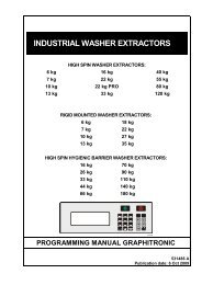
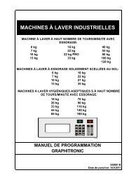
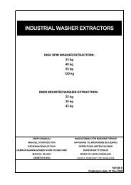
INDUSTRIAL CYLINDER HEATED DRYING<br />
IRONERS<br />
<strong>ROLLER</strong> <strong>DIAMETER</strong> <strong>350</strong>, <strong>500</strong> <strong>mm</strong><br />
IRONERS WITH INSERTION WIDTH:<br />
1400 <strong>mm</strong><br />
1600 <strong>mm</strong><br />
2000 <strong>mm</strong><br />
2<strong>500</strong> <strong>mm</strong><br />
3200 <strong>mm</strong><br />
IRONERS WITH FRONT / REAR DELIVERY WITH FOLDER OR WITHOUT<br />
FOLDER WITH INSERTION WIDTH:<br />
2000 <strong>mm</strong><br />
2<strong>500</strong> <strong>mm</strong><br />
3200 <strong>mm</strong><br />
INSTALLATIONS-, BRUGER- & VEDLIGEHOLDELSESVEJLEDNING<br />
531475 H<br />
Publication date: 13.5.2009
ANVISNING TIL MASKINENS BETJENING<br />
1. INDHOLDSFORTEGNELSE<br />
1. INDHOLDSFORTEGNELSE ......................................................................................... 1<br />
2. ADVARSLER OG SKILTE ............................................................................................ 2<br />
2.1. SKILTE ....................................................................................................................................................2<br />
2.2. ANVISNINGER TIL STRYGNING...........................................................................................................3<br />
2.3. MASKINENS IKKE KORREKTE BRUG........................................................................................................3<br />
2.4. INSTRUKTION TIL VEDLIGEHAALDELSE, JUSTERING OG SIKKERHED AF PERSONER.......4<br />
3. SYMBOLER PÅ BETJENINGSPANELET .................................................................... 5<br />
4. DRIFTS INSTRUKTIONER............................................................................................ 6<br />
4.1. START.......................................................................................................................................................6<br />
4.2. START AF STRØMFORSYNING.................................................................................................................6<br />
4.3. PROGRAMVALG .......................................................................................................................................6<br />
4.4. START AF STRYGNING.............................................................................................................................6<br />
4.5. OPVARMNINGSPROCES ..........................................................................................................................6<br />
4.6. STRYGNING..............................................................................................................................................6<br />
4.7. FOLDNING ................................................................................................................................................7<br />
4.8. PROGRAMÆNDRING UNDER STRYGNING..............................................................................................7<br />
4.9. STANDSNING AF STRYGNING..................................................................................................................7<br />
4.10. FREMGANGSMÅDE I TILFÆLDE AF FEJLMELDINGER...........................................................................7<br />
4.11. MASKINENS NØDSTOP ......................................................................................................................8<br />
4.12. UDTAGNING AF FASTKLEMT TØJ .....................................................................................................8<br />
4.13. STRØMAFBRYDELSE..........................................................................................................................8<br />
5. TABLE OF ERROR CODES, MESSAGES AND TROUBLESHOOTING ................... 9<br />
5.1. TROUBLESHOOTING ............................................................................................................................9<br />
5.2. SOLVING OF COMMON PROBLEMS ...................................................................................................9<br />
5.3. ERROR MESSAGES ..............................................................................................................................9<br />
5.4. HOW TO SOLVE ERROR MESSAGES .................................................................................................9<br />
5.5. TABLE OF ERROR MESSAGES............................................................................................................9<br />
5.6. EXPLANATION OF ERROR MESSAGES............................................................................................10<br />
531475_H_PUB_DATE_13_MAY_2009.DOC ANVISNING TIL MASKINENS BETJENING 1
2. ADVARSLER OG SKILTE<br />
DER BEDES AT LÆSE OG OVERHOLDE FØLGENDE INSTRUKTIONER FOR AT MINIMERE FARE FOR BRAND,<br />
ELULYKKE, ALVORLIG SKADE PÅ PERSONER ELLER MATERIELLE SKADER:<br />
– Denne manuals version er oversættelse fra engelsk original version. Disse henvisninger gælder ikke uden original<br />
version.<br />
– Forud for installation, brug og vedligeholdelse af maskinen læs venligst alle vejledninger, dvs. denne „Installations-,<br />
bruger- & vedligeholdelsesvejledning“, „Progra<strong>mm</strong>eringsmanualen“ og „Reservedelskataloget“ nøje.<br />
Progra<strong>mm</strong>eringsmanualen og Reservedelskataloget medfølger som standard ikke, men de kan fås hos<br />
forhandleren / producenten.<br />
– Følg anvisningerne i ovennævnte vejledninger og opbevar dem et egnet sted for senere opslag.<br />
– Maskinen må ikke betjenes af børn. Inden maskinen startes må De overbevise Dem om, at der i nærheden ikke er<br />
personer (børn) eller dyr. Maskinen må ikke sættes i gang, hvis der mangler nogle dele eller, hvis åbningerne ikke er<br />
lukkede. Uden grund må der ikke manipuleres med styringen. Maskinens version OPL (uden møntautomat) kræver<br />
kvalificeret personale.<br />
– Ved strygning skal man sætte fast løse klæder, slips, kæder, armbånd og langt hår.<br />
– Stoffer, som indeholder brandfarlige eller eksplosive midler må ikke sættes i maskinen. I nærheden af maskinen må<br />
ikke lagres brandbare ting. Hold maskinens overflage ren og uden brandbare materialer og fjern en gang om dagen<br />
den opsamlede støv fra filtrene. Dampene fra maskinen skal suges væk fra ru<strong>mm</strong>et.<br />
– Ved beskadigelsen af sikkerhedslisten, som beskytter fingrene, hold op med at stryge!<br />
– Start ikke maskinen med indsat håndtag til hånddrift.<br />
– Ved manipulation med det varme vasketøj brug beskyttende handsker.<br />
– Den ekvivalente støjniveau på betjeningsstedet er lavere end 70dB (A).<br />
TIL VERSION MED GASOPVARMNINGEN<br />
– Hvis man opdager, at der et eller andet sted i maskinen undslipper gas, lufter man ud, lukker for hovedtilførsel af<br />
gassen, tænder ingen elektriske forbrugere, ryger ikke bruger ikke åben ild og tilkalder mekanikeren.<br />
– Undgå at tage ud af drift eller ændre indstillinger af undertryksknap(per), af sikkerhedstermostat, af tilsugning af<br />
primær luft og på alle apparater, som er indstillet fra fabrikken.<br />
TIL VERSION MED DAMPOPVARMNING<br />
– Hvis man opdager, at der et eller andet sted i maskinen undslipper damp. Stands hovedtilførslen og kald på<br />
mekanikeren.<br />
2.1. SKILTE<br />
ADVARSEL!<br />
Maskinen frakobles fra strømtilførsel før der foretages hvad som helst indgreb i maskinen.<br />
Maskinen er uden spænding såfremt hovedstik er taget ud fra nettets stikkontakt eller såfremt<br />
hovedtilførsel frakobles.<br />
Ved slukket hovedafbryder er tilgangskle<strong>mm</strong>erne på maskinens hovedafbryder under<br />
spænding!<br />
Tryk på fare tasten Den betegnede flade må ikke røres ester<br />
maskinens opvarmning<br />
Giv agt! Det elektriske anlægs farlige Ved manipulation med vasketøjet må der ikke<br />
elektriske spænding gribes ind i det betegnede rum<br />
Den ikke rigtige og den riftige og den rigtige udbre-delse af vasketøjet på maskinens tilsætningsbånd<br />
Strygemaskine, Strygemaskine med udgang Strygemaskine med udgang på begge<br />
på begge side uden sa<strong>mm</strong>enlægger side med sa<strong>mm</strong>enlægger<br />
2 ANVISNING TIL MASKINENS BETJENING 531475_H_PUB_DATE_13_MAY_2009.DOC
2.2. ANVISNINGER TIL STRYGNING<br />
Maskinen er kun beregnet til strygning af glat vasketøj (flad vasketøj, sengetøj, duge, viskestykker,<br />
håndduge, lo<strong>mm</strong>ertørklæder og andre slags af mindre og fladt vasketøj) fremstillet af linned, bomuld, uld,<br />
silke, polyakryl - og polyestertråd. Tørretumbleren med tosidig udgang med foldemaskinen er oven i købet<br />
bestemt til sa<strong>mm</strong>enlægning af vasketøj i længderetning, såfremt tøjets mål gør det muligt, mindst én gang<br />
at sa<strong>mm</strong>enlægge det i længderetning.<br />
Maskinens fremstiller har ingen ansvar for beskadigelse af tøjet ved utilpassende strygning.<br />
Maskinen er ikke beregnet til strygning af tøj, som indeholder dele fra metal, plastic, glasfibre eller<br />
skumgu<strong>mm</strong>i.<br />
I strygemaskinen kan indføres tøj med optimal restfugtighed på 40±10%. Strygemaskinen foretager<br />
slutudtørring. Vasketøjet med højere restfugtighed skal centrifugeres eller fortørres. Vasketøj der er for tør<br />
skal gøres våd inden strygning for at undgå vasketøjets tilklæbning på strygebane og sa<strong>mm</strong>enlæggnings<br />
strygevalse. Vasketøjet skal skylle grundigt under vaskeprocessen. Er denne betingelse ikke opfyldt, kan<br />
tøjet gulne eller der kan blive rester af vaskemidler og urenheder på tøjet. Tøjet skal sorteres i henhold til<br />
tekstilart og til den ønskede strygetemperatur. Lo<strong>mm</strong>erne udtø<strong>mm</strong>es, fre<strong>mm</strong>ede legemer, f. eks. nåle, søm,<br />
skruer osv., som kunne beskadige både tøjet og maskinen, fjernes fra tøjet.<br />
Husk at rense støvfilter én gang om dagen.<br />
– Låget på maskinens støvfilter (støvfiltre) åbnes og filtret tages ud. Check støvfiltrets tilstand og fjern<br />
aflejret støv. Giv filtret, som nu er fri for urenheder, tilbage på dets plads og luk låget igen.<br />
Tøjet stilles på indføringsbånd én gang til venstre og én gang til højre eller fra venstre til højre, for at valsen<br />
belastes jævnt ved varmeudstråling.<br />
Advarsel for model med udgang på begge side med sa<strong>mm</strong>enlægger: kun vasketøj der passerer<br />
midten af strygevalse bliver lagt sa<strong>mm</strong>en.<br />
Tøj med knapper lægges med knapper opad for at knapper kunne trækkes ind i ballen.<br />
Husk at være mere forsigtig under strygning af syntetiske stoffer, for at undgå at stoffer klæbes ved valsen.<br />
Lad aldrig tøjet i maskinen!<br />
Minimal svingning af temperatur kan påvirkes v. h. a. uddannet betjening, som på grund af tøjets art og dets<br />
restfugtighed regulerer den indstillede temperatur og strygehastighed på maskinens betjeningspanel. Vil<br />
man opnå strygemaskinens maksimale ydelse, anbefales der:<br />
– at forebygge temperaturens fald ved at stryge korrekt<br />
– at sikre kontinuitet af strygeprocessen: jo mere flydende, desto bedre<br />
– at afkorte tider, når man ikke stryger på maskine med arbejdstemperatur<br />
– at gruppere tøjets stykker efter stoffets sa<strong>mm</strong>ensætning eller efter restfugtighed<br />
– at tilpasse hastighed og temperatur efter specifikke behov ved hver strygeproces<br />
2.3. MASKINENS IKKE KORREKTE BRUG<br />
!<br />
ADVARSEL !<br />
DENNE MASKINE BLEV KONSTRUERET TIL INDUSTRISTRYGNING OG TØRRING, HHV. OGSÅ FOLDNING<br />
AF JÆVNT TØJ, SOM BLEV VASKET I VAND. HVAD SOM HELST ANDEN BRUG SOM IKKE SVARER TIL<br />
DEN HER ANFØRTE VIL UDEN PRODUCENTENS SKRIFTLIGE TILLADELSE ANSES SOM IKKE KORREKT<br />
BRUG.<br />
– Undgå at bruge tilbageløb til noget andet end til frigøring af person eller fastklemt effekt.<br />
– Undgå at stryge tøjet hvis sa<strong>mm</strong>ensætning er til hinder til fugtigheds tilbageholdning.<br />
– Stryg aldrig når tøjet ikke er fordelt afvekslende på strygeområdets højre og venstre side.<br />
– Stands aldrig maskinen ved at afbryde dens strømforsyning, hvis maskinens temperatur er højere end på<br />
80°C, undtagen ekstraordinære tilfælde.<br />
– Undgå at lade for stort frit område i valsens hele bredde under strygning af små stykker.<br />
– Undgå at lade maskinen køre på maksimal hastighed under opvarmning og afkøling.<br />
– Undgå at standse maskinen, når strygebånd ikke er helt tørre. Undgå at stryge ved temperaturer, som er<br />
lavere end på 80°C, for det kan medføre oxidering på valsen.<br />
– Undgå at indføre i strygemaskinen tøj, der indeholder for hårde komponenter, som kunne beskadige<br />
valsens overflade eller bånd.<br />
– Undgå at stryge syntetiske stoffer ved høje temperaturer.<br />
531475_H_PUB_DATE_13_MAY_2009.DOC ANVISNING TIL MASKINENS BETJENING 3
2.4. INSTRUKTION TIL VEDLIGEHAALDELSE, JUSTERING OG<br />
SIKKERHED AF PERSONER<br />
De følgende instruktioner er ikke naevnt i denne vejledning „Manual til maskins betjening“. Disse instruktioner søg<br />
venligst i „Manual til instalation og vedligehaaldelse“ som følger med maskinen. . Henvisninger til „Vejledning til<br />
instalation og vedligehaaldelse“ i.h.t. norm EN ISO 10472-1 (-5):<br />
1. Information vedr. vejlednings ydelse<br />
2. Maskinanvendelses omfang og begraensning<br />
3. Vedligehaaldelse og justering<br />
4. Ventilation<br />
5. Skaerm<br />
6. Fejl, rensning, vedligehaaldelse<br />
7. Varme risici<br />
8. Udsugning<br />
9. Manipulation, instalation<br />
10. Udskifning af oppakning<br />
11. Indtraek steder, vedhaeftning<br />
4 ANVISNING TIL MASKINENS BETJENING 531475_H_PUB_DATE_13_MAY_2009.DOC
3. SYMBOLER PÅ BETJENINGSPANELET<br />
Betjeningspanel af<br />
strygemaskine<br />
Strygemaskines betjeningsbord<br />
med udgang på begge side med<br />
sa<strong>mm</strong>enlægger<br />
Fig. 3.A. Betjeningspaneler<br />
Strygemaskines betjeningsbord<br />
med udgang på begge side<br />
uden sa<strong>mm</strong>enlægger<br />
A = Øvre display – hos version OPL vises her nu<strong>mm</strong>er på program, hos møntversion vises der den<br />
resterende tid<br />
B = Den nedeste display – viser temperatur, hastighed og for strygemaskine med udgang på begge side og<br />
sa<strong>mm</strong>enlægger også antalet af sa<strong>mm</strong>enlæggninger eller sa<strong>mm</strong>enlæggnings brede<br />
C = stikkort – jf. „Progra<strong>mm</strong>erings manual“<br />
START<br />
– til strygemaskinens start<br />
PROGRAMVALG (kun OPL)<br />
– for strygnings programvalg, gælder<br />
strygninsmaskine med udgang på begge side<br />
og anlæg til sa<strong>mm</strong>enlæggning er ydemere<br />
ekstra trykknaper<br />
TILBAGELØB (kun OPL)<br />
– til strygemaskinens stop<br />
– til start af tilbageløb<br />
AUTOMATISK STANDSNING AF STRYGNING<br />
– version OPL: til maskinens afkøling og automatisk<br />
standsning<br />
– møntversion: til standsning af indføringsbånd<br />
og til opvarmnings stop<br />
– til bekræftelse af fejlmeldinger<br />
MASKINE MED FOLDEUDSTYR RÅDER VIDERE OVER DISSE KNAPPER:<br />
FOLDNING TIL FAST ANTAL FOLDER<br />
– til valg af foldning til fast antal folder<br />
– til at indtaste antal folder<br />
FOLDNING TIL FOLDENS FASTSATTE<br />
BREDDE<br />
– til valg af foldning til foldens fastsatte bredde<br />
– til at indtaste foldens bredde<br />
Fig. 3.B. Symboler på betjeningspanel<br />
TEMPERATUR (kun OPL)<br />
– til temperaturens visning / indstilling<br />
HASTIGHED (kun OPL)<br />
– til hastighedens visning / indstilling<br />
PLUS, MINUS (kun OPL)<br />
– til værdiens forhøjning / nedsættelse<br />
GEM PROGRAM ? (kun OPL)<br />
– til at ge<strong>mm</strong>e indstillede parametre i<br />
huko<strong>mm</strong>else på begge side uden<br />
FOLDEPROCES JA/NEJ<br />
– til start / stop af foldeprocessen<br />
LIGEVÆGTSRETNING<br />
– til valg af ligevægtsretning gælder<br />
også for strygemaskine med<br />
udgang på begge side uden<br />
sa<strong>mm</strong>enlægger<br />
531475_H_PUB_DATE_13_MAY_2009.DOC ANVISNING TIL MASKINENS BETJENING 5
4. DRIFTS INSTRUKTIONER<br />
4.1. START<br />
Før maskinens første start skal checkes om maskinen er installeret korrekt – jf. „Manualen til maskinens<br />
opstilling og vedligeholdelse ”. Check tilstand af støvfilter og af andre maskinens dele efter „Manualen til<br />
maskinens opstilling og vedligeholdelse“.<br />
4.2. START AF STRØMFORSYNING<br />
Hovedafbryder bagest på strygemaskinens venstre stativ tændes i position markeret med „ I “ – displayet<br />
begynder at lyse.<br />
4.3. PROGRAMVALG<br />
Version OPL: tryk på knap „SELECT“ for at vælge program. Så kan ved hjælp af knap „SELECT“ eller „+“<br />
øges og ved hjælp af knap „-“ formindskes programnu<strong>mm</strong>er på øvre display. Det valgte program vil<br />
downloades først 2 s efter det sidste tryk på en af fornævnte knapper (hermed undgås f. eks. pludselige<br />
hastigheds ændringer ved programvalg under maskinens drift).<br />
Møntversion: programvalg står ikke til rådighed, maskinen kører kun med ét program.<br />
Arbejdstemperatur vælges i henhold til strøget tøj efter følgende tabel:<br />
TEMPE-RATUR<br />
(°C)<br />
MATERIALE<br />
85 Polyacryl, polyamid<br />
110 Polyester, cellulose<br />
135 Silke<br />
170 Uld<br />
170 Bomuld<br />
175 Hør<br />
4.4. START AF STRYGNING<br />
Version OPL: tryk på knap „START“ – maskinen startes, dvs. der startes valsens drev, ventilator<br />
(ventilatorer), opvarmning og kobling til drev af indføringsbånd (såfremt maskinen er udstyrt med koblingen).<br />
Møntversion: indkast nødvendigt antal mønter i møntkasse (på displayet vises betalt strygetid i minutter) og<br />
tryk på knap „START“ – der startes valsens drev, ventilator (ventilatorer) og opvarmning, men der startes<br />
ikke kobling til drev af indføringsbånd.<br />
4.5. OPVARMNINGSPROCES<br />
Efter maskinens start skal ventes indtil strygevalsen er opvarmet til den ønskede temperatur. Der tjekkes<br />
ligeledes pressostater inden opvarmningens start.<br />
Version OPL: opvarmningsproces kan vises på nedre display hvis man trykker på knap for temperatur.<br />
Version med møntindkast: slut af opvarmningsprocessen signaliseres ved sirenens intermitterende lyd. I<br />
dette øjeblik begynder nedtælling af den betalte strygetid.<br />
PAS PÅ: forsøger kunde at stryge før opvarmningsprocessens slut (ved at stikke tøj under<br />
beskyttelseskant), begynder betalt tid at løbe med det sa<strong>mm</strong>e og akustisk signal lyder.<br />
4.6. STRYGNING<br />
Version OPL: strygning kan startes, når aktuel temperatur ligger nær ved den ønskede temperatur for den<br />
bestemte art af tøj. Check om stoffet tåler strygning og hvis ja, ved hvilken temperatur. Temperaturens og<br />
hastighedens værdier kan under strygning tilpasses efter behov – jf. „Progra<strong>mm</strong>erings manual“.<br />
Version uden møntindkast: strygning kan startes, når sirenen begynder at lyde – start indleverings bånd ved at<br />
træde på pedalen. Under strygningen kan man til enhver tid forlænge den betalte strygetid ved indkast af<br />
yderligere mønter. Et minut før udløb af den betalte tid aktiveres sirenen (i 10 sekunder) for at informere<br />
betjeningspersonalet om den betalte tids slut.<br />
Indføringsbånd kan ved hjælp af fodpedal stoppes,<br />
fig. 4.6.A, pos. 3, og startes, pos. 2, for at kunne<br />
indføre tøjet korrekt i strygemaskinen. Er tøjet ikke<br />
indført korrekt, brug tilbageløb for at opnå dets<br />
frigøring.<br />
DENNE PROCES KAN KUN GENNEMFØRES<br />
FOR SÅ LANG TID, SOM ER ABSOLUT<br />
NØDVENDIG TIL TØJETS UDTAGNING!<br />
Fig. 4.6.A<br />
6 ANVISNING TIL MASKINENS BETJENING 531475_H_PUB_DATE_13_MAY_2009.DOC
Version OPL: ved at trykke på knappen for tilbageløb kan maskinen standses og ved at trykke på denne<br />
knap én gang til startes valsens rotation i den modsatte retning for en afgrænset tid. Tilbageløbets varighed<br />
forlænges ved at trykke på knappen gentagne gange.<br />
Møntversion: tilbageløb startes ved at trykke på beskyttelseskant, jf.. 4.6.A,<br />
pos. 1.<br />
Tørt og strøget tøj føres tilbage til aftagnings trug, fig. 4.6.A, pos. 5 og kan<br />
straks foldes.<br />
VERSION OPL: HUSK AT TRYKKE UNDER STRYGNING I<br />
TILSTRÆKKELIGT LANG TID FØR AFBRYDELSE AF TØJINDFØRING I<br />
MASKINEN PÅ KNAP FOR AUTOMATISK STRYGESTOP, FOR AT UNDGÅ<br />
VALSENS OVERHEDNING.<br />
Fig. 4.6.B<br />
! ADVARSEL (KUN VERSION OPL)!<br />
I TILFÆLDE AF FARE FOR PERSONER STANDS MASKINEN VED AT TRYKKE PÅ CENTRALSTOP ELLER<br />
PÅ BESKYTTELSESKANT.<br />
4.7. FOLDNING<br />
Gælder for strygemaskine med udgang på begge side med sa<strong>mm</strong>enlægger.<br />
Foldning foretages på grund af programparametre og i henhold til målet længde på det sidste tøj. Det første<br />
tøjstykke som stryges efter maskinens start eller efter programveksel kan derfor blive foldet forkert eller kan<br />
heller ikke blive foldet.<br />
Der anbefales at sortere tøj før strygningen i henhold til dets størrelse for at kunne opnå gode resultater.<br />
Skal foldeudstyr fungere rigtigt, er det ved tøjindføring nødvendigt at lade et mellemrum på min. 15÷20 cm<br />
mellem enkelte tøjstykker (afhængig af strygnings hastighed), for ellers kan foldes flere stykker på<br />
hinanden.<br />
Under strygning af tøj som er snæver end valsens bredde skal tøjet lægges afvekslende til venstre og til<br />
højre for at undgå overhedning af strygevalsens rande. Er tøjets bredde mindre end halvdelen af maskinens<br />
bredde, vil tøjet ikke foldes!<br />
4.8. PROGRAMÆNDRING UNDER STRYGNING<br />
Gennemføres på den sa<strong>mm</strong>e måde som før strygnings start– jf. kapitel 4.3 (kun version OPL).<br />
4.9. STANDSNING AF STRYGNING<br />
Version OPL: foretages ved hjælp af knap for automatisk strygnings stop. Trykker man på denne knap,<br />
stoppes der opvarmning og LED-kontrollampe ved siden af denne knap begynder at blinke. Så snart<br />
temperatur falder under 80°C, standses maskinen helt. Der er kun styresystemet som er tilsluttet elstrøm.<br />
Maskinens komplette slukning skal foretage ved hjælp af hovedafbryder. Valsens afkøling kan fremskyndes<br />
hvis man stryger et par stykker tøj med større fugtighed end på 50%.<br />
! ADVARSEL !<br />
ER STRYGEVALSENS TEMPERATUR HØJERE END PÅ 80°C, STANDS ALDRIG MASKINEN VED HJÆLP AF<br />
HOVEDAFBRYDER ELLER AF CENTRALSTOP ELLER AF SIKKERHEDSKANT! DER ER FARE FOR<br />
BESKADIGELSE AF STRYGEBÅND!<br />
Møntversion: efter udløb af betalt tid standses opvarmning og maskinen overgår i afkølingsprocessen. Så<br />
snart temperaturen falder under 80°C, stopper maskinen automatisk helt. I løbet af afkølingsprocessen kan<br />
normal strygning startes til enhver tid på ny ved at indkaste videre mønter og ved at trykke på knappen Start<br />
(jf. 4.4. Start af strygning).<br />
4.10. FREMGANGSMÅDE I TILFÆLDE AF FEJLMELDINGER<br />
Fejlmelding vises på nedre display i form af et nu<strong>mm</strong>er (001 til 999), på øvre display vises samtidigt „Er“, i<br />
nogle tilfælde begynder yderligere akustisk signal at lyde. Såfremt det er muligt, arbejder strygemaskinen<br />
også i tilfælde af fejlmelding videre, dog opvarmning er lukket.<br />
!<br />
ADVARSEL !<br />
STANDSER STRYGEMASKINEN VED EN HØJERE TEMPERATUR END PÅ 80°C, ER DET NØDVENDIGT AT<br />
SIKRE STRYGEVALSENS AFKØLING VED HJÆLP AF VÅDT TØJ OG VIA MANIPULERING MED<br />
HÅNDSVING.<br />
Fejlmelding kan slettes og akustisk signal kan stoppes ved at trykke på knap for automatisk strygestop,<br />
hos møntversion også ved at trykke på knappen „START“. Dog såfremt fejlen består videre, vises<br />
fejlmelding igen om 30 s.<br />
Yderligere detaljerede oplysninger – jf. „Progra<strong>mm</strong>erings manual“.<br />
531475_H_PUB_DATE_13_MAY_2009.DOC ANVISNING TIL MASKINENS BETJENING 7
4.11. MASKINENS NØDSTOP<br />
Kun version OPL.<br />
Opstår der fare for betjenings sikkerhed eller helbred, kan maskinen stoppes ved at<br />
trykke på knappen for centralstop, fig. 4.11. på strygemaskinens stativ eller ved at<br />
trykke på beskyttelseskant,<br />
fig. 4.6.A, pos. 1. Fig. 4.11.<br />
! ADVARSEL !<br />
SÅ SNART ÅRSAGEN FOR MASKINENS STANDSNING FJERNES, TAG TØJET UD FRA MASKINEN OG KØL<br />
VALSEN AF TIL TEMPERATUR PÅ UNDER 80° C (MANUELT VED HÅNDSVING ELLER GENNEM<br />
MASKINENS LØB). BRANDFARE!<br />
4.12. UDTAGNING AF FASTKLEMT TØJ<br />
Er tøjet fastklemt i maskinens indre, sluk for maskinen ved<br />
hjælp af hovedafbryder og tag fat i håndsving placeret på<br />
maskinens højre stativ. Håndsvinget klappes af og trykkes i<br />
hul. Drej på håndsving og tryk det i retning mod stativ under<br />
drejningen. Efter tøjets frigøring håndsvinget løsnes og klappes<br />
tilbage i dets grundstilling.<br />
Fig. 4.12.A<br />
!<br />
ADVARSEL !<br />
BENYTTELSE AF HÅNDSVING KAN RESULTERE I ALVORLIG PERSONSKADE HVIS DET ER TRYKKET I<br />
HUL OG VALSEN ROTERER I TILBAGELØB.<br />
4.13. STRØMAFBRYDELSE<br />
! ADVARSEL !<br />
ER VALSENS TEMPERATUR HØJERE END PÅ 80°C , ER DET NØDVENDIGT AT KØLE VALSEN AF VED<br />
DENS DREJNING (MANUELT- VED HÅNDSVING ELLER GENNEM MASKINENS GANG). BRANDFARE!<br />
Manipulering med håndsving efter kapitel 4.12.<br />
Fungerer strømforsyning igen, kan maskinen startes med det sa<strong>mm</strong>e.<br />
Møntversion: er valsens temperatur efter fornyelse af strømforsyning højere end på 80°C, tryk på knappen<br />
„Start“ – herved startes strygevalsens drev og grundet dette undgås beskadigelse af strygebånd (der er<br />
ikke nødvendig at indkaste mønter). Falder temperatur til under 80°C, standser maskinen automatisk.<br />
8 ANVISNING TIL MASKINENS BETJENING 531475_H_PUB_DATE_13_MAY_2009.DOC
5. TABLE OF ERROR CODES, MESSAGES<br />
AND TROUBLESHOOTING<br />
5.1. TROUBLESHOOTING<br />
Control system ensures complete control of the ironer. When a failure occurs, the machine will go automatically<br />
to safety state.<br />
Following table is a guide for solving of co<strong>mm</strong>on problems.<br />
5.2. SOLVING OF COMMON PROBLEMS<br />
Problem Cause / state Problem solving<br />
After switching ON the main<br />
switch, the display doesn’t<br />
light up.<br />
The machine doesn’t react<br />
when pressing the buttons on<br />
keyboard<br />
• Failure in power supply<br />
• Some of emergency stops is<br />
pushed in (the buzzer<br />
sounds in this case)<br />
• The fuse in distributor or on<br />
the control system is blown<br />
• No button functions<br />
• Safety bar or crank for<br />
manual rotation is pushed in<br />
(the button „Start“ doesn’t<br />
work)<br />
• Check outer supply<br />
• Deactivate (pull out) both<br />
emergency stops<br />
• Change the fuse; if it blows<br />
again, then the failure is in<br />
electrical installation<br />
• Find out, if connector „S1“ of<br />
keyboard is connected properly<br />
• Loosen the bar and crank,<br />
check, if micro switch of safety<br />
bar or crank is not ja<strong>mm</strong>ed<br />
5.3. ERROR MESSAGES<br />
It a failure occurs, the control system displays an error message and the siren will whistle discontinuously<br />
in some cases.<br />
5.4. HOW TO SOLVE ERROR MESSAGES<br />
Find appropriate error message in manual.<br />
Error message can be delete by pressing the button for automatic finishing of ironing.<br />
5.5. TABLE OF ERROR MESSAGES<br />
No. Error message Machine operation<br />
001* Temperature of ironing roller is higher than 200°C Machine operates normally, heating is OFF<br />
002*<br />
Temperature of ironing roller is higher than<br />
80°C and roller does not rotate<br />
Machine is stopped, it is possible to start it by<br />
the button „Start“<br />
003 Overloading of motor(s) of ventilator(s)<br />
Machine changes to mode of automatic<br />
finishing of ironing<br />
Machine goes on operating, heating is OFF.<br />
004 Short circuit of temperature sensor<br />
Stopping the machine is possible only<br />
by the main switch.<br />
Machine goes on operating, heating is OFF.<br />
005* Disconnection of temperature sensor<br />
Stopping the machine is possible only by the<br />
main switch.<br />
006 Failure of drive Machine is stopped<br />
007<br />
Underpressure switches are off<br />
(gas heating only)<br />
Machine is operating, heating is OFF<br />
008 Failure of burner ignition (gas heating only) Machine is operating, heating is OFF<br />
009<br />
Crank for manual rotation of ironing cylinder is<br />
pushed<br />
Machine is stopped<br />
010<br />
Lifting up the trough (only machines with ironer<br />
with front/rear delivery)<br />
The machine operates normally, direction<br />
of balancing is switched forward, speed<br />
is reduced to minimum<br />
011 Failure of underpressure switches Machine is operating, heating is OFF<br />
012 Wrong function of safety bar<br />
Machine control is blocked, machine can be<br />
switched off only<br />
013 Defective speed sensor (IF machines only) Machine is running without folding<br />
255 See error No. 005 -<br />
* = Message is accompanied with discontinuous sound of siren<br />
531475_H_PUB_DATE_13_MAY_2009.DOC ANVISNING TIL MASKINENS BETJENING 9
5.6. EXPLANATION OF ERROR MESSAGES<br />
IMPORTANT!<br />
TECHNICAL REPAIRS OF IRONER CAN BE EXECUTED ONLY BY TECHNICIANS WITH APPROPRIATE<br />
KNOWLEDGE OF THE MACHINE.<br />
ERROR 1: TEMPERATURE OF IRONING <strong>ROLLER</strong> IS HIGHER THAN 200°C<br />
Error is detected by temperature sensor. For higher safety the machine is equipped with separate safety<br />
thermostat, which disconnects heating when temperature exceeds 210°C.<br />
CAUSE:<br />
1. Interruption of ironing when temperature<br />
of ironing roller is high (180°C)<br />
Wait until the machine cools down, or cool it down<br />
by ironing of wet linen (use some old linen as it<br />
can be damaged by the high temperature)<br />
2. Failure of electrical installation Professional servicing is necessary<br />
3. Interruption of temperature sensor<br />
(displayed temperature is 255°C)<br />
Change temperature sensor, check the connection<br />
of the sensor<br />
ERROR 2: TEMPERATURE OF IRONING <strong>ROLLER</strong> IS HIGHER THAN 80°C<br />
AND THE <strong>ROLLER</strong> IS NOT ROTATING<br />
Rotation of ironing roller is evaluated on the basis of signal from frequency inverter. If the roller stops due to<br />
any cause (it means either on purpose, e.g. by the button for reverse operation, by pushing the crank or safety<br />
bar, or due to failure), then after 5s the siren starts whistling to warn about danger – burning of ironing belts.<br />
CAUSE:<br />
1. Pressing the button for reverse operation Press the button again for starting the reverse<br />
operation or press „Start“ again to start the normal<br />
operation.<br />
2. The crank for manual rotating of the roller was Start the normal operation by the button „Start“.<br />
pushed<br />
When it is not possible, check, whether the crank<br />
is not ja<strong>mm</strong>ed in the insertion position, or the micro<br />
switch got ja<strong>mm</strong>ed on the crank (inside the stand).<br />
3. The safety bar was pushed Start the normal operation by the button „Start“.<br />
4. Failure of drive Switch the machine OFF and ON again. If it’s not<br />
possible to start it even now, cool it down by wet<br />
linen and rotating the handle. After cooling the<br />
machine down below 80°C, repair the drive.<br />
ERROR 3: OVERLOADING OF VENTILATOR(S) MOTOR(S)<br />
The machine is equipped with one, and at length 250 and 320 cm with two ventilators for exhaust of<br />
evaporated humidity, or combustion gases from the gas burner. In motor winding of every ventilator there is<br />
placed bimetal that detects overheating of the winding.<br />
CAUSE:<br />
4. Mechanical failure of ventilator Check ventilator(s).<br />
5. Clogged exhaust pipeline Check and clean exhaust pipeline.<br />
ERRORS 4 AND 5: SHORT CIRCUIT / INTERRUPTION OF TEMPERATURE SENSOR<br />
Temperature sensor of ironing roller is pushed on the roller approximately in 1/3 of its length and it is<br />
equipped with cable with silicone insulation, which withstands high temperatures of ironing roller without<br />
problems. When the failure occurs, the sensor must be changed (repair is not possible).<br />
ERROR 6: FAILURE OF DRIVE<br />
Failure of the drive is evaluated on the basis of signal from frequency inverter.<br />
CAUSE:<br />
1. Failure message of frequency inverter Try to switch the machine OFF and ON again, or<br />
let the inverter cool down. If it doesn’t help, look<br />
for error according to individual instruction for<br />
inverter.<br />
10 ANVISNING TIL MASKINENS BETJENING 531475_H_PUB_DATE_13_MAY_2009.DOC
ERROR 7: UNDER PRESSURE SWITCHES ARE OFF (GAS HEATING ONLY)<br />
1 or 2 (according to width of machine) under pressure sensors detect correct function of combustion gases<br />
exhaust. If the combustion gases exhaust is weak and there is a danger of spreading combustion gases to<br />
the space around ironer, then under pressure switches will open and by this the gas valve gets closed and<br />
the burner will turn off.<br />
CAUSE:<br />
1. Clogged exhaust pipeline, dust in ventilator Check and clean the whole route of combustion<br />
vanes, etc.<br />
gases exhaust.<br />
2. Ventilator is not rotating at all. Check motor of ventilator and electrical installation,<br />
see also error 003.<br />
ERROR 8: FAILURE OF BURNER IGNITION (GAS HEATING ONLY 50 HZ)<br />
Ironer is equipped with automatic electronic system for the burner ignition and the flame guarding.<br />
If the flame ignition is not successful, the system will bring out the error message. After confirmation this message<br />
by the button for automatic finishing of ironing, a new trial to ignite the burner will be executed.<br />
CAUSE:<br />
1. Gas supply is closed Open the valve installed on the gas pipeline to<br />
ironer.<br />
2. Defect gas valve (in the ironer stand) Check the valve. Switching of the valve is<br />
accompanied by audible click.<br />
3. Wrong function of mixer Remove sieve of mixer and check, whether the jet<br />
is not clogged and whether the sleeve above jet is<br />
in correct height (see Maintenance manual).<br />
4. Wrong position of ignition electrode Check, whether the electrode is covered with flame<br />
when the burner is burning.<br />
5. Defective ignition electrode Check, whether the electrode glows.<br />
ERROR 9: CRANK FOR MANUAL ROTATION OF IRONING CYLINDER IS PUSHED<br />
To avoid injury when pressing the crank during reverse operation, the crank is equipped with a safety<br />
switch, which will stop the ironer when the crank is pushed. Then this error message is displayed.<br />
CAUSE:<br />
1. The crank is pushed Release the crank and start the machine with<br />
„Start“ button or start reverse operation<br />
2. Micro switch on the crank stayed activated Check the correct function of the micro switch<br />
ERROR 10: THE TROUGH IS LIFTED UP (ONLY MACHINES WITH FRONT/REAR<br />
DELIVERY)<br />
Position of the trough is monitored to avoid an access into the machine inner space during operation.<br />
If the trough opens during the machine operation, the error message is displayed and the machine changes<br />
to safety condition (direction of balancing is switched forward, speed is reduced to minimum). After the trough<br />
is closed, the error message is deleted, original speed as well as direction of balancing are reset.<br />
CAUSE:<br />
1. Trough is lifted up Close the trough<br />
2. Micro switch of trough position is damaged Check the correct function of the micro switch<br />
ERROR 11: FAILURE OF UNDERPRESSURE SWITCHES<br />
The correct function of underpressure switches is checked during the machine operation. Before starting<br />
the machine by the button „START“, the switches must be switched OFF. They must be switched ON within<br />
10s after START. See failure 007.<br />
CAUSE:<br />
1. Failure in wiring Check the correct wiring of switches<br />
2. Defected underpressure switch Check the switch correct function<br />
531475_H_PUB_DATE_13_MAY_2009.DOC ANVISNING TIL MASKINENS BETJENING<br />
11
ERROR 12: WRONG FUNCTION OF SAFETY BAR<br />
When the machine is switched on, the correct function of safety bar is checked. In case of wrong function the error<br />
012 is reported. The machine control is blocked and it is possible just to switch the machine off and eliminate<br />
the failure.<br />
CAUSE:<br />
1. Ja<strong>mm</strong>ed bar or switch Release the bar or switch<br />
2. Damaged switch Check correct function of the switch<br />
3. Failure in connection Check the correct switch connection<br />
4. Incorrect version of software or progra<strong>mm</strong>er The software version 1.40 or inferior must be used<br />
on machines made till June 2005, while the<br />
software version 1.42 or superior and progra<strong>mm</strong>er<br />
with revision E and superior must be used on machines<br />
which were made later.<br />
ERROR 13: DEFECTIVE SPEED SENSOR<br />
During the machine operation the correct function of speed sensor is checked. In case of incorrect function the error<br />
013 is reported.<br />
CAUSE:<br />
1. Damaged sensor Check the correct function of sensor<br />
2. Wrong adjustment of sensor Adjust distance between the sensor and rotating<br />
screen with teeth, so that the light indicator on<br />
sensor is blinking when the screen rotates.<br />
If the indicator is constantly ON, increase<br />
the distance, if it is constantly OFF, reduce<br />
the distance. If adjustment of diameter does not<br />
help, it is necessary to change the sensor.<br />
12 ANVISNING TIL MASKINENS BETJENING 531475_H_PUB_DATE_13_MAY_2009.DOC
INSTALLATION AND MAINTENANCE MANUAL<br />
1. TABLE OF CONTENTS<br />
1. TABLE OF CONTENTS ................................................................................................ 1<br />
2. WARNING AND LABELS ............................................................................................. 3<br />
2.1. MACHINE SYMBOLS..............................................................................................................................4<br />
3. TECHNICAL INFORMATION........................................................................................ 5<br />
3.1. IRONER USE...........................................................................................................................................5<br />
3.2. MACHINE DESIGN..................................................................................................................................5<br />
3.3. NAME PLATE ..........................................................................................................................................6<br />
3.4. IRONING MACHINE WITH <strong>ROLLER</strong> 35 CM ..........................................................................................6<br />
3.5. IRONING MACHINE WITH <strong>ROLLER</strong> 50 CM ........................................................................................10<br />
3.6. IRONING MACHINE WITH FRONT/REAR DELIVERY ........................................................................14<br />
4. INSTALLATION........................................................................................................... 18<br />
4.1. MANIPULATION AND UNPACKING.....................................................................................................18<br />
4.2. WORKSTATION REQUIREMENTS ......................................................................................................20<br />
4.3. MACHINE POSITIONING ON THE FLOOR..........................................................................................22<br />
4.4. ELECTRICAL CONNECTION ...............................................................................................................23<br />
4.5. EXHAUST SYSTEM ..............................................................................................................................28<br />
4.6. STEAM CONNECTION FOR STEAM HEATING ..................................................................................30<br />
4.7. GAS CONNECTION FOR GAS HEATING............................................................................................32<br />
4.8. CONVERSION TO ANOTHER GAS .....................................................................................................35<br />
4.9. MACHINE PREPARATION TO OPERATION .......................................................................................35<br />
5. MAINTENANCE AND ADJUSTMENTS...................................................................... 36<br />
5.1. SAFETY INSTRUCTIONS FOR MAINTENANCE.................................................................................36<br />
5.2. <strong>ROLLER</strong>.................................................................................................................................................36<br />
5.3. UNSTICKER ..........................................................................................................................................37<br />
5.4. IRONING BELTS ...................................................................................................................................37<br />
5.5. FEEDING BELTS / FEEDING TABLE ...................................................................................................39<br />
5.6. PRESSURE <strong>ROLLER</strong> PADDING ..........................................................................................................41<br />
5.7. RIBBONS...............................................................................................................................................41<br />
5.8. BEARING HOUSES...............................................................................................................................41<br />
5.9. CHAIN GEARS ......................................................................................................................................41<br />
5.10. MANUAL DRIVE GEAR.......................................................................................................................42<br />
5.11. GEAR BOXES (FIG.5.11.A) ................................................................................................................42<br />
5.12. FILTERS ..............................................................................................................................................44<br />
5.13. INDUCTIVE SENSOR OF TURNS......................................................................................................45<br />
5.14. OUTPUT SYSTEM ..............................................................................................................................45<br />
5.15. ELECTRIC INSTALLATION AND REPAIR .........................................................................................47<br />
5.16. FUSES .................................................................................................................................................47<br />
5.17. SAFETY THERMOSTAT .....................................................................................................................48<br />
5.18. FREQUENCY INVERTER ...................................................................................................................48<br />
5.19. GAS INSTALLATION MAINTENANCE ...............................................................................................48<br />
5.20. UNDERPRESSURE SWITCH - GAS HEATING .................................................................................48<br />
5.21. LAUNDRY ROOM EARTH LEAKAGE TRIP .......................................................................................50<br />
531475_H_PUB_DATE_13_MAY_2009.DOC MANUAL TIL INSTALLATION OG VEDLIGEHOLDELSE 1
5.22. PUTTING <strong>ROLLER</strong> OUT OF SERVICE ..............................................................................................50<br />
6. TROUBLE SHOOTING ................................................................................................51<br />
6.1. INSUFFICIENT IRONING......................................................................................................................51<br />
6.2. FAILURES OF MACHINES WITH GAS HEATING ...............................................................................51<br />
7. LISTS AND DIAGRAMS FOR MAINTENANCE ..........................................................52<br />
7.1. LIST OF ORIGINAL NON-INTERCHANGEABLE PARTS ....................................................................52<br />
7.2. LIST OF RECOMMENDED SPARE PARTS.........................................................................................53<br />
7.3. RECORD OF CHECK AND CLEANING ...............................................................................................54<br />
8. PUTTING THE MACHINE OUT OF SERVICE.............................................................55<br />
8.1. MACHINE DISCONECTION..................................................................................................................55<br />
8.2. MACHINE DISPOSAL ...........................................................................................................................55<br />
8.2.1. POSSIBILITY OF THE MACHINE DISPOSAL BY THE SPECIALIZED COMPANY .....................55<br />
8.2.2. POSSIBILITY OF THE MACHINE DISPOSAL BY OWN POTENTIAL ..........................................55<br />
2 MANUAL TIL INSTALLATION OG VEDLIGEHOLDELSE 531475_H_PUB_DATE_13_MAY_2009.DOC
2. WARNING AND LABELS<br />
TO MINIMIZE THE RISK OF FIRE, INJURY BY ELECTRIC SHOCK OR SERIOUS INJURIES TO PEOPLE<br />
OR PROPERTY DAMAGE, PLEASE READ AND FOLLOW THE FOLLOWING INSTRUCTIONS:<br />
– This version is the original version. Without this version, the instructions are incomplete.<br />
– Before installation, operation and maintenance of the machine read carefully the complete instructions, i.e.<br />
this „Installation, maintenance and user's manual“, „Progra<strong>mm</strong>ing manual“ and „Spare parts manual“.<br />
The Progra<strong>mm</strong>ing manual and Spare parts manual are not delivered with a machine by default. You shall<br />
ask the supplier / manufacturer to obtain Progra<strong>mm</strong>ing manual and Spare parts manual.<br />
– Follow the instruction written in manuals and keep the manuals in a proper place by the machine for later use.<br />
– If any problems or failures occur which you do not understand, i<strong>mm</strong>ediately contact your dealer, serviceman<br />
or manufacturer.<br />
– Do not bypass the instructions stated in the instruction manual, and warnings on the labels.<br />
– Follow all basic and valid safety instructions and laws.<br />
– The ironing machine is intended to be permanently connected to fixed wiring.<br />
– The machine must be connected to the power, ground, ventilation and steam, gas supply according to<br />
the installation manual, in compliance with the local standards done by qualified technicians with proper<br />
authorization. The valid standards for connecting to the local power network (TT / TN / IT, ...) must be followed.<br />
– The machine is equipped with frequency inverter. Do not change the parameters of the inverter.<br />
Doing so can cause serious injury, fire, machine damage, etc.<br />
– Any changes concerning the installation which are not described in this Installation Manual, must be<br />
approved by the supplier or manufacturer. Otherwise, the supplier and manufacturer are not responsible<br />
for potential injuries to operators or for any damages.<br />
– Do not operate the appliance when parts are broken or missing or when covers are open. The appliance<br />
must not be operated until the fixed guards are put correctly in place.<br />
– Interventions into the machine functions are not allowed, and the manufacturer refuses any responsibility<br />
in such cases.<br />
– Do not tamper with the machine's control.<br />
– Do not store or spray fla<strong>mm</strong>able materials around the machine.<br />
– Keep the top of the machine clean, with out the presence of fla<strong>mm</strong>able materials, and once a day remove<br />
the dust from the ventilation filter.<br />
– Regularly check the proper function of ground, ventilation of the machine, safety bar and emergency stop.<br />
– Do not repair or adjust chain and belt pulleys when the machine is in operation, turn off the main switch.<br />
– The instructions and warnings described in this installation manual do not include all conditions and<br />
situations which may occur during the installation of your ironer. They must be generally understood.<br />
Caution and care are factors which are not included in the design of this ironer and all persons who<br />
install, operate or maintain the machine must be qualified and familiar with the operating instructions.<br />
FOR GAS HEATED VERSION<br />
– Turn off the main Gas supply when discovering a gas leak from the machine. Ventilate the premises,<br />
do not turn on any electrical devices, do not smoke, do not use open flame and call the maintenance.<br />
– Do not eliminate nor change settings of the underpressure switch, safety thermostats, primary air suction<br />
and all factory preset devices.<br />
– Do not replace the parts stated in the chapter „List of the previous non-interchangeable parts“.<br />
– Ensure minimal air vent of room reco<strong>mm</strong>ended by manufacturer.<br />
FOR STEAM HEATED VERSION<br />
– Turn off the main Steam supply when discovering that steam is leaking from the machine, and call the maintenance.<br />
FOR ALL VERSIONS<br />
INSTALLATION AND REPAIR CAN ONLY BE DONE BY A TECHNICIAN WITH MANUFACTURER'S<br />
CONSENT. IF THE INSTRUCTIONS IN THIS MANUAL ARE NOT MET, THE WARRANTEE MAY BE<br />
CANCELED.<br />
WARNING!<br />
Always disconnect the machine from the electrical supply before attempting any service. The machine<br />
is out of tension if the main plug is taken out or when the main supply is disconnected.<br />
When the main switch is turned off the inlet terminals of the machine main switch are still under current!<br />
531475_H_PUB_DATE_13_MAY_2009.DOC MANUAL TIL INSTALLATION OG VEDLIGEHOLDELSE 3
!<br />
WARNING!<br />
ORIGINAL OR IDENTICAL PARTS MUST BE USED FOR REPLACEMENT IN THIS MACHINE.<br />
AFTER SERVICING REPLACE AND SECURE ALL PANELS IN THE ORIGINAL WAY.<br />
TAKE THESE MEASURES FOR CONTINUED PROTECTION AGAINST ELECTRICAL SHOCK, INJURY,<br />
FIRE AND/OR PROPERTY DAMAGE.<br />
DURING TRANSPORT AND STORAGE<br />
! WARNING !<br />
NEVER PUSH, PULL OR APPLY PRESSURE ON COMPONENTS WHICH PROTRUDE FROM<br />
THE MACHINE CONTOURS (CONT<strong>ROLLER</strong>S, DOOR LOCKS, CENTRAL STOP BUTTONS, MANUAL<br />
HANDLE, MAIN SWITCH, ETC.).<br />
MAKE SURE THAT THESE COMPONENTS ARE PROPERLY SECURED TO AVOID A DAMAGE DURING<br />
THE INSTALLATION AND HANDLING THE IRONER.<br />
In the event that the customer provides the transport, it is necessary to follow the manufacturer's<br />
instructions for transport, handling and storage. In this case the manufacturer is not responsible for<br />
occasional damages during transport.<br />
The ambient temperature for transport and storage should not decrease below –25°C and it should not<br />
exceed +55°C. During transport the relative humidity of the environment should not exceed 50%.<br />
When the machine is stored outdoors, it must be protected against mechanical damages, adverse climatic<br />
effects and sunshine.<br />
If it is convenient, leave the machine in its transport package or at least on its wooden transport skids until it<br />
is decided to install the ironer on the base in the laundry. A manner of handling the ironer is described in<br />
chapter „4.1. Manipulation and unpacking“.<br />
2.1. MACHINE SYMBOLS<br />
See User's manual.<br />
4 MANUAL TIL INSTALLATION OG VEDLIGEHOLDELSE 531475_H_PUB_DATE_13_MAY_2009.DOC
3. TECHNICAL INFORMATION<br />
3.1. IRONER USE<br />
<strong>Machines</strong> are designed for ironing flat linen in laundries (bedroom linen, table cloths, towels, dish towels,<br />
handkerchiefs and other flat linen). Machine with front/rear delivery with folder serves additionally for length<br />
folding of linen.<br />
! WARNING !<br />
THE MACHINE IS NOT DESIGNED FOR THE IRONING OF LINEN WHICH CONTAINS PARTS MADE<br />
OUT OF METAL, PLASTIC, GLASS FIBERS OR RUBBER FOAM.<br />
THE MACHINE IS DESIGNED TO IRON LINEN MADE OUT OF FLAX, COTTON, WOOL, SILK,<br />
POLYACRILYC AND POLYESTER FIBERS.<br />
ONLY LINEN WITH A RESIDUAL MOISTURE OF 40% ± 10% CAN BE INSERTED INTO THE IRONER.<br />
THE IRONER WILL PERFORM THE FINAL DRYING. IT IS NECESSARY TO SPIN OR PRE DRY<br />
LINEN WITH A HIGHER RESIDUAL MOISTURE.<br />
3.2. MACHINE DESIGN<br />
THIS MANUAL IS COMMON FOR STANDARD IRONERS OF SERIES WITH <strong>ROLLER</strong> <strong>DIAMETER</strong> <strong>350</strong>,<br />
<strong>500</strong>MM (FURTHER AS IRONER) AND IRONERS WITH FRONT/REAR DELIVERY WITH FOLDER OR<br />
WITHOUT FOLDER (FURTHER AS IRONER WITH FRONT/REAR DELIVERY) WITH <strong>ROLLER</strong> <strong>DIAMETER</strong><br />
<strong>500</strong>MM. DIFFERENCES ARE MENTIONED PROPERLY IN THE TEXT.<br />
Insertion width of the machine is 1400, 1600, 2000, 2<strong>500</strong> and 3200 <strong>mm</strong> according to the particular type.<br />
<strong>Machines</strong> are operated manually by push buttons on keyboard (hereafter just OPL) for qualified operators in a<br />
laundry or with a coin meter for self serve laundries. <strong>Machines</strong> are heated by electricity (E), steam (S) or gas (G).<br />
The temperature of the roller can be set by means of the keyboard. The ironing speed can be set according to<br />
the degree of moisture of the linen. List of categories for which appliance is approved:<br />
VALID FOR VERSION WITH GAS HEATING<br />
! WARNING !<br />
SOME PARTS OF „G“ VERSION ARE DESIGNED FOR SPECIFIC GAS AND ONE CAN NOT REPLACE THEM.<br />
SUCH PARTS ARE LISTED IN CHAPTER „THE LIST OF ORIGINAL NON-INTERCHANGEABLE PARTS“.<br />
!<br />
WARNING !<br />
TOLERANCE OF GAS PRESSURE ± 5%. TOLERANCE VIOLATION (EXCESS) AFFECTS THE CORRECT<br />
FUNCTION OF HEATING.<br />
Category of machines, country of destination, types of gases and pressures of gases for which the machines<br />
are approved, are stated in chapter 4.7., (tab.4.7.A., tab.4.7.B) and are specified in attachment 525185<br />
(the attachment is delivered only with machines with gas heating (G)).<br />
531475_H_PUB_DATE_13_MAY_2009.DOC MANUAL TIL INSTALLATION OG VEDLIGEHOLDELSE 5
3.3. NAME PLATE<br />
The name plate is located on rear right stand of the machine (pos.13 fig.3.4.A and 3.5.A pos.10 on fig.3.6A).<br />
3.4. IRONING MACHINE WITH <strong>ROLLER</strong> 35 CM<br />
PARAMETERS OF THE MACHINE WITH ELECTRICAL HEATING<br />
MODEL E<br />
Insertion width <strong>mm</strong> 1400 1600 2000<br />
Packing dimensions :<br />
width<br />
depth<br />
height<br />
transportation capacity<br />
<strong>mm</strong><br />
<strong>mm</strong><br />
<strong>mm</strong><br />
m 3<br />
2290<br />
970<br />
1550<br />
3,44<br />
2490<br />
970<br />
1550<br />
3,74<br />
2890<br />
970<br />
1550<br />
4,34<br />
A - machine width <strong>mm</strong> 2150 2<strong>350</strong> 2750<br />
B - maximum feeding width <strong>mm</strong> 1400 1600 2000<br />
Roller diameter <strong>mm</strong> 352 352 352<br />
Roller length <strong>mm</strong> 1<strong>500</strong> 1700 2100<br />
Machine electrical system V, Hz<br />
3x380-415V+N 50/60Hz<br />
3x208-240V 50/60Hz<br />
Motor output kW 0,37<br />
Ventilator motor output kW 0,18 / 0,255<br />
Ventilation output m 3 /h 990<br />
Number of Exhaust pipe pcs 1 1 1<br />
Ironing speed m/min 1,5 - 8<br />
Max. ironer capacity kg/h 27 32 40<br />
Max. power consumption kW 17 25 29<br />
Weight :<br />
net weight<br />
gross weight<br />
kg<br />
kg<br />
560<br />
710<br />
610<br />
780<br />
Sound pressure level dB (A) 67,6<br />
Tab.3.4.A Machine with roller 35 cm, model E<br />
6 MANUAL TIL INSTALLATION OG VEDLIGEHOLDELSE 531475_H_PUB_DATE_13_MAY_2009.DOC<br />
680<br />
880
PARAMETERS OF THE MACHINE WITH STEAM HEATING<br />
Insertion width<br />
MODEL S<br />
<strong>mm</strong> 1400 1600 2000<br />
Packing dimensions : <strong>mm</strong> see model E see model E see model E<br />
A - machine width <strong>mm</strong> 2150 2<strong>350</strong> 2750<br />
B - maximum feeding width <strong>mm</strong> 1400 1600 2000<br />
Roller diameter <strong>mm</strong> 352 352 352<br />
Roller length <strong>mm</strong> 1<strong>500</strong> 1700 2100<br />
Machine electrical system V, Hz 3x380-415V+N 50/60Hz<br />
3x208-240V 50/60Hz<br />
Motor output kW 0,37<br />
Ventilator motor output kW 0,18 / 0,255<br />
Ventilation output m 3 /h 990<br />
Number of Exhaust pipe pcs 1 1 1<br />
Ironing speed m/min 1,5 - 8<br />
Max. ironer capacity kg/h 27 32 40<br />
Max. power consumption kW 0,5 0,5 0,5<br />
Weight :<br />
net weight<br />
gross weight<br />
kg<br />
kg<br />
570<br />
720<br />
620<br />
790<br />
690<br />
890<br />
Steam pressure MPa 0,8-1,0<br />
Steam consumption - press. 0,9 Mpa kg/h 27 32 40<br />
Steam supply G3/4“<br />
Condense drain G3/4“<br />
Sound pressure level dB (A) 67,6<br />
Max. permitted pressure Mpa 1,0<br />
Max. permitted temperature °C 185<br />
Volume of pressure tank = cylinder l (dm³) 123,1 141,3 177,5<br />
Liquid / group - steam / 1<br />
Testing pressure MPa 1,43<br />
Tab.3.4.B Machine with roller 35 cm, model S<br />
PARAMETERS OF THE MACHINE WITH GAS HEATING<br />
Insertion width <strong>mm</strong><br />
MODEL G<br />
1400 1600 2000<br />
Packing dimensions : <strong>mm</strong> see model E see model E see model E<br />
A - machine width <strong>mm</strong> 2150 2<strong>350</strong> 2750<br />
B - maximum feeding width <strong>mm</strong> 1400 1600 2000<br />
Roller diameter <strong>mm</strong> 352 352 352<br />
Roller length <strong>mm</strong> 1<strong>500</strong> 1700 2100<br />
Machine electrical system V, Hz<br />
3x380-415V+N 50/60Hz<br />
3x208-240V 50/60Hz<br />
Motor output kW 0,37<br />
Ventilator motor output kW 0,18 / 0,255<br />
Ventilation output m 3 /h 990<br />
Number of Exhaust pipe pcs 1 1 1<br />
Ironing speed m/min 1,5 - 8<br />
Max. ironer capacity kg/h 27 32 40<br />
Max. power consumption kW 0,7 0,7 0,7<br />
Weight :<br />
net weight<br />
kg<br />
580<br />
670<br />
700<br />
gross weight<br />
kg<br />
730<br />
840<br />
900<br />
Sound pressure level dB (A) 67,6<br />
Gas supply 3/4“<br />
Gas heating output kW 26,2 30 30<br />
Tab.3.4.C Machine with roller 35 cm, model G<br />
531475_H_PUB_DATE_13_MAY_2009.DOC MANUAL TIL INSTALLATION OG VEDLIGEHOLDELSE 7
LEGEND FIG.3.4.A<br />
1. Coinmeter (only for version with coinmeter)<br />
2. Control panel<br />
3. Upper cover<br />
4. Emergency stop<br />
5. Manual drive of roller<br />
6. Ironing belts<br />
7. Exhaust ventilation (dimensions-see chapter<br />
„4.5. Exhaust system“)<br />
8. Pedal used for starting/stopping belts' movement<br />
(according to order, only for version OPL)<br />
9. Pedal microswitch<br />
(according to order, only for version OPL)<br />
10. Coin container<br />
(only for coin version)<br />
11. Insertion belts / feeding table<br />
12. Cover of filter sieve<br />
13. Name plate<br />
14. Condense drain G3/4“ (only for version „S“)<br />
15. Main switch<br />
16. Upper trough<br />
17. Steam supply G3/4“ (only for version „S“)<br />
18. External protective connector<br />
19. Lower trough<br />
20. Bolts of side cover<br />
21. Main power supply<br />
22. Gas supply G3/4“ (only for version „G“)<br />
23. Electric power supply for heating system<br />
(only for version „E“)<br />
8 MANUAL TIL INSTALLATION OG VEDLIGEHOLDELSE 531475_H_PUB_DATE_13_MAY_2009.DOC
COINMETER OPL COINMETER<br />
MODEL S<br />
MODEL E MODEL G<br />
Fig. 3.4.A Placement of components on the machine with 35 cm roller<br />
531475_H_PUB_DATE_13_MAY_2009.DOC MANUAL TIL INSTALLATION OG VEDLIGEHOLDELSE 9
3.5. IRONING MACHINE WITH <strong>ROLLER</strong> 50 CM<br />
PARAMETERS OF THE MACHINE WITH ELECTRICAL HEATING<br />
MODEL E<br />
Insertion width <strong>mm</strong> 1600 2000 2<strong>500</strong> 3200<br />
Packing dimensions :<br />
width<br />
depth<br />
height<br />
transportation capacity<br />
<strong>mm</strong><br />
<strong>mm</strong><br />
<strong>mm</strong><br />
m 3<br />
2490<br />
1100<br />
1550<br />
4,24<br />
2890<br />
1110<br />
1550<br />
4,97<br />
3490<br />
1110<br />
1550<br />
6<br />
4090<br />
1110<br />
1550<br />
7,03<br />
A - machine width <strong>mm</strong> 2<strong>350</strong> 2750 3<strong>350</strong> 3950<br />
B - maximum feeding width <strong>mm</strong> 1600 2000 2<strong>500</strong> 3200<br />
Roller diameter <strong>mm</strong> <strong>500</strong> <strong>500</strong> <strong>500</strong> <strong>500</strong><br />
Roller length <strong>mm</strong> 1700 2100 2700 3300<br />
Machine electrical system V, Hz<br />
3x380-415V+N 50/60Hz<br />
3x208-240V 50/60Hz<br />
Motor output kW 0,37 0,37<br />
Ventilator motor output kW 0,18 / 0,255 2x 0,18 / 0,255<br />
Number of Exhaust pipe pcs 1 1 2 2<br />
Ventilation output m 3 /h 990 2x990<br />
Ironing speed m/min 1,5 - 8<br />
Max. ironer capacity kg/h 37 50 70 90<br />
Max. power consumption kW 33 38 55 65<br />
Weight :<br />
net weight<br />
gross weight<br />
kg<br />
kg<br />
890<br />
1090<br />
1020<br />
1230<br />
1260<br />
1480<br />
Sound pressure level dB (A) 67,6 67,6<br />
Tab.3.5.A Machine with roller 50 cm, model E<br />
1470<br />
1740<br />
10 MANUAL TIL INSTALLATION OG VEDLIGEHOLDELSE 531475_H_PUB_DATE_13_MAY_2009.DOC
PARAMETERS OF THE MACHINE WITH STEAM HEATING<br />
Insertion width <strong>mm</strong><br />
MODEL S<br />
1600 2000 2<strong>500</strong> 3200<br />
Packing dimensions : <strong>mm</strong> see model E see model E see model E see model E<br />
A - machine width <strong>mm</strong> 2<strong>350</strong> 2750 3<strong>350</strong> 3950<br />
B - maximum feeding width <strong>mm</strong> 1600 2000 2<strong>500</strong> 3200<br />
Roller diameter <strong>mm</strong> <strong>500</strong> <strong>500</strong> <strong>500</strong> <strong>500</strong><br />
Roller length <strong>mm</strong> 1700 2100 2700 3300<br />
Machine electrical system V, Hz<br />
3x380-415V+N 50/60Hz<br />
3x208-240V 50/60Hz<br />
Motor output kW 0,37<br />
Ventilator motor output kW 0,18 / 0,255 2 x 0,18 / 0,255<br />
Ventilation output m 3 /h 990 2 x 990<br />
Number of Exhaust pipe pcs 1 1 2 2<br />
Ironing speed m/min 1,5 - 8<br />
Max. ironer capacity kg/h 37 50 70 90<br />
Max. power consumption kW 0,7 0,7 0,9 0,9<br />
Weight :<br />
net weight<br />
gross weight<br />
kg<br />
kg<br />
900<br />
1100<br />
1070<br />
1280<br />
Steam pressure MPa 0,8 – 1<br />
1280<br />
1490<br />
Steam consumption - press. 0,9 MPa kg/h 36 49 68 88<br />
Steam supply G3/4“<br />
Condense drain G3/4“<br />
Sound pressure level dB (A) 67,6<br />
1540<br />
1800<br />
Max. permitted pressure MPa 1,0<br />
Max. permitted temperature °C 185<br />
Volume of pressure tank = cylinder l (dm³) 277,6 348,7 455,5 562,3<br />
Liquid / group - steam / 1<br />
Testing pressure MPa 1,43<br />
Tab.3.5.B Machine with roller 50 cm, model S<br />
PARAMETERS OF THE MACHINE WITH GAS HEATING<br />
MODEL G<br />
Insertion width <strong>mm</strong> 1600 2000 2<strong>500</strong> 3200<br />
Packing dimensions : <strong>mm</strong> see model E see model E see model E see model E<br />
A - machine width <strong>mm</strong> 2<strong>350</strong> 2750 3<strong>350</strong> 3950<br />
B - maximum feeding width <strong>mm</strong> 1600 2000 2<strong>500</strong> 3200<br />
Roller diameter <strong>mm</strong> <strong>500</strong> <strong>500</strong> <strong>500</strong> <strong>500</strong><br />
Roller length <strong>mm</strong> 1700 2100 2700 3300<br />
Machine electrical system V, Hz<br />
3x380-415V+N 50/60Hz<br />
3x208-240V 50/60Hz<br />
Motor output kW 0,37<br />
Ventilator motor output kW 0,18 / 0,255 2 x 0,18 / 0,255<br />
Ventilation output m 3<br />
/h 990 2 x 990<br />
Number of Exhaust pipe pcs 1 1 2 2<br />
Ironing speed m/min 1,5 - 8<br />
Max. ironer capacity kg/h 37 50 70 90<br />
Max. power consumption kW 0,7 0,9<br />
Weight :<br />
net weight<br />
kg<br />
920<br />
1150<br />
1290 1590<br />
gross weight<br />
kg<br />
1120 1<strong>350</strong><br />
1<strong>500</strong> 1850<br />
Sound pressure level dB (A) 67,6<br />
Gas supply 3/4“<br />
Gas heating output kW 30 36 52 66<br />
Tab.3.5.C Machine with roller 50 cm, model G<br />
531475_H_PUB_DATE_13_MAY_2009.DOC MANUAL TIL INSTALLATION OG VEDLIGEHOLDELSE 11
LEGEND FIG.3.5.A<br />
1. Coinmeter (only for version with coinmeter)<br />
2. Control panel<br />
3. Upper cover<br />
4. Emergency stop<br />
5. Manual drive of roller<br />
6. Ironing belts<br />
7. Exhaust ventilation (dimensions-see chapter<br />
„4.5. Exhaust system“)<br />
8. Pedal used for starting/stopping belts'<br />
movement<br />
(according to order, only for version OPL)<br />
9. Pedal microswitch<br />
(according to order, only for version OPL)<br />
10. Coin container (only for coin version)<br />
11. Insertion belts/feeding table<br />
12. Cover of filter sieve<br />
13. Name plate<br />
14. Condense drain G3/4“ (only for version „S“)<br />
15. Main switch<br />
16. Upper trough<br />
17. Steam supply G3/4“ (only for version „S“)<br />
18. External protective connector<br />
19. Lower trough<br />
20. Bolts of side cover<br />
21. Main power supply<br />
22. Gas supply G3/4“ (only for version „G“)<br />
23. Electric power supply for heating system<br />
(version „E“ only)<br />
12 MANUAL TIL INSTALLATION OG VEDLIGEHOLDELSE 531475_H_PUB_DATE_13_MAY_2009.DOC
COINMETER OPL COINMETER<br />
MODEL S<br />
MODEL E MODEL G<br />
Fig. 3.5.A Placement of components on the machine with 50 cm roller<br />
531475_H_PUB_DATE_13_MAY_2009.DOC MANUAL TIL INSTALLATION OG VEDLIGEHOLDELSE 13
3.6. IRONING MACHINE WITH FRONT/REAR DELIVERY<br />
PARAMETERS OF THE IRONING MACHINE WITH FRONT/REAR DELIVERY<br />
WITH ELECTRICAL HEATING<br />
MODEL E<br />
Insertion width <strong>mm</strong> 2000 2<strong>500</strong> 3200<br />
Packing dimensions :<br />
width<br />
depth<br />
height<br />
transportation capacity<br />
<strong>mm</strong><br />
<strong>mm</strong><br />
<strong>mm</strong><br />
m 3<br />
2976<br />
1356<br />
1900<br />
7,66<br />
3576<br />
1356<br />
1900<br />
9,21<br />
4176<br />
1356<br />
1900<br />
10,75<br />
A - machine width <strong>mm</strong> 2750 3<strong>350</strong> 3950<br />
B - maximum feeding width <strong>mm</strong> 2000 2<strong>500</strong> 3200<br />
Roller diameter <strong>mm</strong> <strong>500</strong> <strong>500</strong> <strong>500</strong><br />
Roller length <strong>mm</strong> 2100 2700 3300<br />
Machine electrical system V, Hz<br />
3x380-415V+N 50/60Hz<br />
3x208-240V 50/60Hz<br />
Motor output kW 0,37 0,37<br />
Ventilator motor output kW 0,18 / 0,255 2x 0,18 / 0,255<br />
Number of Exhaust pipe pcs 1 2 2<br />
Ventilation output m 3 /h 990 2x990<br />
Ironing speed m/min 1,5 - 8<br />
Max. ironer capacity kg/h 50 70 90<br />
Max. power consumption kW 38 55 65<br />
Weight :<br />
net weight<br />
gross weight<br />
kg<br />
kg<br />
1150<br />
1390<br />
1430<br />
1680<br />
Sound pressure level dB (A) 67,6 67,6<br />
Tab.3.6.A Ironing machine with front/rear delivery, model E<br />
1590<br />
1910<br />
14 MANUAL TIL INSTALLATION OG VEDLIGEHOLDELSE 531475_H_PUB_DATE_13_MAY_2009.DOC
PARAMETERS OF THE MACHINE WITH STEAM HEATING<br />
Insertion width<br />
MODEL S<br />
<strong>mm</strong> 2000 2<strong>500</strong> 3200<br />
Packing dimensions: <strong>mm</strong> see model E see model E see model E<br />
A - machine width <strong>mm</strong> 2750 3<strong>350</strong> 3950<br />
B - maximum feeding width <strong>mm</strong> 2000 2<strong>500</strong> 3200<br />
Roller diameter <strong>mm</strong> <strong>500</strong> <strong>500</strong> <strong>500</strong><br />
Roller length <strong>mm</strong> 2100 2700 3300<br />
Machine electrical system V, Hz<br />
3x380-415V+N 50/60Hz<br />
3x208-240V 50/60Hz<br />
Motor output kW 0,37<br />
Ventilator motor output kW 0,18 / 0,255 2 x 0,18 / 0,255<br />
Ventilation output m 3 /h 990 2 x 990<br />
Number of Exhaust pipe pcs 1 2 2<br />
Ironing speed m/min 1,5 - 8<br />
Max. ironer capacity kg/h 50 70 90<br />
Max. power consumption kW 0,7 0,9 0,9<br />
Weight :<br />
net weight<br />
kg<br />
1200 1430<br />
gross weight<br />
kg<br />
1430 1680<br />
Steam pressure MPa 0,8 - 1<br />
1620<br />
1940<br />
Steam consumption - press. 0,9 MPa kg/h 49 68 88<br />
Steam supply G3/4“<br />
Condense drain G3/4“<br />
Sound pressure level dB (A) 67,6<br />
Max. permitted pressure MPa 1,0“<br />
Max. permitted temperature °C 185<br />
Volume of pressure tank = cylinder l (dm³) 348,7 455,5 562,3<br />
Liquid / group - steam / 1<br />
Testing pressure MPa 1,43<br />
Tab.3.6.B Ironing machine with front/rear delivery, model S<br />
531475_H_PUB_DATE_13_MAY_2009.DOC MANUAL TIL INSTALLATION OG VEDLIGEHOLDELSE 15
PARAMETERS OF THE IRONING MACHINE WITH FRONT/REAR DELIVERY<br />
WITH GAS HEATING<br />
MODEL G<br />
Insertion width <strong>mm</strong> 2000 2<strong>500</strong> 3200<br />
Packing dimensions : <strong>mm</strong> see model E see model E see model E<br />
A - machine width <strong>mm</strong> 2750 3<strong>350</strong> 3950<br />
B - maximum feeding width <strong>mm</strong> 2000 2<strong>500</strong> 3200<br />
Roller diameter <strong>mm</strong> <strong>500</strong> <strong>500</strong> <strong>500</strong><br />
Roller length <strong>mm</strong> 2100 2700 3300<br />
Machine electrical system V, Hz<br />
3x380-415V+N 50/60Hz<br />
3x208-240V 50/60Hz<br />
Motor output kW 0,37<br />
Ventilator motor output kW 0,18 / 0,255 2 x 0,18 / 0,255<br />
Ventilation output m 3<br />
/h 990 2 x 990<br />
Number of Exhaust pipe pcs 1 2 2<br />
Ironing speed m/min 1,5 - 8<br />
Max. ironer capacity kg/h 50 70 90<br />
Max. power consumption kW 0,7 0,9<br />
Weight :<br />
net weight<br />
kg<br />
1290<br />
1440<br />
1680<br />
gross weight<br />
kg<br />
1520<br />
1700<br />
2000<br />
Sound pressure level dB (A) 67,6<br />
Gas supply 3/4“<br />
Gas heating output kW 36 52 66<br />
Tab.3.6.C Ironing machine with front/rear delivery, model G<br />
LEGEND FIG.3.6.A<br />
1. Control panel<br />
2. Upper cover<br />
3. Centralstop<br />
4. Manual drive of roller<br />
5. Exhaust ventilation (dimensions-see chapter<br />
„4.5. Exhaust system“)<br />
6. Pedal used for starting/stopping belts<br />
movement (according to order, only for version<br />
OPL)<br />
7. Pedal microswitch<br />
(according to order, only for version OPL)<br />
8. Feeding belts/feeding table<br />
9. Cover of filter sieve<br />
10. Name plate<br />
11. Condense drain G3/4“ (only for version „S“)<br />
12. Main switch<br />
13. Upper trough<br />
14. Steam supply G3/4“ (only for version „S“)<br />
15. External protective connector<br />
16. Output tilting table - front<br />
17. Bolts of side cover<br />
18. Main supply of electric power<br />
19. Gas supply G3/4“ (only for version „G“)<br />
20. Power supply for heating system<br />
(only for version „E“)<br />
21. Output tilting table - rear<br />
(according to order)<br />
22. Output tilting trough - front<br />
23. Output tilting trough - rear<br />
16 MANUAL TIL INSTALLATION OG VEDLIGEHOLDELSE 531475_H_PUB_DATE_13_MAY_2009.DOC
OPL<br />
MODEL S WITH FOLDER<br />
MODEL E MODEL G WITHOUT FOLDER<br />
Fig. 3.6.A Layout of components on the ironing machine with front/rear delivery.<br />
531475_H_PUB_DATE_13_MAY_2009.DOC MANUAL TIL INSTALLATION OG VEDLIGEHOLDELSE 17
4. INSTALLATION<br />
! WARNING !<br />
TO ACHIEVE A FAILURE-FREE OPERATION, THE IRONER MUST BE CORRECTLY BUILT IN<br />
ACCORDING TO THIS INSTALLATION MANUAL.<br />
ANY CHANGES IN THE INSTALLATION NOT DESCRIBED IN THIS INSTALLATION MANUAL MUST<br />
BE APPROVED BY THE SUPPLIER OR MANUFACTURER OF THE IRONER.<br />
TYPE OF THE MACHINE<br />
Before you start the installation, check the type of your ironer, roller diameter, insertion width and electrical<br />
connection according to the production label (pos.13.-fig.3.4.A and 3.5.A, pos.10.-fig.3.6.A), placed on the<br />
left stand of the machine.<br />
FOR MACHINES WITH GAS HEATING<br />
Further you have to check the country of destination, category, pressure and type of gas (see chapter „3.2.<br />
Machine design“) on serial plate.<br />
4.1. MANIPULATION AND UNPACKING<br />
DURING TRANSPORT<br />
The ironer will be installed in a building according to its detailed layout. All passages and gaps through<br />
which the machine will be transported should comply with the width, depth and height of the machine.<br />
The machine dimensions are illustrated in chap. „3. Technical information“.<br />
Machine<br />
roller<br />
cm 35 50<br />
50<br />
Ironer with<br />
front/rear<br />
delivery<br />
Width D <strong>mm</strong> 920 1050 1320<br />
Fig. 4.1.A Dimensions for transport<br />
504460A<br />
MANIPULATION<br />
Only a qualified worker can handle or operate the ironer. The ironer is delivered to the customer in<br />
a cratewood packaging and the machine is additionally protected by polyethylene foil. The machine is<br />
screwed into the wooden frame by means of four M12x60 screws.<br />
1 2<br />
1. Fork lift forks<br />
2. Pedal with integrated switch<br />
Fig. 4.1.B Manipulation with machine by means of high-lift truck or pallet truck<br />
18 MANUAL TIL INSTALLATION OG VEDLIGEHOLDELSE 531475_H_PUB_DATE_13_MAY_2009.DOC<br />
1<br />
1<br />
504462A
MANIPULATION WITH MACHINE BY MEANS OF HIGH-LIFT TRUCK OR PALLET TRUCK<br />
Before you install the ironer on its place, remove four anchor bolts and lift the machine up by high-lift truck<br />
or manual pallet truck, which you shift under the main lower bent (fig. 4.1.B). Install the machine.<br />
! WARNING!<br />
WHEN SLIPPING FORK OF FORK LIFTING DEVICE UNDER THE MAIN BEAMS OF THE MACHINE,<br />
YOU MUST AVOID DAMAGE OF THE PEDAL MICROSWITCH (PROVIDING THAT MACHINE IS<br />
EQUIPED WITH SUCH A PEDAL). IN CASE OF NEED IT IS POSSIBLE TO REMOVE THE PEDAL<br />
WITH INTEGRATED MICROSWITCH (FIG. 4.1.B – POS. 2).<br />
HANDLING WITH HUNG MACHINE<br />
In case of need and under certain conditions, it is possible to transport the machine in hanging position.<br />
Before the ironer is installed on the place, you must remove wrapping and four anchor bolts. After removal<br />
upper front covers, holders of covers and pipes of ribbons, the transport eyes must be installed into prepared<br />
openings (fig.4.1.C, pos.2 – special equipment). Hanger must be fitted with the spacing bar (fig. 4.1.C pos.1)<br />
in such a way, so that eyes would be loaded only with vertical force when lifting the machine up (fig. 4.1. C).<br />
1. Transport bar<br />
2. Transport eyes<br />
2 1 2 2 1<br />
Fig. 4.1.C Handling with hung machine<br />
ACCESSORIES DELIVERED WITH THE MACHINE<br />
Check if all accessories have been delivered according to the following list:<br />
Installation and maintenance manual 1 pc (this manual)<br />
User´s manual 1 pc<br />
Progra<strong>mm</strong>ing manual 1 pc<br />
Spare part manual 1 pc<br />
Machine electrical diagram 2 pc<br />
Screw M16x160 4 pcs<br />
Nut M16 4 pcs<br />
Washer 4 pcs<br />
504463A<br />
531475_H_PUB_DATE_13_MAY_2009.DOC MANUAL TIL INSTALLATION OG VEDLIGEHOLDELSE 19
4.2. WORKSTATION REQUIREMENTS<br />
WORKING CONDITIONS OF THE MACHINE<br />
The ironer is designed for the working environment where the temperature is in the range from +15°C to<br />
+40°C, where the ambient temperature does not reach +35°C for a period of 24 hours. Elevation above sea<br />
level within 1000 m. Relative humidity should range from 30% to 70% without condensation.<br />
The machine is not designed to be placed in an environment where it can come into contact with splashing<br />
or spraying water. Do not store or install the machine where it can be subject to environmental conditions<br />
(rain, wind) or extreme humidity. When the ironer bedews as a result of sudden climate change, the water<br />
must not run down the walls or covers of the machine or cover the floor.<br />
The manufacturer is not responsible for machine corrosion caused by non fulfilment of determined air<br />
ventilation in the room (i.e.:vapors, invasive chemical elements or dry cleaning process).<br />
!<br />
WARNING !<br />
BE CAREFUL WHEN USING CHEMICAL CLEANED LAUNDRY WITH CHEMICAL VAPOUR AND<br />
EVAPORATED GAS, WHICH SHOULD LEAD TO TOXICAL AND RUST DANGER. IT IS NECESSARY<br />
TO TAKE MAXIMAL CARE TO PREVENT SUCH SITUATION.<br />
The fresh air inlet area has to be 5 times bigger than the extraction pipes of the vapours. In case of<br />
gas heating, the required flow of fresh air for the supply in air of the combustion has to be of 2 m 3 /h<br />
per kW.<br />
In the case of several machines or boilers in the same room with forced or conventional ventilation the diameter<br />
of the outside hole must be at least a grand total of diameters of all machines.<br />
To avoid the air draught in laundry the machines with conventional ventilation should not be placed between<br />
forced ventilated machines and ventilator holes.<br />
REQUIRED ROOM DIMENSIONS<br />
! WARNING !<br />
PROVIDED THAT THE REQUIREMENTS IN RESPECT TO ROOM DIMENSIONS ARE NOT MET,<br />
THE MAINTENANCE OF THE IRONER MAY BE DIFFICULT.<br />
Figure 4.2.A shows minimum dimensions of a room which are required for positioning of the ironer.<br />
Machine roller<br />
(cm)<br />
35<br />
50<br />
50<br />
Ironer with<br />
front/rear<br />
delivery<br />
Insertion DISTANCE „L“ (m)<br />
width<br />
MODEL<br />
(<strong>mm</strong>) E S G<br />
1400 1,2 0,7 1,2<br />
1600 1,2 0,7 1,2<br />
2000 1,6 0,7 2<br />
1600 1,2 0,7 1,2<br />
2000 1,6 0,7 1,6<br />
2<strong>500</strong> 2,2 0,7 2,2<br />
3200 2,8 0,7 2,8<br />
2000 1,6 0,7 1,6<br />
2<strong>500</strong> 2,2 0,7 2,2<br />
3200 2,8 0,7 2,8<br />
Tab.4.2.B Machine space<br />
20 MANUAL TIL INSTALLATION OG VEDLIGEHOLDELSE 531475_H_PUB_DATE_13_MAY_2009.DOC
If it is possible to shift the machine forward due to service (removal of rear panels) to A min.= 600 <strong>mm</strong>, then<br />
the machine working position can be A min.= 200 <strong>mm</strong>. If it is not possible to ensure this, you must keep:<br />
A min.= 600 <strong>mm</strong>.<br />
1. Water level<br />
2<strong>500</strong><br />
IRONER 35, 50<br />
IRONER WITH FOLDER<br />
frontal output<br />
IRONER WITH FRONT/REAR<br />
DELIVERY, frontal and rear<br />
output<br />
L<br />
Fig. 4.2.A Minimal required dimensions of rooms (dimensions are in <strong>mm</strong>)<br />
531475_H_PUB_DATE_13_MAY_2009.DOC MANUAL TIL INSTALLATION OG VEDLIGEHOLDELSE 21<br />
1<br />
1200<br />
1<strong>500</strong><br />
1<br />
700<br />
1<strong>500</strong> 850<br />
1<br />
A<br />
A<br />
504461B
4.3. MACHINE POSITIONING ON THE FLOOR<br />
It is not necessary to anchor the ironer to the floor, however, when desired, the ironer can be anchored to<br />
the floor. In this case, use the 4 holes with a diameter „Z“ <strong>mm</strong> in the stands (fig. 4.3.A)<br />
! WARNING !<br />
THE IRONER MUST BE POSITIONED ON A FLAT AND SMOOTH SURFACE WHILE ITS INCLINATION<br />
DOES NOT EXCEED 0,5%. IT IS IMPORTANT TO INSTALL IT USING A WATER LEVEL BY PLACING<br />
THE SUPPORTS UNDER THE IRONER. CHECK THE CORRECT POSITIONING WITH A WATER LEVEL<br />
PLACED ON THE MACHINE TOP, ON THE STANDS OR PREFERABLY ON THE IRONING <strong>ROLLER</strong><br />
(FIG. 4.3.A).<br />
Y1<br />
Y<br />
X1 X<br />
Fig. 4.3.A Anchoring dimensions are from door and frame edges<br />
Machine roller (cm) Insertion width (<strong>mm</strong>) X (<strong>mm</strong>) x1 (<strong>mm</strong>) Y (<strong>mm</strong>) y1 (<strong>mm</strong>) ∅ Z (<strong>mm</strong>)<br />
1400 1 860<br />
35<br />
1600 2 060<br />
618 63<br />
2000 2 460<br />
1600 2 060<br />
50<br />
2000<br />
2<strong>500</strong><br />
2 460<br />
3 060<br />
145 734<br />
23<br />
3200 3 660<br />
64<br />
50<br />
2000 2 460<br />
Ironer with front/rear<br />
2<strong>500</strong> 3 060<br />
928<br />
delivery 3200 3 660<br />
Tab.4.3. Anchoring dimensions<br />
22 MANUAL TIL INSTALLATION OG VEDLIGEHOLDELSE 531475_H_PUB_DATE_13_MAY_2009.DOC<br />
Z<br />
504464A
4.4. ELECTRICAL CONNECTION<br />
!<br />
WARNING !<br />
THE MACHINE MUST BE CONNECTED TO THE POWER, GROUND, VENTILATION AND STEAM,<br />
GAS SUPPLY ACCORDING TO THE INSTALLATION MANUAL, IN COMPLIANCE WITH THE LOCAL<br />
STANDARDS DONE BY QUALIFIED TECHNICIANS WITH PROPER AUTHORIZATION. THE VALID<br />
STANDARDS FOR CONNECTING TO THE LOCAL POWER NETWORK (TT / TN / IT, ...) MUST BE<br />
FOLLOWED.<br />
CONNECTION OF MACHINE WITHOUT A LAUNDRY ROOM EARTH LEAKAGE TRIP<br />
The ironers are designed for the connection to four-conductor (TN-C) and five-conductor (TN-S) distribution<br />
systems in the voltage range of 380 to 415V 50/60Hz and 208-240V 50/60Hz. Fig. 4.4. A illustrates the<br />
connection to individual electrical networks. If the machine is not equipped with a main switch then supply<br />
disconnecting devices need to be provided in the installation for all electrical supplies connected to the<br />
machine, in accordance with EN 60204-1 standard, point 5.3.<br />
1. Phase conductors<br />
2. Protection conductor<br />
3. Power supply protection<br />
4. Machine<br />
5. Laundry switchboard<br />
6. Main switch = supply terminal board<br />
Fig. 4.4.A Machine connection to TN-C and TN-S electrical network (without an earth leakage trip)<br />
531475_H_PUB_DATE_13_MAY_2009.DOC MANUAL TIL INSTALLATION OG VEDLIGEHOLDELSE 23
CONNECTION OF MACHINE WITH A LAUNDRY ROOM EARTH LEAKAGE TRIP<br />
In order to increase the safety of operators or service men during work and maintenance on the machine,<br />
producer reco<strong>mm</strong>ends to mount an earth leakage trip in the laundry room switchboard, with a trip current<br />
of 30 mA - for ironer, 100mA - for ironer with front/rear delivery. Main contacts of the earth leakage trip must<br />
correspond to the stated power supply. The earth leakage trip connection and machine connection<br />
to such a network is shown on fig. 4.4.B.<br />
1. Phase conductors<br />
2. Protection conductor<br />
3. Power supply protection<br />
4. Machine<br />
5. Laundry switchboard<br />
6. Main switch = supply terminal board<br />
7. Earth leakage trip (see tab.4.4.A, B)<br />
Fig. 4.4.B shows connection to electrical network TN-C and TN-S with the earth leakage trip.<br />
!<br />
WARNING!<br />
IF IN THE PLACE OF INSTALLATION THE STANDARD EN 60519 OBSERVANCE IS REQUIRED,<br />
THE MACHINE MUST BE CONNECTED VIA AN EARTH LEAKAGE TRIP.<br />
24 MANUAL TIL INSTALLATION OG VEDLIGEHOLDELSE 531475_H_PUB_DATE_13_MAY_2009.DOC
Reco<strong>mm</strong>ended types of the earth leakage trips for individual types of machines are stated in tab.4.4.A,B.<br />
Machine<br />
roller (cm)<br />
MODEL E<br />
RECOMMENDED TYPES OF THE EARTH LEAKAGE TRIPS<br />
Insertion<br />
width<br />
(<strong>mm</strong>)<br />
VOLTAGE<br />
ELECTRIC<br />
HEATING POWER<br />
SUPPLY KW<br />
MAX.<br />
CURRENT<br />
(A)<br />
EARTH<br />
LEAKAGE TRIP<br />
1400<br />
400 V<br />
230 V<br />
15,9 kW<br />
15,9 kW<br />
26<br />
42<br />
FI.40.4.xxx. ...<br />
FI.63.4.xxx. ...<br />
35<br />
1600<br />
400 V<br />
230 V<br />
24,3 kW<br />
24,3 kW<br />
38<br />
65<br />
FI.63.4.xxx. ...<br />
FI.80.4.xxx. ...<br />
2000<br />
400 V<br />
230 V<br />
27,9 kW<br />
27,9 kW<br />
43<br />
75<br />
FI.63.4.xxx. ...<br />
FI.80.4.xxx. ...<br />
50 1600<br />
400 V<br />
230 V<br />
32,4 kW<br />
32,4 kW<br />
49<br />
85<br />
FI.63.4.xxx. ...<br />
FI.100.4.xxx. ...<br />
50<br />
50<br />
2000<br />
2<strong>500</strong><br />
400 V<br />
230 V<br />
400 V<br />
230 V<br />
37,2 kW<br />
37,2 kW<br />
54 kW<br />
54 kW<br />
58<br />
97<br />
78<br />
136<br />
FI.80.4.xxx. ...<br />
FI.125.4.xxx. ...<br />
FI.80.4.xxx. ...<br />
FI.160.4.xxx. ...<br />
3200<br />
400 V<br />
230 V<br />
64,8 kW<br />
64,8 kW<br />
94<br />
163<br />
FI.125.4.xxx. ...<br />
FI.250.4.xxx. ...<br />
Tab. 4.4.A Earth leakage trips of machines with electrical heating<br />
Ironer with<br />
front/rear<br />
delivery<br />
Machine<br />
roller (cm)<br />
35<br />
50<br />
50<br />
Ironer with<br />
front/rear<br />
delivery<br />
MODEL G, S<br />
RECOMMENDED TYPE OF THE EARTH LEAKAGE TRIPS<br />
Insertio<br />
n width<br />
(<strong>mm</strong>)<br />
1400<br />
1600<br />
2000<br />
1600<br />
2000<br />
2<strong>500</strong><br />
3200<br />
2000<br />
2<strong>500</strong><br />
3200<br />
VOLTAGE HEATING TYPE<br />
400/230V<br />
gas,<br />
steam<br />
MAX.<br />
CURRENT (A)<br />
EARTH<br />
LEAKAGE TRIP<br />
531475_H_PUB_DATE_13_MAY_2009.DOC MANUAL TIL INSTALLATION OG VEDLIGEHOLDELSE 25<br />
6<br />
10<br />
FI.20.4.030. ...<br />
Tab. 4.4.B Earth leakage trips of machines with gas and steam heating<br />
An example of marking of the earth leakage trip, which does not depend on the mains voltage (FI...):<br />
additional identification<br />
(for example, IP protection..)<br />
earth leakage trip actuating current 030 / 100 / 300 (mA)<br />
a number of poles of main contacts<br />
rated current of main contacts<br />
general identification for the earth leakage trip<br />
independent on mains voltage<br />
!<br />
WARNING !<br />
AS THE CONTROL CIRCUITS ARE FED FROM THE SEPARATE TRANSFORMER, THE PROTECTION<br />
BY MEANS OF THE EARTH LEAKAGE TRIP IS LIMITED TO POWER ELECTRIC CIRCUITS, I.E. ENGINES,<br />
HEATING ELEMENTS, ENGINE CONTACTORS, MAIN SWITCH, ETC.... SEE THE ELECTRICAL DIAGRAM.
SUPPLY CABLE AND PROTECTION<br />
Use a cable or cord with copper conductors to connect the machine to the electrical network.<br />
Supply cable cross section depends on the machine's type of heating and total power consumption.<br />
Protection of the cable against a short circuit or over load must be done with fuses or circuit breakers<br />
in the laundry room switch board. Reco<strong>mm</strong>ended cross sections of supply cables and fuses values for their<br />
protection or various types of machines are stated in tables 4.4.C, D.<br />
Machine<br />
roller<br />
(cm)<br />
35<br />
50<br />
50<br />
Ironer<br />
with<br />
front/rear<br />
delivery<br />
Machine<br />
roller<br />
(cm)<br />
35<br />
50<br />
50<br />
Ironer<br />
with<br />
front/rear<br />
delivery<br />
Insertion<br />
width<br />
(<strong>mm</strong>)<br />
1400<br />
1600<br />
2000<br />
1600<br />
2000<br />
2<strong>500</strong><br />
3200<br />
Insertion<br />
width<br />
(<strong>mm</strong>)<br />
1400<br />
1600<br />
2000<br />
1600<br />
2000<br />
2<strong>500</strong><br />
3200<br />
2000<br />
2<strong>500</strong><br />
3200<br />
VOLTAGE<br />
HEATING<br />
POWER<br />
SUPPLY<br />
kW<br />
MODEL E<br />
1 2 3<br />
Phase<br />
conductor<br />
cross section<br />
(<strong>mm</strong> 2 )<br />
Safety<br />
conductor<br />
cross section<br />
(<strong>mm</strong> 2 )<br />
Power supply<br />
protection<br />
(A)<br />
380 - 415V<br />
208 - 240V<br />
15,9<br />
6<br />
10<br />
6<br />
10<br />
32<br />
50<br />
380 - 415V<br />
208 - 240V<br />
24,3<br />
10<br />
16<br />
10<br />
10<br />
50<br />
80<br />
380 - 415V<br />
208 - 240V<br />
27,9<br />
10<br />
16<br />
10<br />
10<br />
50<br />
80<br />
380 - 415V<br />
208 - 240V<br />
32,4<br />
16<br />
25<br />
16<br />
16<br />
63<br />
100<br />
380 - 415V<br />
208 - 240V<br />
37,2<br />
16<br />
25<br />
16<br />
16<br />
63<br />
125<br />
380 - 415V<br />
208 - 240V<br />
54<br />
25<br />
35<br />
16<br />
25<br />
100<br />
150<br />
380 - 415V<br />
208 - 240V<br />
64,8<br />
25<br />
35<br />
16<br />
25<br />
125<br />
180<br />
Tab. 4.4.C Supply cables of machines with electrical heating<br />
VOLTAGE<br />
380 - 415V<br />
208-240V<br />
HEATING<br />
TYPE<br />
steam,<br />
gas<br />
MODEL S, G<br />
1 2 3<br />
Phase<br />
conductor<br />
cross section<br />
(<strong>mm</strong> 2 )<br />
Safety<br />
conductor<br />
cross section<br />
(<strong>mm</strong> 2 )<br />
1,5 1,5<br />
Tab. 4.4.D Supply cables of machines with gas and steam heating<br />
Power supply<br />
protection<br />
(A)<br />
26 MANUAL TIL INSTALLATION OG VEDLIGEHOLDELSE 531475_H_PUB_DATE_13_MAY_2009.DOC<br />
6<br />
10
CABLE PREPARATION<br />
!<br />
WARNING !<br />
THE IRONING MACHINE IS INTENDED TO BE PERMANENTLY CONNECTED TO FIXED WIRING.<br />
Use a cable or cord with copper conductors. Adapt the conductor ends according to the description in fig. 4.4.C.<br />
A green-yellow conductor (protective) must be longer, so that in the event that a cable is pulled out accidentally,<br />
the conductor is the last to be disconnected. When using the cable (hard copper conductors), strip the individual<br />
cores in such a way to avoid the protrusion of a stripped part from the terminal when the conductor is connected<br />
into the device (7-dimension X). When using a cord (stranded copper conductors) the individual cores can<br />
be stripped in a similar way as in the case of a cable, or moulded tubes (6) can be used. In this case use<br />
tubes with an insulated neck to avoid any contact to a part under current after the conductor connection.<br />
Fig. 4.4.C Supply cable preparation<br />
1. Green-yellow protection conductor<br />
2. Black-phase conductor<br />
3. Brown-phase conductor (3 phase execution)<br />
4. Blue-neutral conductor (single phase execution)<br />
5. Black-phase conductor (3 phase execution)<br />
6. Blue-neutral conductor (3 phase gas heating<br />
execution)<br />
SUPPLY CABLE ATTACHMENT<br />
The cable can be attached to the machine in two ways:<br />
– from a cable channel (from below)<br />
– from a cable grate (from above)<br />
If the cable is attached from above it is reco<strong>mm</strong>ended to provide<br />
a sag in the cable in front of the entry in the cable bushing<br />
(see fig. 4.4.D). In this way any running condensed water into<br />
the bushing and/or machine can be avoided.<br />
MECHANICAL CABLE SECURING<br />
When the cable is laced through the bushing (2), tighten the<br />
sealing nut of the bushing. In this way the rubber ring in the<br />
bushing is pressed, thus securing the cable mechanically and<br />
against the water. Provided that this mechanical sealing is<br />
insufficient, use the securing clamp (3).<br />
CONNECTION POINT<br />
The supply cable is connected to the main switch of the<br />
machine (1). The phase terminals are identified by U, V, W.<br />
Connect the protection conductor directly to the protection<br />
terminal located on the internal side of the left stand of the<br />
machine. The terminal is identified by PE.<br />
1. Main switch<br />
2. Cable bushing<br />
3. Securing clamp<br />
4. External protective terminal<br />
5. Internal protective terminal<br />
7. The neck of the moulded tube must be<br />
insulated to avoid any contact to a part<br />
under current (conductor) when the main<br />
switch is disconnected<br />
8. The stripped length of the conductors must<br />
not protrude from the main switch terminal<br />
(supply switchboard)<br />
Fig. 4.4.D Main power supply connection<br />
531475_H_PUB_DATE_13_MAY_2009.DOC MANUAL TIL INSTALLATION OG VEDLIGEHOLDELSE 27
LAUNDRY ROOM PROTECTIVE MACHINE CONNECTION<br />
For safety reasons it is necessary to connect the machine to the laundry protection system. The external<br />
protective terminal of the machine (fig.4.4.E-pos.4,M8) located on the rear part of the left stand (fig.4.4.E-pos.4)<br />
serves for this purpose and it is marked with an earthing mark. The protection conductor enabling this connection<br />
is not part of the delivery with the machine. The protection conductor cross section must at least correspond<br />
to the figures described in tab. 4.4.C,D. However, for protection purposes, with a supply cable cross section<br />
below 2,5 <strong>mm</strong> 2 we reco<strong>mm</strong>end to select a larger conductor cross section at least 4 <strong>mm</strong> 2 . The protective<br />
connection and earthing of machines prevents unfavourable effects of static electricity which may adversely<br />
affect the machine operation.<br />
Fig. 4.4.E Protective machine connection<br />
1. Machine (rear view) 3. Protection conductor-machine connection<br />
2. Laundry room protective connection 4. External protective terminal<br />
4.5. EXHAUST SYSTEM<br />
1. Standard upper outlet<br />
2. Second upper outlet for machine with insertion width 2<strong>500</strong> and 3200 <strong>mm</strong><br />
Machine<br />
roller (cm)<br />
Insertion<br />
width (<strong>mm</strong>)<br />
DIMENSION<br />
„A“ (<strong>mm</strong>)<br />
DIMENSION<br />
„B“ (<strong>mm</strong>)<br />
<strong>DIAMETER</strong><br />
„D“ (<strong>mm</strong>)<br />
35<br />
1400<br />
50<br />
50<br />
Ironer with<br />
front/rear<br />
delivery<br />
1600 1600 2<strong>500</strong> 2<strong>500</strong><br />
1600<br />
2000 2000 3200<br />
3200<br />
119 120 120 120 120<br />
267,5 276 276 276 276<br />
150 150 2 x 150 150 2 x 150<br />
Tab. 4.5.A<br />
A A<br />
Fig. 4.5.A Exhaust connection<br />
EXHAUST VENTILATION<br />
The exhaust piping is led out in the upper part of the right stand (and left stand for machines with insertion<br />
width 2<strong>500</strong> and 3200 <strong>mm</strong>). The steam outlet must be separately provided in the shortest way outside the<br />
building (fig.4.5.B). Piping section must not be smaller than an output of the machine. Maximal piping length<br />
is 5 m. There is necessary additional ventilator inside piping in the case of longer piping. Only in necessary<br />
case use sharply bent knees 90°. Inner surface of outlet piping has to be smooth. Use galvanized metalplates<br />
for ventilation. Steam escape conduit must be fixed in such a way to be easily dismounted.<br />
Exhausting air should not point to wall, ceiling or other part of the building. Aerating areas in the room has to<br />
be twice higher than flow of suction ventilator of each ironer.<br />
28 MANUAL TIL INSTALLATION OG VEDLIGEHOLDELSE 531475_H_PUB_DATE_13_MAY_2009.DOC<br />
B<br />
2<br />
1<br />
115<br />
B<br />
504471A<br />
D
Machine<br />
roller (cm)<br />
Insertion<br />
width<br />
(<strong>mm</strong>)<br />
A maximum rate of<br />
flow without<br />
pressure losses<br />
(m 3 /h)<br />
Fig.4.5.B. Exhaust ventilation line<br />
Minimal<br />
flow rate<br />
(m 3 /h)<br />
The total available<br />
pressure at<br />
closed flow<br />
(<strong>mm</strong> H2O)<br />
Approximate air<br />
temperature escaping from<br />
the machine at working<br />
temperature of 160-180°C<br />
(°C)<br />
35<br />
1400<br />
1600<br />
2000<br />
990 <strong>500</strong> 23,8 70 – 90<br />
50<br />
50<br />
1600<br />
2000<br />
990 <strong>500</strong> 23,8 70 – 90<br />
50<br />
Ironer<br />
2<strong>500</strong> 70 – 90<br />
with<br />
2 x 990 2 x <strong>500</strong> 2x 23,8<br />
front/rear<br />
delivery<br />
3200<br />
Tab. 4.5.B<br />
Provided that several ironers are installed with one co<strong>mm</strong>on exhaust pipe, this pipe must comply with the<br />
same value (preferably the lowest value) of the air resistance of every ironer (Fig.4.5.C).<br />
!<br />
WARNING !<br />
CHECK IF THERE IS NOT ANY PRODUCT LEAKAGE, (GAS) BETWEEN CONNECTION OF OUTLET<br />
PIPING TO THE MACHINE AND PIPING ITSELF. IF SO, IT IS NECESSARY TO ELIMINATE SUCH UNTIGHTNESS.<br />
Fig.4.5.C Exhaust ventilation line for range of ironers<br />
Number of exhaust pipe 1 2 3 4 5<br />
Exhaust pipe outside inches 6 8,5 10,5 12 13,5<br />
diameter <strong>mm</strong> 153 216 265 306 342<br />
Minimal flow rate<br />
(m 3 /h)<br />
<strong>500</strong><br />
2 x <strong>500</strong><br />
Tab. 4.5.C. Exhaust pipe minimal dimensions<br />
Minimal flow rate in the spot „A“ (obr. 4.5.C)<br />
(m/s)<br />
Tab. 4.5.D Minimal flow rate<br />
531475_H_PUB_DATE_13_MAY_2009.DOC MANUAL TIL INSTALLATION OG VEDLIGEHOLDELSE 29<br />
8
4.6. STEAM CONNECTION FOR STEAM HEATING<br />
The installation of the steam supply can be carried out only by the person with relevant authorization.<br />
The scheme of the steam supply and the exhaust of condense is in fig.4.6.A.<br />
Steam pressure: 0,8 - 1,0 MPa (8 - 10 bars)<br />
! WARNING !<br />
BY EXCEEDING THE MAX. PRESSURE ONE CAN BE SERIOUSLY WOUNDED OR EVEN KILLED!<br />
!<br />
WARNING !<br />
BEFORE EVERY STEAM VALVE IT IS NECESSARY TO INSERT THE FILTER WITH PERMEABILITY<br />
UP TO 300 MICROMETERS. POSSIBLE DIRT BIGGER THAN 300 MICROMETERS MIGHT DAMAGE<br />
THE STEAM VALVE AND CAUSE ITS LEAKAGE.<br />
1. Machine<br />
2. Steam supply G 3/4“<br />
3. Filter G 3/4“ (part of delivery)<br />
4. Manual steam valve<br />
5. Drainage cock<br />
6. Check valve<br />
7. Condensation tank with drain<br />
8. Condense drain<br />
9. Manometer<br />
Fig. 4.6.A Components of steam lines<br />
PRESSURE bar 1 2 3 4 5 6 7 8 9 10<br />
TEMPERATURE °C 119 133 143 151 158 164 169 174 179 184<br />
Tab. 4.6.A Table of temperatures depending on the steam pressure<br />
For the steam installation for maximum pressure of 10 bar, ensure:<br />
– steam valve with manual closure 2 pcs<br />
– draining valve 1 pc<br />
– condense tank 1 pc<br />
– overflow (by - pass) valve 1 pc<br />
– backward valve (flap) 1 pc<br />
Sizes and types of steam fittings are designed by designer of the laundry.<br />
30 MANUAL TIL INSTALLATION OG VEDLIGEHOLDELSE 531475_H_PUB_DATE_13_MAY_2009.DOC
Connect the steam installation according to the scheme to back part of the machine to the diameter G3/4“<br />
for the input and the diameter G3/4“ for the condense output.<br />
1. Steam box<br />
2. Filter<br />
3. Electromagnetic valve<br />
4. Inlet steam hose<br />
1. Steam box<br />
2. Outlet condense hose<br />
Fig. 4.6.B Scheme of the steam input installation<br />
Fig. 4.6.C Scheme of the condensation output installation<br />
531475_H_PUB_DATE_13_MAY_2009.DOC MANUAL TIL INSTALLATION OG VEDLIGEHOLDELSE 31
4.7. GAS CONNECTION FOR GAS HEATING<br />
! WARNING !<br />
IT IS OBLIGATORY, THAT THE GAS INSTALLATION AND ITS LATER REPAIRS MUST BE DONE BY<br />
AN AUTHORIZED ORGANIZATION. ALL USED INSTALLATION MATERIAL (PRESSURE REDUCING<br />
VALVE, HAND OPERATED VALVE, ETC.) MUST COMPLY WITH THE STANDARDS VALID IN THE<br />
COUNTRY WHERE THE MACHINE IS BEING USED.<br />
These machines are designed to use the type of gas indicated on the production label (see chapter<br />
„3.4. Ironing machine with roller 35 cm“, „3.5. Ironing machine with roller 50 cm“, „3.6. Ironing machine with<br />
front/rear delivery“). It is not allowed to use other kinds of gas. For each type of machine and corresponding gas<br />
corresponding nozzle must be used.<br />
Generally it is not allowed to install gas machines in cellars (basements) as well as in rooms which cannot<br />
be ventilated properly. It is necessary to consult it with the gas supplier).<br />
The machine has to be installed in compliance with the appropriate country's standards.<br />
To increase gas appliance safety, it is necessary to install a gas escape detector near the machine. It is<br />
obligatory to place in room an easily accessible and easily visible powder fire extinguisher of least<br />
12-kilograms.<br />
The installing company must carry out the machine connection to the gas source. Leading for the gas<br />
connection is placed on the back side of the left frame of the machine. The dimensions of this connection<br />
are mentioned in the machine parameter table (see chapter „3.4. Ironing machine with roller 35 cm“, „3.5.<br />
Ironing machine with roller 50 cm“, „3.6. Ironing machine with front/rear delivery“ - machines with gas heating).<br />
! WARNING !<br />
NEVER CHANGE YOURSELF THE USED PRESSURES, TYPE OF NOZZLE, DISTANCE BETWEEN<br />
NOZZLE AND MIXING TUBE OR THE TYPE OF GAS . IT COULD CREATE SERIOUS DAMAGES.<br />
THE MANUFACTURER DECLINES ALL RESPONSIBILITY IN SUCH CASES.<br />
For ensuring these correct pressures, install an outer pressure reduction valve near each machine, which<br />
adapts the pressure in the pipe to an operating pressure. This machine is not provided with this valve.<br />
Install a manual mechanically blocked gas valve on an easily accessible place, so that the guiding length<br />
from the valve to the machine connecting is less than 2 m.<br />
Install a pressure gauge between the pressure reduction valve and the manual valve to verify the used gas.<br />
The conduit between the manual valve and the machine must be rigid with sufficient gas flow needed for each<br />
machine and must always be provided with leak proof sealing material which is resistant against used gases.<br />
!<br />
WARNING !<br />
TO ENSURE GAS EXHAUST AIR OUT, VERIFY THE TURNING DIRECTION OF THE VENTILATOR.<br />
DO NOT START THE MACHINE IF THE SUPPLIED GAS OR USED PRESSURE DOES NOT COMPLY WITH<br />
THE TECHNICAL DATA ON THE MACHINE LABEL.<br />
IT IS NECESSARY TO VERIFY AIR-TIGHTNESS ON ALREADY EXECUTED JOINTS.<br />
32 MANUAL TIL INSTALLATION OG VEDLIGEHOLDELSE 531475_H_PUB_DATE_13_MAY_2009.DOC
Tab.4.7.A Instruction - Ironers - Gas - Nozzles<br />
Data are shown in attachment:<br />
code 525185<br />
531475_H_PUB_DATE_13_MAY_2009.DOC MANUAL TIL INSTALLATION OG VEDLIGEHOLDELSE 33
Tab.4.7.B Instruction - Ironers - Gas - Nozzles<br />
Data are shown in attachment:<br />
code 525185<br />
34 MANUAL TIL INSTALLATION OG VEDLIGEHOLDELSE 531475_H_PUB_DATE_13_MAY_2009.DOC
4.8. CONVERSION TO ANOTHER GAS<br />
! WARNING !<br />
GAS INSTALLATIONS AND THEIR POSSIBLE REPAIRS MUST BE CARRIED OUT BY AUTHORISED<br />
COMPANY. ALL USED INSTALLATION MATERIAL / E.G. REDUCTION VALVE, MANUAL VALVE../<br />
AND THE EXECUTED GAS INSTALLATION MUST CORRESPOND TO THE VALID REGULATIONS<br />
IN THE COUNTRY WHERE THE MACHINE OPERATES.<br />
IT IS FORBIDDEN TO CHANGE THE GAS MENTIONED ON THE SERIAL PLATE OF THE MACHINE.<br />
ANY OTHER GAS CLASSIFICATIONS, TYPES, GAS PRESSURE OR DIFFERENT GAS COMBINATIONS<br />
WHICH ARE NOT MENTIONED IN CHAPTER 4.7., (TAB.4.7A., TAB.4.7.B.) AND ARE SPECIFIED IN ATTACHMENT<br />
525185 ARE NOT ALLOWED AND THE MANUFACTURER REFUSES ALL THE RESPONSIBILITY<br />
IN SUCH CASES.<br />
In the case of a change in the type of gas and its working pressure within the category of the machine (tab.4.7.A.),<br />
it is necessary to change the nozzle („d“) and re-adjust the „primary air“ („x“).<br />
The diagram displaying these parameters is part of tab.4.7.B., and attachment 525185.<br />
After reconstruction to another type of gas within the category of the machine it is necessary to replace<br />
the serial plate „Adjusted for“ above the threading of the input of gas into the machine (rear lower part<br />
of the left stand).<br />
4.9. MACHINE PREPARATION TO OPERATION<br />
1. Before starting the machine, check whether machine installation (supply of media, evacuation of burnt<br />
gas, machine layout, sufficiently ventilated rooms etc.) was carried out according to this installation<br />
manual and in accordance with the rules specific for the respective country.<br />
Before you put the ironer into operation for the first time, remove the protective paper wrapping from the<br />
cylinder ironing surface, degrease it and wipe of until it is dry. Use technical gasoline to degrease the<br />
cold roller.<br />
! WARNING !<br />
WHEN WORKING WITH FLAMMABLE PRODUCT, DO NOT USE OPEN FLAME, VENTILATE, DO NOT<br />
SMOKE AND DO NOT EAT.<br />
2. Mount the insertion trough with protection covers and discharge trough, foot pedal and control panel.<br />
- The insertion and discharge through can be tilted and secured by screws trapped in frame holes.<br />
- The protection covers are placed in the frame.<br />
3. The roller always turns in the correct direction, which is done by the frequency invertor.<br />
For version with pedal: Adjust the turning on of the insertion belt.<br />
For coin meter version: Set time(s) for coins and minimal time.<br />
!<br />
WARNING !<br />
WHEN PUTTING GAS HEATING INTO OPERATION FOR THE FIRST TIME, WATCH THE WHOLE<br />
CYCLE TROUGH FRAME'S OPEN COVER (DOOR) SO AS TO BE SURE OF CORRECT FUNCTION<br />
OF ALL CONTROL AND REGULATION PARTS OF GAS INSTALLATION.<br />
531475_H_PUB_DATE_13_MAY_2009.DOC MANUAL TIL INSTALLATION OG VEDLIGEHOLDELSE 35
5. MAINTENANCE AND ADJUSTMENTS<br />
5.1. SAFETY INSTRUCTIONS FOR MAINTENANCE<br />
! WARNING !<br />
ONLY WELL-TRAINED PERSON CAN EXECUTE MACHINE MAINTENANCE.<br />
BEFORE ANY MANIPULATION WITH THE MACHINE'S MECHANISM, MAKE SURE:<br />
! WARNING !<br />
KEEP INSTRUCTIONS MENTIONED BELLOW IN CHAPTER 5. MAINTENANCE AND ADJUSTMENT.<br />
1. the main machine switch is switched off<br />
2. the section switch of electric distributor in laundry is off and mechanically blocked<br />
3. some of the components are not in motion due to delayed action<br />
4. the machine is completely cooled-down<br />
5. there is a sign hung on the machine or electrical box: "DEVICE UNDER REPAIR!" and all other<br />
operators or workers are informed about it.<br />
FOR MACHINES WITH STEAM/GAS HEATING<br />
- the manual gas/steam supply valve is blocked<br />
By following the mentioned directives, very good operation is achieved, the risk of failures is decreased and<br />
the machine's durability is extended.<br />
! WARNING !<br />
IT IS NECESSARY THAT USERS DO NOT CARRY OUT ANY MANIPULATION NOT MENTIONED<br />
IN MAINTENANCE PROCESSES, BECAUSE IT IS ONLY IN THE COMPETENCE OF AUTHORIZED<br />
TECHNICAL SERVICE.<br />
!<br />
WARNING !<br />
MINIMALLY TWICE A YEAR IT IS NECESSARY TO CLEAN THE MACHINE PROPERLY AND CLEAR<br />
ALL THE TEXTILE DUST AND DIRT. DANGER OF THEIR COMBUSTION!<br />
CLEANING THE MACHINE<br />
1. Cleaning the electric components (contactors) placed in the panel of devices, cleaning the frequency<br />
inverter(s)<br />
2. Cleaning all openings for air suction into the machine from the room<br />
3. Cleaning the space inside the machine (after removal: upper front covers, upper rear covers,<br />
lifting off the filter covers, removal of rear panels, removal of filter sieves), cleaning the filter tub.<br />
4. cleaning the ventilator wheel - removal of ventilator motor is necessary<br />
5. Cleaning the trough of burner – it is necessary for machines with gas heating<br />
5.2. <strong>ROLLER</strong><br />
To get a high quality of ironing, the ironing roller must be kept clean and glossy which can be achieved by<br />
regular treatment of the ironing roller once a month (according to chapter „5.2. Roller“). When the quality<br />
of ironing worsens, remove the washing powder and freshening agents deposits from the ironing roller as follows:<br />
CLEANING THE <strong>ROLLER</strong><br />
1. Stop the ironer and disconnect it from power, i.e. the main switch must be switched off (switchboard is<br />
free from voltage)<br />
! WARNING !<br />
MAKE SURE THAT NO ONE TURNS THE MACHINE ON DURING CLEANING<br />
2. After lifting up the rear upper covers (fig.5.4.A, pos.4.1), remove rear panels (fig.5.4.A, pos.4) and lift off<br />
the filter cover (fig.5.4.A, pos.4.2).<br />
3. Lift up the tightening roller of ironing belts to upper technological position (fig.5.4.A, pos.5).<br />
4. Release the ironing belts (fig.5.4.C) and leave them loosely placed on the machine.<br />
5. Cover ironing belts with old cloth to protect them against contamination.<br />
After these steps it is possible to begin the cleaning. Use the very fine abrasive paper (grain size No. 300)<br />
to remove washing powder deposits and calcium. Apply the abrasion paper in the direction of the laundry<br />
movement.<br />
! WARNING !<br />
WHEN CLEANING, TURN THE <strong>ROLLER</strong> MANUALLY BY MEANS OF CRANK. AFTER FINISHING<br />
NEVER FORGET TO HITCH UP CRANK OF THE GEAR AND TO PUT IT BACK TO ITS POSITIONS!<br />
The deposits can also be removed by a thin solution of oxalic acid or warm acetic acid.<br />
36 MANUAL TIL INSTALLATION OG VEDLIGEHOLDELSE 531475_H_PUB_DATE_13_MAY_2009.DOC
! WARNING !<br />
NEVER FORGET TO RINSE THE SPACE, WHICH WAS CLEANED BY THE SOFT SOLUTION OF<br />
ACID WITH WATER, TO AVOID CORROSION.<br />
WHEN WORKING WITH ACID, USE PERSONAL PROTECTIVE TOOLS (GLOVES, GLASSES).<br />
5.3. UNSTICKER<br />
CHECK OF UNSTICKER FIG. 5.3.A + FIG. 5.4.A<br />
Regularly 1 x in two weeks check the state of unstickers (fig. 5.3.A - pos. 2), which are located under the feeding<br />
belts on the machine face side. If the unsticker is polluted with sediments (detergents, paraffin, wax, dust etc.),<br />
it is necessary to remove the sediments.<br />
For visual check of unsticker or for non-dismantling maintenance at ironer with front/rear delivery, it is necessary<br />
to move the complete unsticker from operating position A to service position B (fig.5.3.A).<br />
1. Switch off the machine main switch, wait until the machine cools down.<br />
2. Loosen the bolt of unsticker holders (1) in both stands.<br />
3. Dismount arresting bolt (3) in both stands.<br />
4. Loosen the lower bolt M6 in unsticker holder (7) in both stands.<br />
5. Dismount the upper bolt M6 in unsticker holder (7) in both stands.<br />
6. Turn over the unsticker holder (7) to upper position and concurrently lift up slightly the complete unsticker.<br />
Using one bolt M6 secure the unsticker holder (7) in upper service position. (Applicable for both stands).<br />
Do not use sharp articles for cleaning. Check the thrust to ironing roller. If it is low, there can occur local clearance<br />
between the unsticker edge and surface of ironing roller. Consequently, the linen might be stuck. If it is too<br />
high, the unticker edge is worn too much. Generally true is that the thrust should be adjusted as low as possible,<br />
without occurence of local clearance between an edge and roller surface. Thrust is adjusted by changing<br />
position of arresting bolt (3) (identically in both stands).<br />
If the unsticker is worn too much, replace it.<br />
REPLACEMENT OF UNSTICKER FIG. 5.3.A + FIG.5.4.A<br />
1. Switch off the machine main switch, wait until the machine cools down.<br />
2. Dismount the bolt of unstickers holders (1) in both stands.<br />
3. Dismount arresting bolt (3) in both stands.<br />
4. Remove complete unsticker from the machine. (For ironer with front/rear delivery with folder it is<br />
necessary first to dismount an upper pipe with guidance stainless boards – it is shown in (fig.5.14.A),<br />
which is a part of inclined output conveyor).<br />
5. Mount the repaired or new complete unsticker onto the machine in reverse order.<br />
5.4. IRONING BELTS<br />
TIGHTENING THE IRONING BELTS (FIG.5.4.B)<br />
Ironing belts are tightened automatically gravitationally with support of tension spring (pos.8) (one on each<br />
side at ironers 35, 50, two on each side at ironer with front/rear delivery. For system of ironing belts tightening - check<br />
of spring pretension dimension (pos.8) is executed only 1x/month of operation. Pretension is determined by<br />
spacing A=140-5 <strong>mm</strong> and it is executed by change of position of lower spring eye (pos.9).<br />
REPLACEMENT OF IRONING BELTS (FIG.5.4.C)<br />
Ironing belts can be replaced individually only if they have been damaged (torn). Otherwise it is always<br />
reco<strong>mm</strong>ended to replace all of the belts at once. In the case of their contamination by washing detergents<br />
and dust, wash ironing belts in usual washing detergents. Thus their durability can be increased and you get<br />
improved quality of ironing. Their durability is two years of operation at 40 hours/week following all instructions<br />
stated in this manual.<br />
1. Turn off the machine with the main switch, make sure and wait until the machine cools down.<br />
2. Remove the rear panel (see chapter „5.2. Cleaning of roller“).<br />
3. Insert the crank and turn the ironing belt (2) so that the belt connectors are accessible.<br />
4. Lift up tightening roller of ironing belts to upper technological position (fig.5.4.A, pos.5).<br />
5. Disconnect an old belt and connect the new belt (1) to the old one using braces.<br />
6. Turn the crank until the new belt is completely rolled onto the rollers.<br />
7. Disconnect the old belt and connect the new belt.<br />
8. Repeat the same for each belts.<br />
9. Put the rear cover back on.<br />
!<br />
WARNING !<br />
NEVER FORGET TO CHECK, IF THE MANUAL HANDLE IS OUT OFF MESHING.<br />
531475_H_PUB_DATE_13_MAY_2009.DOC MANUAL TIL INSTALLATION OG VEDLIGEHOLDELSE 37
1. Unsticker carrier bolt<br />
2. Unsticker<br />
3. Arresting bolt<br />
7. Unsticker holder<br />
Fig.5.3.A Complete unsticker<br />
IRONER<br />
35, 50<br />
IRONER WITH<br />
FRONT/REAR<br />
DELIVERY<br />
4. Rear cover 5. Tightening roller<br />
4.1. Rear upper cover 6. Frontal upper cover<br />
4.2. Filter cover<br />
Fig.5.4.A Look through the machine I<br />
– right side<br />
8. Tension spring<br />
9. Setting eye<br />
Obr.5.4.B System of ironing belts tightening<br />
38 MANUAL TIL INSTALLATION OG VEDLIGEHOLDELSE 531475_H_PUB_DATE_13_MAY_2009.DOC
1. New ironing belt<br />
2. Old ironing belt<br />
3. Ironing belt tensioning roller<br />
5.5. FEEDING BELTS / FEEDING TABLE<br />
Fig. 5.4.C. Replacement and tightening of belts<br />
ADJUSTMENT OF FEEDING BELTS (FIG. 5.5.B)<br />
– Feeding belts (pos.1) must be tightened by minimal possible pretension, which will not cause their stoppage<br />
when feeding the linen<br />
– Feeding belts are pre-tensioned by move of roller of feeding table (pos. 3), which is caused by move of tightening<br />
bolt (pos.2)<br />
– Measure „A“ is set in manufacturing plant, it is different for individual machine versions, further adjustment is<br />
not needy<br />
– Before tightening the feeding belts, it is necessary to loose the bearing nuts (pos.4), nut of belt cover at ironer<br />
with front/rear delivery (pos.5), fastening bolts of input trough at ironers 35, 50 and at ironer with front/rear delivery<br />
as well<br />
– Tightening the belts will be executed by the tightening bolt (pos.2)<br />
– Input trough at ironers 35, 50 will be set in such a way, so that distance between the edge of input trough and<br />
belts on the roller (pos.3) would be 3 – 5 <strong>mm</strong> in the lowest spot<br />
– All nuts will be tightened back again<br />
ADJUSTMENT OF FEEDING BELTS SWITCH (FIG. 5.5.B)<br />
It is delivered together with pedal and system of electromagnetic clutch of the feeding table roller as special<br />
accessories<br />
– Required moment of microswitch switching (pos.6) by the leg pedal (pos.7) and then stoppage of feeding belts<br />
movement (pos.1) is reached by setting the stop bolt (pos.8)<br />
FINGER GUARD<br />
Finger guard serves to stop machine in case of incorrect feeding of laundry or possibly if accidental pulling<br />
of hand into the gap between the guard and table happen. Back stroke is started with button from the<br />
control panel keyboard.<br />
Fig.5.5.A Finger guard<br />
531475_H_PUB_DATE_13_MAY_2009.DOC MANUAL TIL INSTALLATION OG VEDLIGEHOLDELSE 39
IRONER 35, 50<br />
IRONER WITH<br />
FRONT/REAR<br />
DELIVERY<br />
1. Feeding belts<br />
2. Tightening bolt<br />
3. Roller of feeding table<br />
4. Bolt of input roller bearings<br />
5. Bolt of the belt cover holder<br />
6. Microswitch<br />
7. Leg pedal<br />
8. Stop bolt<br />
9. Spring of pressure roller<br />
10. Ribbons<br />
11. Nomex pad<br />
Fig. 5.5.B. Look through the machine II – right side<br />
40 MANUAL TIL INSTALLATION OG VEDLIGEHOLDELSE 531475_H_PUB_DATE_13_MAY_2009.DOC
5.6. PRESSURE <strong>ROLLER</strong> PADDING<br />
! WARNING !<br />
THE PRESSING ROLL PADDING WILL SETTLE DOWN AFTER SAME TIME OF OPERATION, THEREFORE<br />
IT IS NECESSARY TO CHECK IT AFTER EVERY 100 HRS. OF RUNNING, AND IF NECESSARY<br />
TIGHTEN IT.<br />
REPLACING THE PRESSURE <strong>ROLLER</strong> PADDING<br />
1. Turn off the machine with the main switch, secure it and wait until the machine cools down.<br />
2. Remove upper frontal cover (fig.5.4.A, pos.6), loosen or disassemble pressure springs (fig.5.5.B, pos.9).<br />
3. Undo or cut the ribbons (fig.5.5.B, poz.10).<br />
4. Remove the bolt with washer which fasten the pad (fig.5.5.B, pos.11) to the pressure roller on both sides.<br />
5. Unwind the padding.<br />
6. Bolt on the new padding on one side of the pressing roll.<br />
!<br />
WARNING !<br />
MORE YELLOW FELT SIDE (NOMEX) HAS TO BE IN TOUCH WITH IRONING ROLL AFTER INSTALLATION.<br />
7. Wind the padding on to the pressing roll, at the same time tension the padding and force the winded threads<br />
together.<br />
8. Screw the padding on the end of the pressing roll and cut of the rest.<br />
9. Put the ribbons back on (fig. 5.5.B, pos.10).<br />
10. Pretension the springs of the pressing roll (fig. 5.5.B, pos.9) so that thrust is the same on both ends of the<br />
pressing roll. Test the thrust by ironing some linen.<br />
11. Install the upper frontal cover back.<br />
5.7. RIBBONS<br />
The ribbons serve to remove the linen from the pressing roller. Missing ribbons should be replaced.<br />
Check the ribbons regularly once a week.<br />
1. Wait until the machine cools down and turn off the machine by the main switch and secure it.<br />
2. Dismantle the upper frontal cover (fig.5.4.A, pos.6).<br />
3. Put the new ribbons back (fig.5.5.B, poz.10).<br />
4. Put the upper frontal cover back.<br />
5.8. BEARING HOUSES<br />
LUBRICATION (FIG. 5.11.A)<br />
All marked bearing houses „ “ must be lubricated twice a year using the lubricating gun.<br />
It is reco<strong>mm</strong>ended to use grease containing lithium for operation in high temperatures, drop point min. 190°C.<br />
Manufacturer reco<strong>mm</strong>ends grease UNIREX S2 (NLGI 2 KE 2S-50), fy ESSO.<br />
Other bearings which are not marked need not be maintained.<br />
5.9. CHAIN GEARS<br />
TENSION OF CHAINS (FIG.5.11.A)<br />
Keep chains of roller drive (pos.1, or possibly pos. 1.2) and chains of feeding belts drive (pos.4) in the right<br />
machine stand slightly tight. Sliding tension pulley (pos. 2), which is pre-tensioned by tightening bolt<br />
(pos. 3) serves for tensioning. After loosening the bolts of sliding pulley (pos.2), tension the chain (pos.1,<br />
or possibly pos. 1.2) towards F1. At the same time with the tightening of the chain (pos.1, or possibly<br />
pos.1.2) tighten the drive chain in the feeding belts (pos.4) in the direction F2 by pushing the bolt (pos.12.1).<br />
After sufficient tension of both chains (pos.1, or pos. 1.2) and (pos.4), tighten the bolts of tension pulley (pos.2).<br />
FINAL TENSION OF MAIN CHAIN AFTER TENSIONING THE BELTS OF INCLINED OUTPUT<br />
CONVEYER (VALID FOR IRONER WITH FRONT/REAR DELIVERY WITH FOLDER), (FIG.5.11.A).<br />
After tensioning the belts of inclined output conveyer (pos.13) (direction Fa) (see chapter 5.14), position of<br />
conveyer chain wheel is changed and loosening of the main chain occurs (pos.1, or pos. 1.2). This loosening<br />
is necessary to compensate by secondary tension of chain using the conversion pulley (pos.11) tensioned<br />
in direction F3 by pushing bolt (pos. 12.2). After final tensioning of the main chain (pos.1, or pos. 1.2), the part<br />
of chain must remain between the pulleys (pos. 13 and pos. 11) in roughly horizontal position. Unless this is done<br />
by tensioning the pulley (pos.11), it is necessary to execute complete adjustment using the tension pulley (pos.2)<br />
after setting up the correct position of pulley (pos.11).<br />
531475_H_PUB_DATE_13_MAY_2009.DOC MANUAL TIL INSTALLATION OG VEDLIGEHOLDELSE 41
Note.: Position of conversion pulley (pos.11) at ironers with front/rear delivery without folder does not change.<br />
Grease the chains and teeth of chain wheels approx. 1x week. (Manufacturer reco<strong>mm</strong>ends high load lubricating<br />
liquid with content of Molybdenum).<br />
5.10. MANUAL DRIVE GEAR<br />
TENSION (FIG.5.11.A)<br />
Chain of manual drive (pos.5) is pretensioned by sliding pulley, which is a part of manual handle system (pos.6).<br />
The chain is tensioned by minimal power which ensures transfer of move from the main motor (pos.7) to the<br />
crank belt pulley.<br />
5.11. GEAR BOXES (FIG.5.11.A)<br />
Gear boxes of the motor do not require any maintenance for the whole lifetime.<br />
42 MANUAL TIL INSTALLATION OG VEDLIGEHOLDELSE 531475_H_PUB_DATE_13_MAY_2009.DOC
IRONER 35, 50<br />
1. Main chain (08 B1) of the roller drive<br />
1.2 Main chain for version „E“<br />
2. Sliding tension pulley<br />
3. Tightening bolt<br />
4. Chain of feeding belts drive (06 B1)<br />
5. Chain of manual drive<br />
6. Manual emergency handle<br />
7. Main motor with gear box<br />
8. Motor with gear box - drive of reverse table (only for<br />
ironer with front/rear delivery)<br />
Fig. 5.11.A. Look through the machine III - right side<br />
HORIZONTAL<br />
IRONER WITH FRONT/REAR<br />
DELIVERY<br />
9. Motor with gear box - drive of folding<br />
balancer, (only for ironer with front/rear<br />
delivery with folder)<br />
10. Inductive sensor of turns<br />
11. Conversion tension pulley<br />
12. Bracket of pushing bolts<br />
12.1. Pushing bolt of pulley 2<br />
12.2. Pushing bolt of pulley 11<br />
13. Output conveyer<br />
531475_H_PUB_DATE_13_MAY_2009.DOC MANUAL TIL INSTALLATION OG VEDLIGEHOLDELSE 43
5.12. FILTERS<br />
! WARNING !<br />
BEFORE YOU START CLEANING THE FILTERS, WAIT UNTIL THE MACHINE IS COOLED DOWN<br />
AND SWITCH OFF THE MACHINE MAIN SWITH.<br />
CLEANING EXHAUST FILTERS<br />
Check regularly once a day filter contamination caused by textile dust. It is necessary to remove dust from<br />
the filter to avoid decreased efficiency of ventilation. The filter sieve is accessible from the side or rear part<br />
of the machine, after the filter covers have been lifted off (fig.5.4.A, pos.4.2). After you lift off the cover, hold<br />
the filter sieve handle and take it out. Put it back after cleaning and insert it into the filter tub up to its end.<br />
Then close the filter cover.<br />
!<br />
WARNING !<br />
IF THE FILTER COVER IS NOT POSSIBLE TO OPEN, THEN THE FILTER SIEVE IS PROBABLY NOT<br />
IN ITS EXTREME POSITION. THE MACHINE MUST NOT BE OPERATED, BECAUSE EFFECTIVENESS<br />
OF SUCTION WOULD DECREASE INTOLERABLY.<br />
CLEANING THE FILTER OF PRIMAR AIR BURNER<br />
Check regularly once a week filter contamination caused by textile dust. It is necessary to remove dust from<br />
the filter to avoid decreased efficiency of burning. The filter (tab.4.7.B., pos.4 and attachment 525185) is placed<br />
in the left stand on gas piping. You can remove the filter after loosening the clamp (6) and opening the top<br />
cover (5). Clean the filter screen. If the filter is badly contaminated, it is better to install a new filter.<br />
! WARNING !<br />
NEVER CHANGE THE USED TYPE OF NOZZLE, DISTANCE BETWEEN NOZZLE AND MIXING TUBE.<br />
IT COULD CREATE SERIOUS DAMAGES. THE MANUFACTURER DECLINES ALL RESPONSIBILITY<br />
IN SUCH CASES.<br />
CLEANING THE STEAM FILTER<br />
It is necessary to clean the steam filter screen once every 1-3 months depending on the amount of dirt<br />
present, on machines with steam heating. The interval between cleanings depends on the amount of solid<br />
particles in the steam.<br />
1. Filter body<br />
2. Filter screen<br />
3. Gasket<br />
4. Plug<br />
Fig. 5.12.A Screen of steam filter<br />
! WARNING !<br />
1. STOP THE STEAM SUPPLY AND WAIT UNTIL THE FILTER COOLS DOWN!<br />
2. Unscrew the filter plug (fig.5.12.A, pos.4) and remove the filter screen (2).<br />
3. Clean the filter screen under water (compressed air can also be used).<br />
4. Insert the filter screen (2) into the filter body (1) and tighten the plug (4).<br />
If in the operation of the machine with steam heating, the machine is not disconnected for a longer period<br />
than one month, the components of the steam route do not require any maintenance or inspection<br />
with the exception of the steam filter (see above).<br />
Otherwise, in the case of re-co<strong>mm</strong>issioning of machine, it is necessary to inspect the components of the steam<br />
route (see chapter 4.6.).<br />
44 MANUAL TIL INSTALLATION OG VEDLIGEHOLDELSE 531475_H_PUB_DATE_13_MAY_2009.DOC
5.13. INDUCTIVE SENSOR OF TURNS<br />
Fig. 5.11.A - pos.10, only the ironer with front/rear delivery with folder.<br />
Value A (the sensor face distance from the sensor disc) = 2÷3 <strong>mm</strong>.<br />
5.14. OUTPUT SYSTEM<br />
FINAL TENSION OF BELTS OF OUTPUT CONVEYER<br />
(APPLICABLE FOR IRONER WITH FRONT/REAR DELIVERY WITH FOLDER, FIG. 5.14.A).<br />
Check of belts tension (pos. 1.1) of inclined output conveyer (pos.1) may be execute only when the machine is<br />
switched off and the input trough is uncovered. Check of belt tension must be executed 1x per two weeks and it<br />
is executed minimally on two belts located approx. in the first and second third of the machine width. The belt<br />
tight correctly is the one, when by action of the force approx. 10N in the spot Fb , there occurs flexibility approx.<br />
10 <strong>mm</strong>.<br />
Tensioning is executed by slight lift of roller (pos. 1.2) using tightening bolts (pos. 1.3) after loosening anchor bolts<br />
(pos. 1.9) located on inner sides of stands. For feeding width 250 and 320 it is executed also in the middle of output<br />
conveyer using the tightening bolt (pos. 1.4) after loosening the anchor bolt (pos. 1.8) of the central tightening bearing<br />
(pos. 1.5).<br />
After tensioning the belts and after the check, tighten the anchor bolts (pos. 1.9 and pos. 1.8). Tight the anchor<br />
bolt (pos. 1.8) slightly to enable light pendulous motion of steady (pos. 1.5) in case of small „excentric running“<br />
of roller (pos. 1.2).<br />
OPTICAL SENSOR (POS. 1.6)<br />
(APPLICABLE FOR IRONER WITH FRONT/REAR DELIVERY WITH FOLDER, FIG.5.14.A).<br />
Maintenance of optical sensor consists in cleaning (wiping) the dust and sediments in the spot of the light source,<br />
(pos. A). It must be executed minimally 1x per two weeks or more often, according to working conditions and type<br />
of linen.<br />
Note: When ironing dark, let us say black linen the linen may not be folded properly.<br />
ANTISTATIC ELECTRODE (POS. 1.7)<br />
(APPLICABLE FOR IRONER WITH FRONT/REAR DELIVERY WITH FOLDER, FIG.5.14.A).<br />
Maintenance of antistatic electrode consists in cleaning (vacuum cleaning) the dust and sediments in the spot<br />
of points (pos. B). It must be executed minimally 1x per two weeks or more often, according to working conditions<br />
and type of linen.<br />
REVERSE CONVEYER – FOLDING TABLE (POS. 4, 5, 6)<br />
(APPLICABLE FOR IRONER WITH FRONT/REAR DELIVERY, FIG.5.14.A).<br />
Tensioning of belts of folding table (pos.4) is executed by the balanced motion of bearing bodies of folding<br />
table front roller, after loosening the bolts (pos.6). Tension the belts of folding table (pos. 4) by tightening<br />
bolts (pos.5) in both stands of machine, and tighten the bolts (pos.6).<br />
For replacement of belts of folding table (pos.4) loosen the bolts (pos.6), loosen the tightening bolts (pos. 5)<br />
sufficiently and disconnect the belts (pos.4) by pulling the nylon connecting element out of metal connectors.<br />
Replace the belts by new ones and connect them. Tighten the belts adequately using the tightening bolts (pos.5)<br />
equally on both machine sides, tighten the bolts (pos.6).<br />
EXCESSIVE TENSION OF BELTS CAUSES OVERLOAD OF REVERSE TABLE DRIVE. SLIGHT SAG<br />
OF THE BELTS LOWER PART DOES NOT OBSTRUCT THE FUNCTION. BUT THE BELTS MUST ALWAYS<br />
REMAIN BETWEEN THE GUIDES WHICH ARE LOCATED AT THE <strong>ROLLER</strong>S OF THE REVERSE CONVEYER.<br />
LOWER IRONING <strong>ROLLER</strong> – BALANCER (POS. 3)<br />
(APPLICABLE FOR IRONER WITH FRONT/REAR DELIVERY WITH FOLDER, FIG.5.14.A).<br />
Lower ironing rollers are driven by motor with gear-box (fig.5.11.A – pos.9). The whole kinematic system<br />
is adjusted at the manufacturer and does not require any regular maintenance. Just in case of possible<br />
replacement of terminal microswitches controlled by pilot cam, they must be located on the microswitch<br />
board strictly in the same position as before replacement.<br />
531475_H_PUB_DATE_13_MAY_2009.DOC MANUAL TIL INSTALLATION OG VEDLIGEHOLDELSE 45
CENTRE (VERSION 250, 320)<br />
SIDES<br />
1. Inclined output conveyer<br />
1.1. Belts of output conveyer<br />
1.2. Roller of output conveyer<br />
1.3. Tightening bolt - outer<br />
1.4. Tightening bolt - middle (machine feeding width 250, 320)<br />
1.5. Central tightening bearing (machine feeding width 250, 320)<br />
1.6. Optical sensor<br />
1.7. Antistatic electrode<br />
1.8. Anchor bolt for the central tightening bearing<br />
1.9. Anchor bolts - outer<br />
2. Lower guide bar<br />
3. Ironing rollers - balancer<br />
4. Belts of folding table<br />
5. Tightening bolt<br />
6. Bolts of tension roller of folding table<br />
Fig. 5.14.A Look through the machine IV – right side<br />
IRONER WITH FRONT/REAR<br />
DELIVERY WITH FOLDER<br />
46 MANUAL TIL INSTALLATION OG VEDLIGEHOLDELSE 531475_H_PUB_DATE_13_MAY_2009.DOC
5.15. ELECTRIC INSTALLATION AND REPAIR<br />
• Any repairs of electric installation must be done by a qualified serviceman.<br />
• To find out any failures, use electric installation documentation which is a part of the operating<br />
instructions.<br />
• After any repair take care to connect all connections in compliance with previous conditions. It is<br />
important to re-connect all protection conductors provided they were disconnected during repair.<br />
• After any exchange of electric devices, make sure that they have correct identification according<br />
to a functional scheme.<br />
• After any repair test all of the safety elements and their setting (terminal switches, safety<br />
thermostat, etc.).<br />
• The ironer must be always earthed. During the installation, pay attention to a correct earthing to<br />
avoid the occurrence of antistatic charges which may adversely affect a proper function of the<br />
ironer and ironing quality.<br />
• Check condition and tightening of screw clamps of the main switch and contactors, at version with<br />
electric heating also fuse disconnectors and heating bodies. Perform this check after the machine<br />
installation and then every 1000 operation hours or after six months.<br />
5.16. FUSES<br />
FUSES VALUES<br />
MODEL E<br />
Identification Intended for:<br />
35 35<br />
Machine roller (cm)<br />
Insertion width (<strong>mm</strong>)<br />
35 50 50 50 50<br />
1400 1600 2000 1600 2000 2<strong>500</strong> 3200<br />
FU1 Ventilator 3ph. 6 A 6 A 6 A 6 A 6 A 6 A 6 A<br />
FU2 Control circuits 2 A 2 A 2 A 2 A 2 A 2 A 2 A<br />
FU3 Heating elements 380V 32 A 40 A 50 A 63 A 63 A 50 A 63 A<br />
Heating elements 220V 32 A 50 A 63 A 50 A 63 A 40 A 50 A<br />
FU4, FU5 Transformer primer 2,5 A 2,5 A 2,5 A 2,5 A 2,5 A 2,5 A 2,5 A<br />
FU6, FU9<br />
FU11, FU12<br />
Frequency control 10 A 10 A 10 A 10 A 10 A 10 A 10 A<br />
FU7 Clutch 1 A 1 A 1 A 1 A 1 A 1 A 1 A<br />
FU8 Heating elements 380V - - - - - 50 A 63 A<br />
Heating elements 220V 25 A 25 A 32 A 50 A 63 A 40 A 50 A<br />
FU13, FU14 Heating elements 230V - - - - - 40 A 50 A<br />
Identification Intended for:<br />
Tab. 5.16.A <strong>Machines</strong> with electrical heating<br />
MODEL S<br />
Machine roller (cm)<br />
Insertion width (<strong>mm</strong>)<br />
35 35 35 50 50 50 50<br />
1400 1600 2000 1600 2000 2<strong>500</strong> 3200<br />
FU1 Ventilator 6 A 6 A 6 A 6 A 6 A 6 A 6 A<br />
FU2 Control circuits 2 A 2 A 2 A 2 A 2 A 2 A 2 A<br />
FU4, FU5 Transformer primer 2,5 A 2,5 A 2,5 A 2,5 A 2,5 A 2,5 A 2,5 A<br />
FU6, FU9<br />
FU11, FU12<br />
Frequency control 10 A 10 A 10 A 10 A 10 A 10 A 10 A<br />
FU7 Clutch 1 A 1 A 1 A 1 A 1 A 1 A 1 A<br />
Tab. 5.16.B <strong>Machines</strong> with steam heating<br />
531475_H_PUB_DATE_13_MAY_2009.DOC MANUAL TIL INSTALLATION OG VEDLIGEHOLDELSE 47
Identification Intended for:<br />
MODEL G<br />
Machine roller (cm)<br />
Insertion width (<strong>mm</strong>)<br />
35 35 35 50 50 50 50<br />
1400 1600 2000 1600 2000 2<strong>500</strong> 3200<br />
FU1 Ventilator 6 A 6 A 6 A 6 A 6 A 6 A 6 A<br />
FU2 Control circuits 2 A 2 A 2 A 2 A 2 A 2 A 2 A<br />
FU4, FU5 Transformer primer 4 A 4 A 4 A 4 A 4 A 4 A 4 A<br />
FU6,FU9<br />
FU11, FU12<br />
Frequency control 10 A 10 A 10 A 10 A 10 A 10 A 10 A<br />
FU7 Clutch 1 A 1 A 1 A 1 A 1 A 1 A 1 A<br />
FU10 Burner ignition unite 4 A 4 A 4 A 4 A 4 A 4 A 4 A<br />
Tab. 5.16.C <strong>Machines</strong> with gas heating<br />
5.17. SAFETY THERMOSTAT<br />
The safety thermostat (pos.2) together with progra<strong>mm</strong>er switch (pos.1) is on the thermostat board in the left stand<br />
of the machine. The safety thermostat is set by the manufacturer to the maximum roller temperature of 210°C.<br />
2<br />
1<br />
Fig. 5.17.A. Thermostat board<br />
5.18. FREQUENCY INVERTER<br />
504489A<br />
Parameters of inverter(s) are pre-set by manufacturer of the machine.<br />
5.19. GAS INSTALLATION MAINTENANCE<br />
CHECKING THE GAS INSTALLATION FOR LEAKS<br />
The test for finding out about gas leaks is done in the following manner:<br />
1. Coat all the gas pipe connections with a water solution that has a high concentration of soap mixed in.<br />
2. Turn on the machine. If bubbles appear, it means that gas is escaping.<br />
3. A qualified serviceman will remove all of the discovered leaks.<br />
!<br />
WARNING !<br />
WHEN FIRST BRINGING THE GAS HEATING INTO OPERATION, WATCH THE WHOLE CYCLE<br />
THROUGH THE OPEN DOOR IN THE STAND, SO YOU CAN BE SURE OF THE PROPER FUNCTION<br />
OF ALL CONTROLLING AND REGULATING UNITS OF THE GAS REGULATION SYSTEM.<br />
5.20. UNDERPRESSURE SWITCH - GAS HEATING<br />
CHECKING (ADJUSTMENT) OF UNDERPRESSURE MACHINE SWITCHES WITH GAS HEATING<br />
If it is necessary (after damage or failure) to equip the machine with a new under-pressure switch (one or two),<br />
it is necessary to adjust them in accordance with the data contained in tab.5.20.<br />
In the case that there was no failure or damage to the underpressure switches, it is not necessary to adjust them.<br />
48 MANUAL TIL INSTALLATION OG VEDLIGEHOLDELSE 531475_H_PUB_DATE_13_MAY_2009.DOC
Tab.5.20 Instruction - Ironers - Gas - Underpressure switch<br />
531475_H_PUB_DATE_13_MAY_2009.DOC MANUAL TIL INSTALLATION OG VEDLIGEHOLDELSE 49
5.21. LAUNDRY ROOM EARTH LEAKAGE TRIP<br />
TESTING THE EARTH LEAKAGE TRIP<br />
If the earth leakage trip is installed before the power cable supply, it is necessary to regularly check its<br />
function. The earth leakage trip is a very sensitive device which contributes to the improved safety<br />
of the machine and it requires a regular inspection.<br />
! WARNING !<br />
A QUALIFIED SERVICEMAN SHALL CHECK THE EARTH LEAKAGE TRIP AND ITS FUNCTIONING<br />
AT LEAST ONCE IN THREE MONTHS. THE TEST IS CARRIED OUT UNDER VOLTAGE BY PRESSING<br />
A TEST PUSH BUTTON ON THE EARTH LEAKAGE TRIP. THE EARTH LEAKAGE TRIP MUST SWITCH OFF!<br />
5.22. PUTTING <strong>ROLLER</strong> OUT OF SERVICE<br />
Provided that the ironer will not be used for a longer time (longer than 5 working shifts), it is necessary to do<br />
treatment of the roller. Apply „CLEANCOAT“ wax reco<strong>mm</strong>ended by manufacturer on the roller when it is still<br />
hot (80°C). Use a cloth for cleaning only (i.e.old cloth or „WAX CLOTH“), fold it and put a wax into its fold.<br />
Then insert it several times into the ironer.<br />
!<br />
WARNING !<br />
DON'T FORGET TO CLEAN THE <strong>ROLLER</strong> (REMOVE A WAX) BEFORE THE FIRST USING AFTER<br />
THE MACHINE HAS BEEN PUT OUT SERVICE (INSERT A PIECE OF LINEN WHICH IS MEANT FOR<br />
CLEANING ONLY, SEVERAL TIMES).<br />
50 MANUAL TIL INSTALLATION OG VEDLIGEHOLDELSE 531475_H_PUB_DATE_13_MAY_2009.DOC
6. TROUBLE SHOOTING<br />
6.1. INSUFFICIENT IRONING<br />
If the linen coming out of the machine is wet, check the roller temperature. If it is correct, then it can be caused by:<br />
• HIGH LINEN MOISTURE<br />
The linen is insufficiently spun. In this case, pre dry the linen in a dryer to the correct residual moisture.<br />
• THE THICKNESS OF THE IRONED LINEN<br />
• THE IRONING SPEED IS TOO HIGH<br />
Reduce speed on the control panel until the right ironing quality is reached.<br />
6.2. FAILURES OF MACHINES WITH GAS HEATING<br />
DESCRIPTION AND ELIMINATION OF THE GAS INSTALLATION FAILURES<br />
1. Design for supply 50 Hz: if you do not manage to ignite the burner, the system will give an error message<br />
see „Progra<strong>mm</strong>ing manual“, error 8.<br />
2. Design for supply 60 Hz: if you do not manage to ignite the burner, the system will not give any error<br />
message. It is necessary to eliminate the cause first – see „Progra<strong>mm</strong>ing manual“, error 8, and then<br />
reset the burner ignition unit. You can do it either by switching the machine off and switching on again<br />
(centralstop or main switch), or by double pressing the button on ignition unit - to do this you must screw<br />
off the machine left stand cover (ignition unit is above electric distributor).<br />
3. If you smell gas or combustion gases escaping from the machine, close up the gas supply manual valve<br />
and switch off the machine.<br />
• CALL MAINTENANCE TO CHECK FOR GAS LEAKS OF THE MACHINE GAS INSTALLATION,<br />
CHECK THE VENTILATOR FUNCTION AND THE EXHAUST DUCT CORRECT FUNCTION.<br />
Another problems and their troubleshooting – see „Progra<strong>mm</strong>ing manual“.<br />
531475_H_PUB_DATE_13_MAY_2009.DOC MANUAL TIL INSTALLATION OG VEDLIGEHOLDELSE 51
7. LISTS AND DIAGRAMS FOR MAINTENANCE<br />
7.1. LIST OF ORIGINAL NON-INTERCHANGEABLE PARTS<br />
VALID FOR VERSION WITH GAS HEATING<br />
!<br />
WARNING !<br />
REPLACEMENT OF THESE PARTS IS A SERIOUS INTERVENTION TO THE MACHINE. THIS IS THE<br />
REASON WHY THE REPLACEMENT CAN BE DONE ONLY BY THE MANUFACTURER OR BY<br />
AUTHORISED SERVICING CO. IN CASE OF BREAKING THESE INSTRUCTIONS, THE<br />
MANUFACTURER REFUSES ALL THE RESPONSIBILITY AND WARRANTY CAN BE LOST.<br />
1. Burner<br />
2. Mixing venturi tube - setting (tab.4.7.B) and attachment 525185)<br />
3. Nozzle - mounting (tab.4.7.A., tab.4.7.B) and attachment 525185)<br />
4. Gas valve<br />
5. Ignition automatic system<br />
6. Ignition electrode<br />
7. Underpressure switch - (tab.5.20), manufacturer's setting<br />
8. Ventilator<br />
52 MANUAL TIL INSTALLATION OG VEDLIGEHOLDELSE 531475_H_PUB_DATE_13_MAY_2009.DOC
7.2. LIST OF RECOMMENDED SPARE PARTS<br />
Find more detailed information and order codes in the spare parts catalogue or at your dealer.<br />
For maintenance:<br />
372 021 160 100 Wax cloth 160 x 100 cm<br />
502 348 CLEANCOAT wax - 8kgs<br />
531475_H_PUB_DATE_13_MAY_2009.DOC MANUAL TIL INSTALLATION OG VEDLIGEHOLDELSE 53
7.3. RECORD OF CHECK AND CLEANING<br />
It means cleaning of air filters, steam filters (S) and filter of primary air (G). Check of unstickers,<br />
state of belts, ribbons, pressure roller padding and tension of chain gears. Greasing of bearings.<br />
Date Cleaning Date Cleaning Date Maintenance Date Checking<br />
54 MANUAL TIL INSTALLATION OG VEDLIGEHOLDELSE 531475_H_PUB_DATE_13_MAY_2009.DOC
8. PUTTING THE MACHINE OUT OF SERVICE<br />
8.1. MACHINE DISCONECTION<br />
9. If the machine is still to be used, do a treatment of the roller according to chapter „5.22. Putting roller<br />
out of service“.<br />
10. Turn off the outer power supply to the machine.<br />
11. Turn off the switch in the rear part of the machine.<br />
! WARNING !<br />
4. WAIT UNTIL THE MACHINE AND CONNECTIONS COOL DOWN !<br />
5. Disconnect all power, steam and gas inlets.<br />
8.2. MACHINE DISPOSAL<br />
!<br />
WARNING!<br />
TAKE ALL NECESSARY ACTION AND PRECAUTIONS WHEN DOING DISASSEMBLY OF THE MACHINE<br />
TO AVOID INJURIES BY GLASS OR SHARP METAL EDGES.<br />
8.2.1. POSSIBILITY OF THE MACHINE DISPOSAL BY THE SPECIALIZED COMPANY<br />
Information concerning the WEEE-directive (Waste Electrical and Electronic Equipment, for European Union<br />
member states only):<br />
– For the production of the machine that you have purchased, natural resources are being reclaimed and used.<br />
The machine can contain substances which are dangerous for health and environment.<br />
– When you dispose of your machine, to avoid spreading of these substances in our environment and to reduce<br />
the pressure on our natural resources, we encourage you to use the collection, reuse and recycle system<br />
of your region or country. These systems reuse or recycle most of the components.<br />
– The symbol „crossed out bin on wheels ( )“ invites you to make use of these systems.<br />
– If you wish more information concerning the systems for collection, reuse or recycling of disposed machines,<br />
you can take contact with the competent administration of your region or country (waste management).<br />
– You can also take contact with us for more information concerning the environmental performances of our<br />
products.<br />
– Please, consider that the WEEE directive is generally only valid for household machines. In some countries<br />
professional machines are added, in others not. Therefore the symbol ( ) may not be present.<br />
– Info for dealers: Due to the diversity of the national legislations, manufacturer can not take all the measures<br />
to be in accordance with all national legislations of each member state. We expect that each dealer who imports<br />
our appliances into a member state (and puts it on the market) takes the necessary steps to be in rule<br />
with the national legislation (as the directive requires).<br />
8.2.2. POSSIBILITY OF THE MACHINE DISPOSAL BY OWN POTENTIAL<br />
It is necessary to sort out the parts for metal, non-metal, glass, plastics etc, and bring them to recycle places.<br />
The sorted out materials has to be classified in waste groups. These groups can be found on www.euwas.org<br />
Offer the sorted waste to the company which is competent for further treatment.<br />
531475_H_PUB_DATE_13_MAY_2009.DOC MANUAL TIL INSTALLATION OG VEDLIGEHOLDELSE 55
NOTES:<br />
56 MANUAL TIL INSTALLATION OG VEDLIGEHOLDELSE 531475_H_PUB_DATE_13_MAY_2009.DOC
VIGTIGT !<br />
MASKINENS TYPE:<br />
PROGRAMVÆLGER:<br />
– PROGRAMVÆLGER FULL CONTROL (FC)<br />
– PROGRAMVÆLGER EASY CONTROL (EC)<br />
INSTALLATIONS DATO:<br />
INSTALLATION<br />
FORETAGET AF:<br />
SERIENUMMER:<br />
ELEKTRISK SPECIFICERING:<br />
SPÆNDING ............V.......... FASE ...........<br />
BEMÆRKNING:<br />
VED ENHVER KONTAKT MED DIN DEALER<br />
VEDRØRENDE MASKINENS SIKKERHED ELLER<br />
RESERVEDELE SKAL DETTE KORT VÆRE<br />
ORDENTLIGT UDFYLDT.<br />
BRUGSVEJLEDNINGEN OPBEVARES TIL SENERE<br />
BRUG.<br />
DEALER: