CHALLENGER AC9000 SERIES - Linear
CHALLENGER AC9000 SERIES - Linear
CHALLENGER AC9000 SERIES - Linear

You also want an ePaper? Increase the reach of your titles
YUMPU automatically turns print PDFs into web optimized ePapers that Google loves.
110060<br />
<strong>CHALLENGER</strong> <strong>AC9000</strong> <strong>SERIES</strong><br />
Residential Vehicular Garage Door Operator<br />
MODEL NUMBERS AC9300, AC9500, and ACJ9500<br />
INSTALLATION AND OWNER’S MANUAL<br />
INSTALLER: Place this manual in the plastic envelope provided and permanently<br />
attach to the wall near the pushbutton.<br />
110044<br />
As of date of manufacture,<br />
meets all ANSI/UL 325<br />
Safety Requirements for<br />
Vehicular Garage Door<br />
Operators<br />
Serial #:<br />
Date Installed:<br />
Your Dealer:<br />
1<br />
BY<br />
READ READ READ READ THIS THIS THIS THIS MANUAL MANUAL MANUAL MANUAL<br />
CAREFULLY CAREFULLY CAREFULLY CAREFULLY BEFORE BEFORE BEFORE BEFORE<br />
INSTALLATION INSTALLATION INSTALLATION INSTALLATION OR OR OR OR USE USE USE USE<br />
SAVE SAVE SAVE SAVE THESE THESE THESE THESE INSTRUCTIONS<br />
INSTRUCTIONS<br />
INSTRUCTIONS<br />
INSTRUCTIONS
TABLE OF CONTENTS<br />
Product Features ................................................... 3<br />
Component Identification/Tools Required ........... 4<br />
Section A: Assembly Instructions ....................... 5<br />
Section B: Important Installation Instructions .... 6<br />
Section C: Installing the Operator ....................... 7<br />
Identify Your Door Type .................................... 7<br />
Mounting the Front Bracket .............................. 8<br />
Mounting the Power Head ................................. 9<br />
Door Bracket Installation .................................. 9<br />
Door Arm Installation ...................................... 10<br />
Connecting Electrical Power .......................... 11<br />
The Convenience Lamp .................................. 11<br />
Section D: Control & Auxiliary Equipment ......... 12<br />
Standard Wall Button Installation ................... 12<br />
Safe Finish Photosystem Installation ......... 13<br />
Radio Control Installation ............................... 13<br />
Section E: Operation & Adjustments .................. 15<br />
Important Safety Instructions ........................ 15<br />
Turning on the Power ...................................... 15<br />
WARNING<br />
WARNING<br />
WARNING<br />
Indicates a MECHANICAL<br />
hazard of INJURY OR<br />
DEATH. Gives instructions<br />
to avoid the hazard.<br />
READ THESE STATEMENTS CAREFULLY AND FOLLOW THE<br />
INSTRUCTIONS CLOSELY.<br />
The Warning and Caution boxes throughout this manual are there to protect you and<br />
your equipment. Pay close attention to these boxes as you follow the manual.<br />
CAUTION CAUTION<br />
CAUTION<br />
Indicates a MECHANICAL hazard<br />
of DAMAGE to your door, door<br />
operator, or equipment. Gives<br />
instructions to avoid the hazard.<br />
2<br />
Basic Operating Parameters ...........................15<br />
How To Activate The Opener ...........................15<br />
How the Door Moves When Activated ............16<br />
How the Light Works ......................................16<br />
How To Operate The Door Manually ...............16<br />
Adjustments .....................................................17<br />
Opening Travel Adjustments ...........................17<br />
Open & Closing Force Adjustment .................17<br />
Setting The Close Limit ...................................18<br />
Obstruction Sensing Adjustment ....................18<br />
Testing The Obstruction Sensing ...................18<br />
Photoelectric Obstruction Test .......................19<br />
Positive Mechanical Lock Adjustment ...........19<br />
Resetting The Travel Timer Adjustment .........19<br />
Safe Finish Wiring Diagram .................................20<br />
Maintenance Schedule .........................................20<br />
Installation Checklist ............................................21<br />
Troubleshooting Guide ........................................22<br />
Parts Breakdown and Listing ..............................23<br />
Warranty Information ..........................................24<br />
WARNING<br />
WARNING<br />
WARNING<br />
Indicates an ELECTRICAL<br />
hazard of INJURY OR<br />
DEATH. Gives instructions<br />
to avoid the hazard.<br />
CAUTION CAUTION<br />
CAUTION<br />
Indicates an ELECTRICAL hazard<br />
of DAMAGE to your door, door<br />
operator, or equipment. Gives<br />
instructions to avoid the hazard.
The purpose of this booklet is to provide assembly,<br />
installation and operation information concerning the<br />
Challenger <strong>AC9000</strong> Series (Models AC9300, AC9500, and<br />
ACJ9500) Residential Garage Door Openers and related<br />
Accessory Products.<br />
NOTICE<br />
IT IS IMPORTANT THAT THIS INSTRUCTION<br />
MANUAL BE READ AND UNDERSTOOD<br />
COMPLETELY BEFORE INSTALLATION OR<br />
OPERATION IS ATTEMPTED.<br />
NOTICE<br />
THE IMPORTANT SAFEGUARDS AND<br />
INSTRUCTIONS IN THIS MANUAL CANNOT<br />
COVER ALL POSSIBLE CONDITIONS AND<br />
SITUATIONS WHICH MAY OCCUR DURING ITS<br />
USE. IT MUST BE UNDERSTOOD THAT<br />
COMMON SENSE AND CAUTION MUST BE<br />
EXERCISED BY THE PERSON(S) INSTALLING,<br />
MAINTAINING AND OPERATING THE<br />
EQUIPMENT DESCRIBED HEREIN. DO NOT<br />
USE THIS EQUIPMENT FOR ANY OTHER THAN<br />
ITS INTENDED PURPOSE - OPERATING<br />
OVERHEAD GARAGE DOORS.<br />
STANDARD FEATURES:<br />
Safe Finish Photosystem: An invisible infrared beam of<br />
light guards the door opening and reverses a downward moving<br />
door if the beam is broken by a stationary or moving object.<br />
The <strong>AC9000</strong> Series motor control circuitry constantly monitors<br />
the Safe Finish Photosystem for proper operation.<br />
Manual Release: A pull cord allows separation of the drive<br />
mechanism and manual operation of the door when desired, as<br />
in the event of a power failure. (Page 16)<br />
Automatic Reconnection: Once power is restored, or<br />
automatic operation of the door is again desired, initiating<br />
operation in the normal manner (Push Button, Radio Control,<br />
etc.) will effect automatic reconnection of the Manual Release<br />
Mechanism. (Page 16)<br />
Alternating Action Operation: The mechanical wall<br />
pushbutton functions in an Open/Stop/Close/Stop mode in<br />
normal operation. (Page 16)<br />
110044<br />
3<br />
PRODUCT FEATURES<br />
Sensing System: A built-in sensing system detects<br />
obstructions during door operation. If in the downward<br />
(close) travel mode, the Opener will sense an obstruction<br />
and reverse the direction of the door. In the open mode,<br />
the Opener will stop. Since all doors are different, the<br />
Sensing System has independent adjustments for<br />
customizing the level of force required for the normal<br />
opening and closing of specified doors. ( Page 18)<br />
Close Limit Switch: In winter months it's common<br />
for small pieces of ice or packed snow to be trapped<br />
under the door. Ground swelling can also effect the<br />
close limit setting of the Opener. The <strong>AC9000</strong> Series<br />
Close Limit Switch overrides the Sensing System during<br />
the last one inch of closing travel and prevents the door<br />
from reversing if it encounters an obstruction at this<br />
point.<br />
Constant Contact To Close: For utmost safety and<br />
security, the standard operation mode requires constant<br />
contact on the mechanical Push Button to close the door<br />
if the Safe Finish Photosystem becomes misaligned<br />
or if there is an irregularity in the wiring to the device.<br />
In this mode of operation, a Radio Transmitter cannot be<br />
used to close the door. (Page 19)<br />
OPTIONAL FEATURES:<br />
Digital Radio Controls: The <strong>AC9000</strong> Series<br />
Openers covered in this Manual can be fitted with<br />
Allstar’s optional Radio Controls. Up to 19,683 private<br />
codes can be easily selected without use of tools.<br />
(PageZ14)<br />
Super Station Deluxe Wall Push Button: A<br />
feature-packed accessory unit, the Deluxe Wall Station<br />
allows access to all of the Opener's functions. Open/<br />
Close button permits full control of the door’s operation.<br />
The Opener's built-in light can be turned on or off<br />
independent of door operation. A Security Switch<br />
allows the Opener to be deactivated for extended periods<br />
of time. (Page 12)<br />
Keyless Entry System: A tamper resistant outdoor<br />
keypad, the optional Keyless Entry System permits entry<br />
to the garage without use of key or radio transmitter.<br />
Easily programmable, it accommodates four separate<br />
access codes of 4 digits. Lighted Buttons enhance<br />
nighttime use.<br />
BY
110045<br />
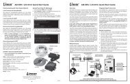
COMPONENT IDENTIFICATION<br />
WOOD<br />
BLOCK<br />
POWER HEAD/DRIVE<br />
RAIL ASSEMBLY<br />
MANUAL RELEASE<br />
TAG<br />
STEPLADDER<br />
BELL WIRE<br />
SPOOL<br />
(when supplied)<br />
DOOR<br />
BRACKET<br />
OPENER<br />
HARDWARE<br />
BAG<br />
TOOLS REQUIRED<br />
HACKSAW<br />
SOCKET WRENCH<br />
3/8” SOCKET<br />
7/16” SOCKET<br />
TAPE MEASURE<br />
OPTIONAL<br />
!<br />
Child can be pinned under automatic garage<br />
door. Death or serious injury can result.<br />
• Never let child walk or run under moving door.<br />
• Never let child use door opener controls.<br />
• Always keep moving door in sight.<br />
• If person is pinned, push control button or use<br />
emergency release.<br />
• Test door opener monthly:<br />
Refer to your owner’s manual<br />
Place one-inch object (or 2x4 laid flat) on floor.<br />
If door fails to reverse on contact, adjust opener.<br />
If opener still fails to reverse door, repair or replace opener.<br />
TRANSMITTER<br />
WARNING<br />
PUSHBUTTON<br />
“WARNING” LABEL<br />
WALL PUSHBUTTON<br />
HAMMER<br />
4<br />
SENSOR ‘U’<br />
BRACKET<br />
RED<br />
RELEASE<br />
KNOB<br />
WALL<br />
BRACKET<br />
DOOR ARM ROD<br />
110046<br />
DRILL<br />
DRILL & BITS<br />
SMALL SCREW DRIVER<br />
(1/8” HEAD)<br />
SCREW DRIVER<br />
SAFE FINISH HARDWARE<br />
LEVEL<br />
DOOR ARM<br />
TUBE SECTION<br />
SENSOR ‘L’<br />
BRACKET<br />
SAFE FINISH<br />
PHOTOSYSTEM<br />
SENSORS<br />
1/2” OPEN END<br />
WRENCH
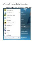
NOTE: The Rail/Chain Assembly is<br />
packaged separately from the Power<br />
Head Unit. The trolley, front idler/<br />
tension adjustment assembly, chain,<br />
drive gear and limit cams are assembled<br />
to the Rail/Chain Assembly at the<br />
factory. Follow the steps outlined<br />
below to complete assembly prior to<br />
installation. Refer to the component<br />
identification illustrations on the<br />
previous page.<br />
STEP 1: Prior to attaching the motor<br />
drive unit to the rail assembly, the Open<br />
Spring<br />
and Close adjustment bolts must be<br />
installed. Place the threaded end of the<br />
L-Shaped Adjustment Bolt<br />
adjustment bolt through the hole in the<br />
rail and then slip the head of the bolt<br />
through the center of the double key<br />
hole. Slide the spring over the bolt and attach load adjusting nut. Tighten until the tip of the bolt extends 3/16” outside the nut.<br />
Repeat above for the other side.<br />
STEP 2: Protect the Power Unit cover from scratching during assembly by placing it on cardboard. Loosen the two 5/16" lock<br />
washer nuts on top of the power head drive unit.<br />
STEP 3: VERY IMPORTANT ! Position a paper shim around the power head unit drive gear (standard weight paper, see<br />
illustration). Shim must remain in place while assembling the power head unit to the Rail/Chain assembly to ensure a proper gear<br />
mesh and avoid excessive long term wear.<br />
STEP 4: Align the four key holes in the Rail/Chain assembly with<br />
the two front guide tabs and the two rear bolt studs on the power<br />
head unit and place the rail/chain assembly in place over the power<br />
head unit. The power head drive unit limit lever protrudes up<br />
through the rail/chain assembly sensing plate. Take care not to bend<br />
the lever when<br />
assembling. Slide the<br />
power head drive unit<br />
forward until the gear<br />
meshes with the rail/<br />
chain assembly drive<br />
gear. Check to make<br />
sure the front guide tabs<br />
on the power head unit<br />
are securely locked on<br />
the rail/chain assembly.<br />
If Your Opener Is Supplied Fully Assembled, Please Disregard This Page.<br />
110047-2<br />
Take care not to<br />
bend limit lever<br />
Assembled and<br />
In Position<br />
Limit Lever<br />
STEP 5: The power head drive unit should be move forward until<br />
all play between the gears has been eliminated, but no additional force should be used that could cause pressure on the motor (power<br />
head unit) drive gear. Tighten the two 5/16" lock washer nuts on top of the power head drive unit that were loosened in Step 2 above.<br />
When the opener is first activated the paper shim will be ejected. The paper shim should have the profile of the gears to indicate the<br />
proper mesh between them.<br />
STEP 6: Recheck the nuts used to secure the Rail/Chain assembly to the Power Head Unit, making sure they are tight.<br />
Assembly is now complete and you are ready to begin installation of the opener.<br />
5<br />
A: ASSEMBLY INSTRUCTIONS<br />
5/16” Lock<br />
Washer Nuts<br />
Paper Shim<br />
Spring<br />
Force Adjusting<br />
Plastic-Insert<br />
Locking Nut<br />
Double Key Hole<br />
Limit<br />
Lever<br />
Front Guide<br />
Tabs (2)<br />
110047-1<br />
110047-3
B: IMPORTANT INSTALLATION INSTRUCTIONS<br />
IMPORTANT INSTALLATION INSTRUCTIONS<br />
WARNING<br />
TO REDUCE THE RISK OF SEVERE<br />
INJURY OR DEATH: READ AND FOLLOW<br />
ALL INSTALLATION INSTRUCTIONS!<br />
WARNING: AN UNBALANCED DOOR OR<br />
ONE THAT STICKS OR BINDS MAY<br />
PREVENT THE SENSING SYSTEM FROM<br />
WORKING PROPERLY, CAUSING INJURY OR<br />
DEATH. ENSURE DOOR IS PROPERLY<br />
BALANCED AND ELIMINATE ANY STICKING OR<br />
BINDING PRIOR TO INSTALLATION OF<br />
OPERATOR. A properly balanced door will open<br />
slowly from a 3/4 open position, close slowly from a<br />
3/4 closed position, and remain still at a 1/2 open<br />
position. If the door is not properly balanced, HAVE<br />
A QUALIFIED SERVICE PERSON MAKE<br />
REPAIRS TO CABLES, SPRING ASSEMBLIES<br />
AND OTHER DOOR HARDWARE BEFORE<br />
INSTALLING THE OPENER<br />
WARNING: YOUR GARAGE DOOR IS THE<br />
LARGEST MOVING OBJECT IN YOUR<br />
HOUSE, THE SPRINGS, PULLEYS, CABLES<br />
AND MOUNTING HARDWARE UTILIZED TO<br />
BALANCE ITS OPERATION ARE UNDER<br />
EXTREME TENSION AT ALL TIMES AND CAN<br />
CAUSE SERIOUS PERSONAL INJURY, EVEN<br />
DEATH, IF DISTURBED. DO NOT ATTEMPT<br />
ADJUSTMENT. CALL A QUALIFIED SERVICE<br />
PERSON TO MOVE, LOOSEN OR ADJUST<br />
DOOR SPRINGS OR HARDWARE.<br />
• REMOVE ALL ROPES AND REMOVE OR MAKE<br />
INOPERATIVE ALL LOCKS CONNECTED TO<br />
THE GARAGE DOOR BEFORE INSTALLING<br />
THE OPENER.<br />
• DO NOT WEAR RINGS, WATCHES OR LOOSE<br />
CLOTHING WHILE INSTALLING OR<br />
SERVICING GARAGE DOOR OPENERS.<br />
WEAR SAFETY GOGGLES OR OTHER<br />
PROTECTIVE EYEWEAR.<br />
• IF POSSIBLE, INSTALL THE DOOR OPENER<br />
7zFT OR MORE ABOVE THE FLOOR. MOUNT<br />
THE EMERGENCY RELEASE 6 FT ABOVE THE<br />
FLOOR.<br />
• REINFORCE LIGHTWEIGHT FIBERGLASS,<br />
6<br />
ALUMINUM AND STEEL DOOR TOP SECTIONS<br />
TO AVOID DAMAGE AND TO INSURE PROPER<br />
OPERATION OF THE SAFETY REVERSE<br />
SYSTEM. CONTACT YOUR DOOR<br />
MANUFACTURER FOR A REINFORCEMENT<br />
KIT.<br />
• DO NOT CONNECT THE OPENER TO A<br />
POWER SOURCE UNTIL INSTRUCTED TO DO<br />
SO.<br />
• CHECK LOCAL BUILDING AND ELECTRICAL<br />
CODES FOR MANDATORY INSTALLATION<br />
AND WIRING REQUIREMENTS.<br />
• CONNECT POWER CORD ONLY TO A<br />
PROPERLY GROUNDED OUTLET. IF<br />
PERMANENT WIRING IS REQUIRED BY<br />
CODES, DISCONNECT POWER AT FUSE BOX<br />
OR CIRCUIT BREAKER BEFORE ATTEMPTING<br />
ANY WIRING CONNECTIONS.<br />
• LOCATE THE CONTROL PUSH BUTTON:<br />
A. WITHIN SIGHT OF THE DOOR, AND,<br />
B. AT A MINIMUM HEIGHT OF 5 FT SO SMALL<br />
CHILDREN CAN'T REACH IT, AND,<br />
C. AWAY FROM MOVING PARTS OF THE<br />
DOOR.<br />
• INSTALL THE ENTRAPMENT WARNING LABEL<br />
NEXT TO THE CONTROL PUSH BUTTON IN A<br />
PROMINENT LOCATION. INSTALL THE<br />
EMERGENCY RELEASE INSTRUCTION CARD,<br />
ATTACHING IT ON OR NEXT TO THE<br />
EMERGENCY RELEASE.<br />
• ADJUST THE SENSITIVITY ADJUSTMENTS<br />
ENOUGH TO ALLOW THE DOOR TO<br />
OPERATE, BUT NOT SO FIRMLY AS TO<br />
EXERT EXCESSIVE PRESSURE ON AN<br />
OBSTRUCTION BEFORE REVERSING.<br />
• AFTER INSTALLING THE OPENER, THE DOOR<br />
SHOULD REVERSE WHEN IT CONTACTS A<br />
1-1/2" HIGH OBJECT (A PIECE OF STANDARD<br />
2 X 4 BOARD LAID FLAT) ON THE FLOOR.
104367<br />
WARNING<br />
WARNING<br />
C: INSTALLING THE OPERATOR<br />
IMPORTANT!<br />
IDENTIFY YOUR DOOR TYPE FROM THOSE ILLUSTRATED BELOW AND FOLLOW<br />
INSTRUCTIONS FOR THAT TYPE OF DOOR<br />
SECTIONAL DOOR<br />
CURVED TRACK<br />
HIGH ARC OF<br />
DOOR TRAVEL<br />
TRACK<br />
DOOR DOOR<br />
ONE PIECE DOOR<br />
HORIZONTAL TRACK<br />
JAMB HARDWARE<br />
HIGH ARC OF<br />
DOOR TRAVEL<br />
TRACK<br />
FOR THESE TYPES OF DOORS USE 1/3 HP<br />
MODEL AC9300 OR 1/2 HP MODEL AC9500.<br />
USE 7 FT, 8 FT OR 10 FT RAIL ASSEMBLY<br />
(MATCH DOOR HEIGHT)<br />
REINFORCE THE HEADER WALL<br />
Reinforce the header wall (wall above the door opening as required,<br />
to ensure rigid mounting of the front wall bracket.<br />
Locate the vertical centerline of your garage door and mark it on the<br />
header above the door and on the top rail of the door.<br />
104369<br />
HORIZONTAL<br />
LINE<br />
SPRINGS, PULLEYS, CABLES AND MOUNTING HARDWARE USED TO BALANCE YOUR<br />
GARAGE DOOR ARE UNDER EXTREME TENSION AT ALL TIMES AND CAN CAUSE SEVERE<br />
INJURY OR DEATH IF DISTURBED. DO NOT ATTEMPT ADJUSTMENT.<br />
VERTICAL<br />
CENTERLINE<br />
7<br />
ONE PIECE DOOR<br />
NO TRACK<br />
JAMB HARDWARE<br />
DOOR<br />
JAMB<br />
HARD-<br />
WARE<br />
110048<br />
HIGH ARC OF<br />
DOOR TRAVEL<br />
ONE PIECE DOOR<br />
NO TRACK<br />
PIVOT HARDWARE<br />
HIGH ARC OF<br />
DOOR TRAVEL<br />
DOOR<br />
FOR THESE TYPES OF DOORS USE<br />
1/2 HP MODEL ACJ9500.<br />
USE 7J RAIL<br />
(FOR DOOR HEIGHT UP TO 8 FT)<br />
PIVOT<br />
104368<br />
Reinforce with 2” x 6”<br />
as required to insure<br />
rigid mounting.<br />
Vertical Center<br />
Line<br />
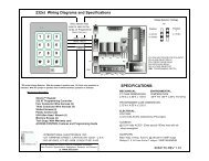
STEP 1: Mounting the Front Bracket — Sectional Doors and One-<br />
Piece Doors with Track (For One-Piece Doors without track see Step 1A,<br />
next): Mark a vertical centerline on the header above the door. By<br />
manually raising the door, determine the high arc of the door’s travel (see<br />
illustration, top of previous page) and using a level, transfer this<br />
measurement to the header (see illustration at left). Draw a horizontal line,<br />
crossing the previously drawn centerline, at this point. Install the Front<br />
Mounting Bracket securely wit lag screws as shown below. If necessary,<br />
reinforce the header with steel angle iron or wood to ensure a secure<br />
mount.
C: INSTALLING THE OPERATOR<br />
WARNING<br />
WARNING<br />
Door<br />
10437<br />
FRONT MOUNTING BRACKET MUST BE INSTALLED TO A STRUCTURAL SUPPORT<br />
(STUD) ON THE HEADER WALL. FAILURE TO DO SO COULD CAUSE SENSING<br />
SYSTEM TO MALFUNCTION, RESULTING IN ENTRAPMENT, INJURY OR DEATH.<br />
REINFORCE HEADER USING 2 x 6 WOOD STUDS AND LAG SCREW OR ANGLE<br />
IRON AND LAG SCREWS AS NECESSARY (NOT PROVIDED).<br />
Header Bracket<br />
Bracket Distance Above Floor<br />
(See Chart)<br />
HIGH ARC RISE HIGH ARC RISE<br />
HORIZONTAL LINE<br />
4 INCHES 8 INCHES<br />
4 TO 8 INCHES 13 INCHES<br />
8 TO 12 INCHES 18 INCHES<br />
Highest Point<br />
of Travel<br />
Measure<br />
Distance<br />
to Floor<br />
Garage<br />
Floor<br />
8<br />
STEP 1A: Mounting the Front Bracket — One<br />
Piece Doors Without Track: Mark a vertical<br />
centerline on the header above the door. Manually raise<br />
the door to its high arc position and temporarily clamp<br />
in that position. With the door in this high arc position,<br />
measure the distance from the top of the door to the<br />
floor (see figure at left). Subtract the actual door height<br />
from the high arc distance to the floor. This is the high<br />
arc rise of the door. Unclamp and close the door.<br />
Using the table below, draw a horizontal line at the<br />
appropriate height above the door to intersect with the<br />
vertical centerline.<br />
1/2” Above<br />
High Arc Mark<br />
High Arc Mark<br />
Center of<br />
Door<br />
110049<br />
Front Wall<br />
Bracket<br />
Mount the Front Mounting Bracket securely with lag<br />
screws as shown in figure above. If necessary,<br />
reinforce the header with steel angle iron or wood to<br />
ensure a secure mount.<br />
STEP 2: Raise the front of the Rail/Chain assembly so that the Front Rail Bracket and Wall Mounting Bracket align. Insert the<br />
1/4” x 4” bolt and tighten nut loosely for now. Later in the installation, this nut must be tightened securely.<br />
STEP 3 — Sectional Doors and One Piece Doors with Track: Raise the Opener and rest the Power Unit on a ladder or other<br />
sturdy support. Open the door the full open position.<br />
Allow 2" of space between the Tee Rail and the top<br />
section of the door (as shown in the illustration on page<br />
9).<br />
STEP 3A — One Piece Doors without Track: Raise<br />
the opener and rest the power unit on a ladder or other<br />
sturdy support. Open the door to the high arc position.<br />
Allow 2” of space between the tee rail and the door (at the<br />
high arc position) as shown in the illustration on page 9.<br />
The opener will be angled as shown. This is necessary for<br />
proper operation.<br />
NOTE: Since the Opener will be secured permanently<br />
in this position, open and close the door a few times to be<br />
sure the door does not rub on the Tee Rail and that you<br />
have allowed the proper clearances before proceeding.<br />
Wall<br />
Mounting<br />
Bracket<br />
1/4” x 4”<br />
Hex Head Bolt<br />
Wall Mounting Bracket<br />
Nut<br />
Cardboard or Cloth to<br />
protect the Housing<br />
110050-1
C: INSTALLING THE OPERATOR<br />
STEP 4: Mount Power Head to Ceiling: Since there is such variety in ceiling structures, all the mounting possibilities for the Power<br />
Unit cannot be illustrated here. The main concern is mounting the Power Unit securely to the ceiling joists for operational strength,<br />
rigidity and safety. Although there are a series of mounting slots provided on the power unit, try to secure the mounting straps in<br />
the slots closest to the front. Mounting<br />
may usually be accomplished using<br />
standard 1-1/4“ perforated steel angle<br />
available at most hardware stores. If in<br />
doubt about location of, and attachment to,<br />
ceiling joists, a carpenter should be<br />
contacted to provide assistance. A cross<br />
brace will be necessary if power head is<br />
mounted 8” or more from the ceiling.<br />
STEP 5: Return to the Rail/Wall<br />
Mounting Bracket and securely tighten<br />
the bolt and nut that connect the Rail Front<br />
Idler bracket and the Wall Mounting<br />
Bracket. Take care not to over tighten the<br />
nut; tighten only until the end of the bolt is<br />
(See Step 2).<br />
Mounting The Power Head End of<br />
Opener<br />
STEP 6: Align the center of opener tracks<br />
with the center line previously marked on the<br />
top section of the garage door to ensure rail<br />
will be parallel with the direction of door<br />
travel.<br />
Use supplied hangers from the ceiling beams<br />
to hang the opener at the power head end (be<br />
sure to locate and mount to the solid structural<br />
beams, as illustrated). Predrill with 3/16” drill<br />
bit and use supplied 1/4” x 1-1/2” lag screws<br />
to ensure a rigid mount.<br />
SECTIONAL DOORS AND ONE-<br />
PIECE DOORS WITH TRACKS<br />
ALLOW 2” BETWEEN<br />
TOP OF DOOR AND RAIL<br />
DOOR FULLY<br />
OPEN<br />
NOTE: Hanging brackets should be at an<br />
angle to provide rigid support. If hangers have no angle or if you use longer hangers, cross brace the<br />
hangers to eliminate the possibility of sway during operation of the opener.<br />
WARNING<br />
Structural<br />
Beams<br />
Opener<br />
Power Head<br />
Fiberglass, aluminum or lightweight steel garage<br />
doors will require reinforcement before installation of<br />
the door mounting bracket Contact your door<br />
manufacturer for a reinforcement kit or instructions.<br />
STEP 7: Door Bracket Installation<br />
NOTE: If the door is of light construction it may be necessary to reinforce the<br />
center stile with steel angle or wood to prevent damage to the door if it<br />
encounters an obstruction on closing.<br />
Mount the door bracket using two 1/4”-20 x 2” carriage bolts and 1/4” nuts<br />
(supplied), on center line of door with the middle hole in line with the top<br />
rollers.<br />
If your door comes equipped with a strut<br />
mounted opener bracket, proceed to Step 8.<br />
110051-1<br />
9<br />
110050-2<br />
Cut and bend<br />
Hangers to fit<br />
ONE PIECE DOORS<br />
WITHOUT TRACKS<br />
TOP OF<br />
DOOR IN<br />
HIGH ARC<br />
POSITION<br />
ALLOW 2” BETWEEN<br />
HIGH ARC<br />
104373<br />
For finished ceilings, or if<br />
structural beams are out of<br />
position for mounting use a<br />
third mounting angle (not<br />
included) making sure it is<br />
securely mounted to beams.<br />
Door Center Line<br />
Top Roller<br />
Guideline<br />
Top Roller<br />
Guideline<br />
Reinforce Door<br />
Vertically and<br />
Horizontally<br />
Mounting<br />
Bracket<br />
110051-2
C: INSTALLING THE OPERATOR<br />
Step 8: Connecting Door Arm to Trolley<br />
(THIS IS FOR SECTIONAL DOORS ONLY - FOR ONE<br />
PIECE DOORS PROCEED TO STEP 10)<br />
The door arm assembly consists of the door arm tube section and door arm<br />
rod which are packaged separately. To assemble, screw the door arm rod into<br />
the the door arm tube in a clockwise direction approximately ten turns.<br />
Connect the door arm assembly into the trolley with the open end of the rod<br />
hook facing the power head unit (away from the door). Extend the manual<br />
release cord (connected to the trolley) and thread through the warning tag and<br />
red pull knob handle. Adjust so the knob is 6 feet above the floor and secure<br />
with a double overhand knot in the end of the release cord.<br />
Release the trolley (leave door arm attached) with the manual release cord<br />
and pull trolley toward the door.<br />
110054-2<br />
Type 2: Strut Mounted Bracket<br />
Visually align the door arm connecting hole with the connecting<br />
pin of the strut by rotating the tube section in the appropriate<br />
direction.<br />
Release the trolley (leave door arm attached) with the manual<br />
release cord and pull trolley toward the power head unit. Now<br />
rotate the door arm tube section two turns counterclockwise<br />
(increasing the exposed length of the door rod) to provide a cushion<br />
when the door is closed or encounters an obstruction. Align<br />
connecting hole in the door arm with the strut mounted connecting<br />
bracket. Insert connecting pin through the hole in the door arm.<br />
Secure the connecting pin to the strut bracket according to the<br />
manufacturer’s instructions.<br />
Note: Door Bracket Mount or Strut Mount - If rod<br />
bottoms in cushion tube, cut rod to allow for proper<br />
function of this assembly.<br />
10<br />
Cushion<br />
Arm<br />
Assembly<br />
Trolley<br />
(Close Limit Position)<br />
Step 9: Connecting the Door Arm to the Door<br />
110053-2<br />
Type 1: Door Mounted Bracket<br />
Visually align the door arm connecting hole with the middle hole of<br />
the door bracket by rotating the tube section in the appropriate<br />
direction.<br />
Release the trolley (leave door arm attached) with the manual release<br />
cord and pull trolley toward the power head unit. Now rotate the door<br />
arm tube section two turns counterclockwise (increasing the exposed<br />
length of the door rod) to provide a cushion when the door is closed or<br />
encounters an obstruction. Align connecting hole in the door arm to<br />
middle hole in the door bracket; insert 3/8” diameter bolt and tighten<br />
locking nut, allowing for free pivot of the arm. Note: Do not<br />
overtighten locking nut as this will cause binding between the door<br />
arm and door bracket.<br />
Alternate Strut<br />
Connecting Bracket<br />
Cut to Fit<br />
110054-2
Step 10: Connecting the Door Arm to the Door - ONE PIECE<br />
DOORS (USING OPTIONAL ONE PIECE DOOR ARM ASSEMBLY)<br />
Attach door arm brackets to the top surface of the door on the center line.<br />
Reposition Open and Close limit stops so trolley stops in locations as shown.<br />
Assemble the door arm by screwing curved rod into straight tube section. Allow<br />
approximately 6” of rod to project outside of the straight tube.<br />
Release trolley with red knob handle and move to a convenient position between<br />
Step 12: Install a Rough Service lamp bulb (75 Watt maximum) firmly<br />
in the light socket. Light bulbs in Door Openers are subject to vibration<br />
during normal operation which may shorten their life spans. Rough<br />
Service bulbs, available at most hardware stores, are recommended. Fit<br />
Light Diffuser tabs into the panel tabs as shown.<br />
C: INSTALLING THE OPERATOR<br />
STEP 11: Connecting The Electrical Power Consult the label on the rear panel of the Opener to determine its proper<br />
working voltage. Normally it will be marked for 115V, 60 cycle operation. (If it is an export model designed for 220V, 50 cycle<br />
operation, the label will clearly indicate this.) The Opener must be plugged into a properly grounded receptacle within 3 FT of the<br />
Power Unit. A GFI Type receptacle is recommended. Do not use 2-prong adapters and do not use extension cords for anything<br />
more than temporary hook-up and testing purposes. Receptacle wiring should be No. 14 or heavier, and must be in compliance with<br />
local building and electrical codes.<br />
110053-1<br />
Closed Limit<br />
Stop Location<br />
Door Arm<br />
Closed Door<br />
Normal<br />
Connection<br />
Fully Closed<br />
Trolley<br />
Open Door<br />
Open Limit<br />
Stop Location<br />
Door Arm<br />
Connection<br />
Door Arm Bracket<br />
Permanent Wiring Connection<br />
Using the two wires (black & white) that were left when you<br />
cut off the line cord, splice in the permanent connections.<br />
Ground Wire<br />
Door Arm<br />
11<br />
Fully Open<br />
110055-1<br />
Door<br />
Brackets<br />
Bolt/Nut<br />
Straight Tube<br />
Open and Close limits. Connect curved rod<br />
section to trolley.<br />
Slide door arm and trolley toward door; connect<br />
the tube assembly to the door bracket with the<br />
3/8” diameter bolt and locking nut, tightening<br />
enough to allow for door arm pivot. Do not<br />
overtighten the locking nut.<br />
Press door control button and run opener through<br />
full open and close cycles, adjusting the limit<br />
stops as required to fully open and close the<br />
door. At full closed position, the door arm<br />
assembly should compress approximately one<br />
inch.<br />
WARNING<br />
If local codes require permanent wiring, a GFI type circuit<br />
breaker is recommended to protect the line. Remove the Strain<br />
Relief Bushing and withdraw the Line Cord from the rear of the<br />
Power Unit to expose the three insulated connectors. Cut the<br />
wire at the rubber jacket of the Line Cord and wire in<br />
permanently, employing proper wiring practices. Discard Strain<br />
Relief. It is not used with permanent wiring.<br />
6”<br />
Clips<br />
110054-2<br />
IMPROPER WIRING COULD CAUSE<br />
ELECTROCUTION OR DAMAGE TO<br />
CIRCUITRY. FOLLOW LOCAL BUILDING<br />
AND ELECTRICAL CODES.<br />
110051-3
D: CONTROL AND AUXILIARY EQUIPMENT<br />
INSTALLATION OF A STANDARD WALL PUSH BUTTON OR DELUXE WALL STATION CONTROL<br />
A standard wall push button is included<br />
in your hardware package, an optional<br />
Deluxe Wall Station may be purchased<br />
from your installing dealer. The operating<br />
parameters for the standard wall<br />
push button and the Deluxe Wall Station<br />
are outlined on pages that follow<br />
(“Operating Instructions”) to see what<br />
mode of operation is right for you. Allstar<br />
recommends the Deluxe Wall Station<br />
installation, as it will provide full<br />
WARNING<br />
WARNING<br />
control over the garage door operator and its functions at all times. You may install one Deluxe Wall Station and one or more standard<br />
push buttons to a Challenger <strong>AC9000</strong> Series operator following the cautions and instructions outlined below.<br />
STEP 1: After determining a suitable location, usually near the access door and at least 5 feet above the floor to prevent use by<br />
children, use the standard wall push button or Deluxe Wall Station as a guide to mark the mounting holes. Drill holes for drywall<br />
anchors or screws. NOTE: Do not mount directly to masonry walls. Use backer board.<br />
STEP 2: A length of 2-conductor, #22 gauge wire (or heavier) is required to connect the control button to the garage door operator.<br />
Strip approximately 2” of the wire jacket from one end and 1/2” of insulation from each wire. Carefully connect one wire to each of<br />
the two terminals. Carefully tuck the loose wires into the case and mount the unit using appropriate screws.<br />
STEP 3: Run the wire from the control button to the operator, supporting it at 18” intervals with suitable staples. Leave a<br />
sufficient length to make the necessary connections to the operator terminal strip.<br />
WARNING: SOME LOCAL BUILDING CODES DO NOT ALLOW<br />
SURFACE WIRING. BE SAFE AND CHECK WITH YOUR LOCAL<br />
BUILDING INSPECTOR FIRST.<br />
STEP 4: Ensure power is OFF to the operator or disconnect the power from the<br />
operator. Strip approximately 4” of jacket from the end of the wire and 1/2”<br />
insulation from each wire. Connect to terminals 0 and 1 as shown in the<br />
illustration. Support the wire near the operator with wire ties.<br />
Step 5: Install the<br />
Control Button<br />
Warning Label<br />
109986<br />
WARNING<br />
WARNING<br />
supplied with your<br />
Challenger <strong>AC9000</strong><br />
Series operator near<br />
the control button<br />
(see illustration).<br />
Repeat the Steps 1<br />
thru 5 above to install<br />
additional standard<br />
wall push buttons<br />
if desired.<br />
Every control must<br />
have a separate Control<br />
Button Warning<br />
Label mounted near it. Contact the factory for additional labels if<br />
needed.<br />
12<br />
A CHILD OPERATING THE DOOR CONTROLS<br />
RISKS INJURY — OR DEATH — TO HIMSELF AND<br />
OTHERS. DO NOT ALLOW CHILDREN TO<br />
OPERATE ANY DOOR CONTROLS.<br />
MOUNT THE PUSHBUTTON AT LEAST 5 FT FROM<br />
THE FLOOR, OUT OF REACH OF CHILDREN.<br />
!<br />
WARNING<br />
Child can be pinned under automatic garage<br />
door. Death or serious injury can result.<br />
• Never let child walk or run under moving door.<br />
• Never let child use door opener controls.<br />
• Always keep moving door in sight.<br />
• If person is pinned, push control button or use<br />
emergency release.<br />
• Test door opener monthly:<br />
Refer to your owner’s manual<br />
Place one-inch object (or 2x4 laid flat) on floor.<br />
If door fails to reverse on contact, adjust opener.<br />
If opener still fails to reverse door, repair or replace opener.<br />
104350<br />
CONTROL BUTTON WARNING LABEL<br />
IMPROPER DOOR OPERATION COULD<br />
CAUSE INJURY OR DEATH. WARNING<br />
LABEL MUST BE MOUNTED ON WALL NEAR<br />
THE PUSHBUTTON. ALL WARNINGS AND<br />
INSTRUCTIONS ON THE LABEL SHOULD BE<br />
STRICTLY ADHERED TO.
SAFE FINISH PHOTOSYSTEM INSTALLATION<br />
D: CONTROL AND AUXILIARY EQUIIPMENT<br />
Identify which side of the garage door opening (if any) the sun is “likely” to shine<br />
into. As sunlight may cause undesirable operation, mount the sending unit (black<br />
button below the window) on the side of the door opening exposed most to the sun.<br />
STEP 1: Mounting the Photosystem Wall Brackets Select a<br />
mounting position 5 inches above the floor to the center line wall bracket. The<br />
sending and receiving units should be mounted inside the door opening to minimize<br />
any interference by the sun. However, the sensors should be mounted as close to<br />
the door track or inside edge of the door as possible to offer maximum entrapment<br />
104382<br />
STEP 2: Wire Connect the Photosystem<br />
protection. The brackets may be temporarily<br />
mounted to the wall (or jamb) with the 1” flathead<br />
nail provided. Leave this nail in place after<br />
installation of the lag screw below to prevent<br />
accidental rotation of the bracket NOTE: It is very important that the wall brackets be mounted at<br />
exactly the same height so they will be aligned.<br />
Using the 1/4” x 1-1/2” lag screw provided, attach the wall bracket securely to the wall. In some<br />
installations it may be necessary to attach wooden spacers to the wall to achieve the required<br />
clearance. Expansion bolts (not supplied) may be required to attach brackets to walls constructed of<br />
materials other than wood or gypsum. Repeat for the wall bracket on the other side of the door<br />
opening.<br />
Refer to page 20 for wiring diagrams of the Safe Finish Photosystem and garage door opener. The following outlines the<br />
“PHOTOCELL <strong>SERIES</strong> CONNECTION (RECEIVER FIRST)” wiring diagram.<br />
A. Run a wire pair (not supplied) around the garage door jamb between the transmitter and receiver "L" mounting brackets.<br />
NOTE: Leave about 12” of extra wire at each end. Use a minimum 22 gauge solid "trace" wire (one wire in set should be<br />
marked to identify it at each end) for interconnect.<br />
B. Run a wire pair (20 or 22 gage solid wire) from the receiver position (unit with "LED" light in the front, may be either side of<br />
the door) back to the rear bulkhead of the garage door opener. NOTE: Leave about 12” of extra wire at the receiver end and<br />
about 24” of extra wire at the opener end. Use a minimum 22 gauge solid "trace" wire (one wire in set should be marked to<br />
identify it at each end) for interconnect.<br />
C. Strip approximately 5/16” from each wire end at the photosystem units and at the opener.<br />
D. Using two (2) wire nuts (supplied), connect the wire ends at the Safe Finish Photosystem transmitter to the pigtail wire ends<br />
coming out of the transmitter unit. Observe polarity, connect the trace wire ends (with black stripe) together and the<br />
unmarked wire ends together. See wiring diagrams on page 20 .<br />
Using two (2) wire nuts (supplied), connect the wire ends at the SAFE FINISH Photosystem receiver to the pigtail wire ends<br />
coming out of the receiver unit. Observe polarity, connect the trace wire ends (with black stripe) together and the<br />
unmarked wire ends together.<br />
STEP 3: Final Installation of Photosystem Units<br />
A. Attach the"U" brackets to the "L" brackets with a 1/4-20 carriage bolt,<br />
washer and hex nut (provided). Insert the bolt from the inside of the<br />
"U" bracket and hand tighten only at this time.<br />
B. Place the transmitter and receiver units into their respective "U"<br />
brackets. NOTE: It is easier to slip the photosystem units in from the<br />
side of the bracket than forcing them in from the front of the bracket.<br />
See Illustration, at right.<br />
C. Connect the interconnect wire pair to the garage door opener terminals.<br />
Connect the trace wire (with black stripe) to the operator<br />
terminal marked “4” and the solid color wire to the operator<br />
terminal marked “5”. See Wiring Diagrams on page 20 .<br />
13<br />
5 Inches<br />
Above the Floor<br />
12 Inches From Door Opening<br />
#8 Hex<br />
Head<br />
Screw<br />
110052-1<br />
1/4” x 1-1/2”<br />
Lag Screw<br />
104383
D: CONTROL AND AUXILIARY EQUIPMENT<br />
INSTALLATION OF RADIO CONTROLS:<br />
The following instructions detail installation of Model 9931 Radio Controls. For other Radio models, see instructions<br />
packaged with product.<br />
TRANSMITTER:<br />
To gain access to<br />
the Transmitter<br />
Coding Switches,<br />
remove the Battery<br />
Cover from the<br />
front of the<br />
Transmitter by<br />
sliding it toward the<br />
bottom of the<br />
Transmitter as<br />
illustrated.<br />
Setting The Coding Switches: When setting the Coding Switches THE FACTORY<br />
PRE-SET CODES MUST BE CHANGED TO PREVENT UNAUTHORIZED<br />
OPERATION. Transmitter and Receiver codes must be set IDENTICALLY. If just<br />
one Code Switch is mismatched, the Radio Controls will not function.<br />
NOTE: For security reasons, it is advisable NOT to set all the switches in the<br />
same position.<br />
Mounting The Receiver: After setting the Coding Switches, mount the Receiver on<br />
the rear panel of the Opener by connecting it to Terminals 1, 2 and 3. For proper<br />
operation, the Antenna Wire should be POINTED STRAIGHT DOWN toward the<br />
floor.<br />
POINT ANTENNA<br />
STRAIGHT DOWN 108386<br />
After installing the Radio<br />
Controls, check their operation<br />
by moving approximately 35<br />
FT away from the garage door<br />
and pressing the Transmitter<br />
Button. Operation at this<br />
distance should be reliable.<br />
If the Transmitter doesn't<br />
activate door operation, check<br />
that all Coding Switches are set<br />
identically. If the operational<br />
distance is inadequate, try<br />
moving the position of the<br />
Transmitter in the car. If the distance is still inadequate, try bending the Antenna Wire<br />
to a different angle. If the distance is still<br />
inadequate, replace the Battery with a standard 9-<br />
Volt “transistor radio” Battery (NEED 1604). The<br />
Battery is located in the front compartment next to<br />
the Coding Switches.<br />
The Transmitter may be hand held if desired by<br />
removing the Visor Clip from the rear of the Case<br />
as illustrated. Place your finger in the loop at the<br />
top of the visor, and your thumb on the top edge<br />
of the Transmitter. Push down with your thumb<br />
and pull up with your finger. The clip will release<br />
and pull out easily.<br />
104384<br />
14<br />
RECEIVER: The<br />
Receiver Coding<br />
Switches can be<br />
accessed by<br />
removing the small<br />
door from the back<br />
of the<br />
Receiver using a<br />
small screwdriver or<br />
knife.<br />
104388<br />
104385<br />
104386<br />
CODING BLOCK: Transmitter and<br />
Receiver Coding Switches are contained<br />
in identical Coding Blocks, consisting of<br />
nine small switches, labeled 1 - 9, each<br />
of which can be set in any of three<br />
positions, labeled +, 0, -<br />
WARNING<br />
WARNING<br />
TO PREVENT THE RISK<br />
OF PERSONAL INJURY,<br />
DAMAGE TO DOOR OR<br />
PROPERTY, ONLY<br />
OPERATE DOOR<br />
CONTROLS WHEN DOOR<br />
IS IN CLEAR VIEW. KEEP<br />
REMOTE CONTROL<br />
AWAY FROM CHILDREN<br />
IN SECURE AREA.
WARNING<br />
E: OPERATION AND ADJUSTMENT INSTRUCTIONS<br />
IMPORTANT SAFETY INSTRUCTIONS<br />
TO REDUCE THE RISK OF SEVERE<br />
INJURY OR DEATH: READ AND FOLLOW<br />
ALL USER / SAFETY INSTRUCTIONS!<br />
• NEVER let children operate or play with door controls. Keep the Remote Control away from<br />
children.<br />
• ALWAYS keep a moving door in sight and keep people and objects away from the door area<br />
until the door is completely closed. NO ONE SHOULD CROSS THE PATH OF A MOVING<br />
DOOR.<br />
• NEVER GO UNDER A STOPPED, PARTIALLY OPEN DOOR.<br />
• TEST THE DOOR OPENER MONTHLY. The door MUST reverse upon contact with a 1-1/2”<br />
high object (or a 2 X 4 board laid flat) on the floor. After adjusting the sensitivity or the limit<br />
of travel, ALWAYS RETEST the Opener. Failure to ADJUST THE OPENER PROPERLY may<br />
result in SERIOUS INJURY OR DEATH.<br />
• If possible, USE THE EMERGENCY RELEASE only when the door is closed. Use caution<br />
when using the Release with the door open. WEAK OR BROKEN SPRINGS MAY ALLOW<br />
THE DOOR TO CLOSE RAPIDLY, CAUSING SEVERE INJURY OR DEATH.<br />
• KEEP THE GARAGE DOOR PROPERLY BALANCED. See the door owner's manual. An<br />
improperly balanced door MAY CAUSE SEVERE INJURY OR DEATH. Have a QUALIFIED<br />
SERVICE PERSON MAKE REPAIRS TO CABLES, SPRING ASSEMBLIES AND OTHER<br />
HARDWARE.<br />
• SAVE THIS INSTRUCTION MANUAL.<br />
TURNING ON POWER TO THE OPERATOR<br />
NOTE: It is now necessary to turn on the power in order to run the Opener to test the operation and check the<br />
limit settings. Before doing so, ensure that all mounting hardware is installed and has been properly tightened,<br />
that all electrical connections are per local code requirements, and that proper wiring practices have been<br />
followed. Also, double-check that all ropes have been removed from the door and that the doorway is clear.<br />
BASIC OPERATING PARAMETERS<br />
Please note the following Operating Parameters which apply to Openers with Auxiliary Entrapment Protection System (Safe Finish<br />
Photosystem, Installation Instructions on Page 13) and a standard wall push button connected. Please see page 17 for instructions<br />
concerning the Deluxe Wall Push Button operating parameters.<br />
HOW TO ACTIVATE THE OPENER<br />
Never let children operate or play with the door controls. Keep Remote Control Away for Children.<br />
Use any of the following devices:<br />
1. The Remote Control Transmitter. Hold the push button down until the door starts to move, then release button.<br />
2. The Door Control Button. Momentary push of the button until the door starts to move. Constant push of the button until the<br />
door is closed is required if light flashes.<br />
3. An Outside Keylock or Keyless Entry System (if you have installed either of these options, see Mfg’s instructions).<br />
15
E: OPERATION AND ADJUSTMENT INSTRUCTIONS<br />
HOW THE DOOR MOVES WHEN THE OPENER IS ACTIVATED<br />
Always keep moving door in sight and away from people and objects until it is completely closed<br />
NO ONE SHOULD CROSS THE PATH OF A MOVING DOOR.<br />
IF THE DOOR IS...<br />
...FULLY OPEN, then pushing the standard wall Push Button or the radio control will cause the door to begin MOVING<br />
DOWNWARD.<br />
...FULLY CLOSED, then pushing the wall Push Button or the radio control will cause the door to begin MOVING UPWARD.<br />
...MOVING UPWARD, then pushing the wall Push Button will cause the door to STOP. The next push of the wall button will<br />
cause the door to begin MOVING DOWNWARD (Alternate Action Operation).<br />
...MOVING DOWNWARD, then pushing the wall Push Button or the radio control will cause the door to STOP. The next<br />
activation will cause the door to BEGIN MOVING UPWARD.<br />
...MOVING DOWNWARD and an obstruction is encountered, the door will STOP, PAUSE AND REVERSE TO THE OPEN<br />
DIRECTION.<br />
...MOVING UPWARD and an obstruction is encountered, the door will STOP. The next activation will CLOSE the door.<br />
The SAFE FINISH PHOTOELECTRIC uses an invisible beam which, when broken by an obstruction, causes a closing door to open<br />
and prevents an open door from closing.<br />
HOW THE LIGHT WORKS AND WHAT IT MEANS WHEN IT FLASHES<br />
1. The convenience light automatically turns on when the opener is activated and remains on for 4-1/2 minutes for your convenience<br />
and safety.<br />
2. The light will flash after coming upon an obstruction in the down direction to alert you of a problem. It will continue to flash for<br />
4-1/2 minutes, then shut off.<br />
3. Optional Wall Station adds the convenience of allowing the light to be turned on and stay on until turned off by a second push of<br />
the button or activation of door cycle.<br />
If the light begins to flash and the door does not move in the close direction from a push button or radio, the<br />
external safety device (Safe Finish Photoelectric) is activated or defective (misaligned or blocked etc.). To<br />
temporarily override and close door, activate pushbutton or wall station for 2 seconds; opener will begin moving<br />
in the down direction. The button must remain depressed until the cycle is completed. If the button is released<br />
before cycle is completed, the door will reverse and come to a fully open position. Problems with the safety system<br />
should be inspected by a professional garage door installer.<br />
HOW TO OPERATE THE DOOR MANUALLY - MANUAL RELEASE DISCONNECT<br />
The door should be fully closed, if possible, before using the manual disconnect. Weak or broken springs<br />
could allow an open door to fall rapidly. Property damage or serious personal injury could result. Do not<br />
use the manual release handle to pull the door open or closed.<br />
Your opener is equipped with a manual release recessed trolley-type disconnect<br />
system, enabling manual operation of the garage door during a power failure.<br />
The trolley is disconnected from the chain by pulling down on the red release<br />
handle, allowing the garage door to be operated manually.<br />
The trolley will automatically reconnect when power is restored and the door is<br />
activated.<br />
If the manual release is used, close the door before reactivating the opener.<br />
NOTE: Outside keylock manual releases are an available accessory and are recommended for garages without a service<br />
entrance.<br />
16<br />
Manual Release Knob<br />
Trolley<br />
110058-1
Adjustment #1: Opening Travel<br />
E: OPERATION AND ADJUSTMENT INSTRUCTIONS<br />
OPTIONAL THREE FUNCTION DELUXE WALL STATION<br />
When the Wall Station is connected to the operator per instructions supplied with the wall station, it will provide the following<br />
features:<br />
1. “OFF-ON” will prevent inadvertent operation of the door from any other push button, radio or keyless entry device. It will also<br />
as additional protection from unwanted operation during absence of the owner. This feature is to be activated only when the door is<br />
at the full open or close position and never while the door is moving.<br />
2. “LIGHT” button allows the convenience light to be turned on and stay on until turned off by a second push of the button or<br />
activation of the door cycle.<br />
3. “UP/DOWN” button provides normal opening and closing of the door by momentary activation of this push button. Function of<br />
door cycle is described above - “How the Door Moves When the Opener is Activated”.<br />
DO NOT USE ADJUSTMENTS TO COMPENSATE FOR A POORLY WORKING DOOR. THIS WILL<br />
INTERFERE WITH THE PROPER OPERATION OF THE REVERSING MECHANISM AND MAY<br />
DAMAGE THE DOOR.<br />
Your opener is assembled at the factory with the trolley in the forward position with the<br />
open limit stops snapped in place on the chain, set for a standard door.<br />
If you door is non-standard, move BOTH open limit stops, located just behind the trolley.<br />
As an example: For a 6 FT, 6 INCH door, move both open limit stops six inches or 12 links<br />
toward the power head unit.<br />
To confirm final opening travel adjustment, activate the opener to bring the foor to the<br />
fully open position. When properly adjusted, center of the open limit stops should come to<br />
rest opposite the load adjusting nut.<br />
NOTE: If the door drifts forward, move the open limit stops toward the<br />
power head unit. If the door does not drift forward it is still advised that you<br />
perform one additional check. Operate manual release on the trolley and<br />
allow the door to seek its natural fully open position, then move the open limit<br />
stops to align trolley to this position. If the door does not open fully at its<br />
natural open position, it indicates a door spring or hardware problem that<br />
should be referred to a door system professional.<br />
(See instruction label on side of track for proper limit stop location.)<br />
Adjustment #2: Opening and Closing Force<br />
Hex nuts for adjusting force are located on either side of the rail at the motor end.<br />
The left hex nut, labeled “CLOSE”, adjusts the closing force; the right hex nut,<br />
labeled “OPEN”, adjusts the opening force.<br />
Turning the hex nuts clockwise increases force; counterclockwise decreases force.<br />
Your garage door opener is built with a safety system that allows the door to reverse<br />
in the close direction and stop in the open direction. This must be adjusted so your<br />
opener does not use excessive force in the down direction or react to the weight of the<br />
door during upward travel.<br />
To help determine that the force is not excessive, grasp the door handle or bottom<br />
edge during downward travel. The opener should reverse to this force. Do not stand<br />
under the door during this test.<br />
If the handle is hard to hold and the door does not reverse, adjust the CLOSE hex nut to decrease force until the door reacts properly.<br />
Repeat the adjustment procedure for upward travel. The door should stop without using excessive force.<br />
17<br />
110056-2<br />
110056-1<br />
Limit Stops<br />
Chain<br />
Leave One Link Open Between<br />
the Two Open Limit Stops<br />
Open Adjustment Nut<br />
Load Adjusting Nut<br />
Limit Stops<br />
Close Adjustment Nut
E: OPERATION AND ADJUSTMENT INSTRUCTIONS<br />
Adjustment #3: Setting Door Close Limit<br />
Confirm trolley close position 9” to 10” between the inside face of the door<br />
and the point where the door arm connects to the trolley (see illustration).<br />
If adjustment of the close trolley position is necessary, activate the opener and<br />
move the trolley 12” to 18” to provide access to the “Limit Stop” devices<br />
(mounted on the chain). Move the limit stop to establish the correct trolley<br />
close position as above.<br />
Relocation of “Limit Stop” toward the door increases down travel.<br />
Relocation of the limit stop away from the door reduces down travel. Note<br />
that each chain link provides 1/2” adjustment of trolley travel.<br />
Adjustment #4: Obstruction Sensing (Closing Direction)<br />
Your opener is designed to automatically reverse the door during closing travel<br />
whenever it comes into contact with an object up to the last 1-1/2 inch of travel<br />
above the floor. An object on the floor with a height of less than 1-1/2 inch will<br />
cause the door to stop. (Test according to the instructions below.)<br />
If the opener reverses properly with a 2” x 4” laid flat on the garage floor (as the test<br />
below) and stops in the fully closed position, proceed to Adjustment #5.<br />
If the door reverses when it comes into contact with the floor, move the close limit<br />
stop, located on the left side (inside looking out, see figure Adjustment #1), towards<br />
the power head unit. It is advised that you move the close limit stop one link at a<br />
time and run opener through another close cycle, until the door stops when it comes<br />
into contact with the floor.<br />
18<br />
9”to10”<br />
Door<br />
Bracket<br />
Cushion Arm<br />
Assembly<br />
Important Test: Opener Obstruction Sensing Feature for Doors (both Sectional and One Piece)<br />
A. Activate door to the Open position.<br />
B. Place 2” x 4” laid flat on garage floor under path<br />
of the door. See Figure.<br />
C Activate door to close position; upon contacting<br />
solid object, the door should stop, then reverse<br />
direction within 2 seconds and travel to the full<br />
open position.<br />
Note: If the fails to pass this test, see Adjustment<br />
3 above and move the Close Limit Stop one<br />
increment towards the door to increase down<br />
travel. Also review Steps 8 and 9, Page 10 for<br />
Sectional Doors or Step 10, Page 11 for One<br />
Piece Doors.<br />
REPEAT THIS TEST MONTHLY!<br />
WARNING<br />
WARNING<br />
Trolley<br />
(Close Limit Position)<br />
Limit Stop<br />
IF LIMITS ARE NOT ADJUSTED<br />
PROPERLY, THE EMERGENCY<br />
RELEASE MECHANISM MAY<br />
NOT WORK PROPERLY AND<br />
DOOR OPERATION COULD<br />
RESULT IN DOOR DAMAGE,<br />
SERIOUS PERSONAL INJURY<br />
OR DEATH!<br />
When the door comes into contact with a 2” x 4” laid flat on the garage floor and stops intends of reversing, move the close limit stop<br />
away from the power head unit. It is advised that you move the close limit stop one link at a time and run opener through another<br />
close cycle, until the door reverses when it comes into contact with the 2” x 4”.<br />
Chain<br />
Solid Test Object<br />
110054-1<br />
110055-3
E: OPERATION AND ADJUSTMENT INSTRUCTIONS<br />
Adjustment #5: Alignment and Initial Test of Safe Finish Photosystem<br />
A. Keep a portable transmitter with you to control the garage door opener. The red light on the receiver unit should now be on. If<br />
not, recheck that the mounting screws are tight then, if necessary, align the photosystem by slightly bending the wall bracket<br />
until proper operation is obtained.<br />
B. Place an object (packing insert box or a similar object approximately six inches high) one foot in front of the transmitter or<br />
receiver. The red LED should go OFF and remain OFF until the object is removed. NOTE: There may be a slight delay in<br />
returning to normal depending upon how long the photosystem was blocked. If the light fails to go off when the object is placed<br />
in the path of the beam check the wire connections and the installation height of the units (see Page 13).<br />
C. Move to the center of the door. Make sure the red LED light is on. Move a solid object slowly through the beam. The<br />
LED should go OFF and then ON.<br />
D. Using the pushbutton or transmitter, activate the opener and check that it will operate through the full open and close cycles. If<br />
not, re-align the photosystem by slightly bending the wall bracket until proper operation is obtained.<br />
E. Tighten all mounting screws and bolts, loop and secure any extra wire.<br />
Important Test: Photoelectric Obstruction Test<br />
Test Procedure<br />
Place an object 6” x 12” on the floor (as illustrated)<br />
progressively on foot from the left side of the door; center of<br />
the door and one foot from the right side of the door. The<br />
object must prevent an open door from closing in any other<br />
mode other than constant pressure on the wall button. The<br />
object should also cause a closing door stop and reverse to<br />
the open position. If it doesn’t, the Safe Finish photoelectric<br />
system must be adjusted lower and the test repeated until the<br />
door responds properly to the 6” object.<br />
If adjustments are needed, refer to preceding adjustment.<br />
If the unit still will not respond and fails this obstruction<br />
sensing beam test, the door may cause severe injury or death.<br />
Have a qualified service person make repairs.<br />
Adjustment #6: Positive Mechanical Lock Adjustment<br />
The garage door opener is designed with an automatic mechanical<br />
locking system. This lock secures the door in the fully closed<br />
position.<br />
To adjust, activate your opener and allow the door to go to its<br />
fully closed position. Loosen the two screws on the rail stop<br />
and move it behind behind the chain latch assembly with a gap<br />
of 1/2” between “stop” and “latch”.<br />
Adjustment #7 :Resetting the Travel Timer<br />
19<br />
12”<br />
“Latch”<br />
Garage Door<br />
Opening<br />
Your opener is shipped with the jumper connected, allowing the operator to run continuously for<br />
17 seconds, then stop in the Open cycle or reverse in the closing cycle, activating the flashing<br />
light mode.<br />
On all doors having over 9 feet of travel, it is necessary to cut the run timer jumper on the motor<br />
control board to allow the opener to run for 29 seconds. Disconnect the power from the opener<br />
before removing cover and cutting the jumper. MAKE SURE YOU DISCONNECT THE<br />
POWER BEFORE CUTTING THE JUMPER. THE RUN TIMER WILL NOT CHANGE IF<br />
THE JUMPER IS CUT WITH THE POWER CONNECTED.<br />
This jumper is located under operator cover on the control board, as illustrated.<br />
12”<br />
110057-2<br />
1/2”<br />
6”<br />
Rail “Stop”<br />
12”<br />
110055-2<br />
Sensor<br />
Stop Limits<br />
110057-1<br />
Cut and<br />
Separate
SAFE FINISH WIRING DIAGRAM / MAINTENANCE SCHEDULE<br />
SAFE FINISH PHOTOSYSTEM WIRING - <strong>SERIES</strong> <strong>AC9000</strong><br />
MAINTENANCE OF YOUR OPENER<br />
Once a Month:<br />
1. Test for reversal on a 1-1/2 inch high object or a 2 x 4 board laid flat on the floor (see “Important Test: Opener<br />
Obstruction Sensing Feature”, page 18). If adjusting either the force or the limit of travel, retest the opener.<br />
Failure to adjust the opener may cause serious injury or death.<br />
2. Test for reversal with a 6 inch high by 12 inch wide object breaking the Safe Finish Photosystem beam (see<br />
“Important Test: Photoelectric Obstruction Test”, page 19).<br />
3. Manually operate the door (ensure door is in the closed position before attempting to engage manual operation, see<br />
Cautions on page 16). If it is unbalanced or binding, call a professional garage door service person.<br />
4. Check to be sure the door opens and closes fully. Adjust limits or force of travel if necessary.<br />
5. Repeat safety reverse test (No. 1 above). Make any necessary adjustments.<br />
Twice a Year:<br />
1. Check chain tension. Adjust if necessary.<br />
Once a Year:<br />
1. Oil door rollers, bearings and hinges (silicone lubricant spray).<br />
20<br />
109985
21<br />
INSTALLATION CHECKLIST<br />
BEFORE PLACING DOOR OPERATOR IN REGULAR SERVICE, MAKE SURE THAT:<br />
1. THE FRONT AND REAR MOUNTS FOR THE OPENER ARE SOUND AND SECURE AND<br />
THE RAIL IS POSITIONED CORRECTLY ABOVE THE HIGH ARC OF THE DOOR, AND<br />
THAT THE OPENER IS POSITIONED OVER THE DOOR ACTION CENTERLINE.<br />
2. FOR SECTIONAL DOORS AND ONE-PIECE DOORS WITH TRACKS, THE POSITION OF<br />
THE DOOR ARM, WITH THE DOOR CLOSED, IS SUCH THAT ITS CONNECTING POINT<br />
ON THE TROLLEY IS 5" TO 8" BEHIND ITS CONNECTING POINT ON THE DOOR<br />
BRACKET. THE DOOR ARM SHOULD NEVER BE PERFECTLY VERTICAL WHEN THE<br />
DOOR IS IN THE CLOSED POSITION.<br />
3. FOR ONE-PIECE DOORS WITHOUT TRACKS, THE POSITION OF THE DOOR ARM,<br />
WITH THE DOOR CLOSED, IS SUCH THAT ITS CONNECTING POINT ON THE<br />
TROLLEY IS 30" TO 32" BEHIND ITS CONNECTING POINT ON THE DOOR BRACKET.<br />
4. THE EMERGENCY RELEASE HANDLE AND CORD ARE SECURE TO THE<br />
EMERGENCY RELEASE LEVER. THE HANDLE IS LOCATED 6 FT ABOVE FLOOR<br />
LEVEL AND REQUIRES NO MORE THAN 50 LBS. PULL TO ACTUATE. THE TROLLEY<br />
AND RELEASE MECHANISM ARE PROPERLY LUBRICATED.<br />
5. THE STANDARD WALL PUSH BUTTON OR THE DELUXE WALL PUSHBUTTON<br />
STATION IS IN SUCH A POSITION AND OF SUCH A HEIGHT THAT IT CAN ONLY BE<br />
ACTUATED BY AN ADULT OF AVERAGE HEIGHT. THE CAUTION LABEL IS<br />
PROMINENTLY DISPLAYED NEXT TO THE PUSH BUTTON OR WALL STATION.<br />
6. ALL WIRING IS CORRECT TO CODES OR BETTER. THERE IS GROUND CONTINUITY<br />
IN THE SUPPLY. THE GROUND PRONG ON THE POWER CORD IS INTACT.<br />
7. ALL ROPES HAVE BEEN REMOVED FROM THE DOOR. THE DOOR MOVES FREELY<br />
WITHOUT BINDING WHEN RAISED OR LOWERED MANUALLY. THE DOOR IS<br />
CORRECTLY BALANCED AND LUBRICATED. ALL DOOR HARDWARE IS SECURE<br />
AND SOUND. THE SENSITIVITY HAS BEEN ADJUSTED TO MINIMUM FORCE FOR<br />
THE APPLICATION.<br />
8. THE DOOR REVERSES ON OBSTRUCTIONS TO WITHIN 1-1/2" OF THE FLOOR. THE<br />
CONCRETE OR OTHER SURFACE BENEATH THE CLOSED DOOR PROVIDES<br />
UNIFORM CONTACT.<br />
9. THE PLASTIC ENVELOPE FOR THIS MANUAL IS ATTACHED TO THE WALL NEAR<br />
THE PUSH BUTTON OR WALL STATION AND THIS MANUAL IS PLACED THERE FOR<br />
OWNER USE AND REFERENCE.<br />
10. ON DOORS WITH EXTENSION TYPE COUNTERBALANCE SPRINGS, RESTRAINT<br />
CABLES HAVE BEEN INSTALLED THROUGH THE SPRINGS.<br />
11. THERE IS GFI PROTECTION ON THE LINE TO POWER THE OPENER OR IN THE<br />
RECEPTACLE. THIS IS PARTICULARLY IMPORTANT ON INSTALLATIONS<br />
INVOLVING DOORS OF STEEL CONSTRUCTION.<br />
12. ON DOORS WITH ADJUSTABLE BOTTOM EDGES, LOCK EDGES HAVE BEEN<br />
LOCKED AFTER ADJUSTMENT
TROUBLESHOOTING GUIDE<br />
USE EXTREME CAUTION AT ALL TIMES WHEN ATTEMPTING TO DIAGNOSE<br />
WARNING AND RECTIFY PROBLEMS WITH YOUR GARAGE DOOR OPENER. BEFORE<br />
ATTEMPTING ANY SERVICE ON UNIT, DISCONNECT OPENER FROM<br />
POWER SUPPLY. YOUR GARAGE DOOR IS THE LARGEST MOVING<br />
OBJECT IN YOUR HOUSE, AND THE SPRINGS, PULLEYS, CABLES AND MOUNTING HARDWARE<br />
UTILIZED TO BALANCE ITS OPERATION ARE UNDER EXTREME TENSION AT ALL TIMES AND CAN<br />
CAUSE SERIOUS PERSONAL INJURY, EVEN DEATH, IF DISTURBED. CALL AN EXPERIENCED<br />
SERVICE PERSON TO MOVE, LOOSEN OR ADJUST DOOR SPRINGS OR HARDWARE.<br />
SYMPTOM:<br />
Opener does not activate ...............................................................<br />
Operates with Push Button but not with radio control ...................<br />
Stops before reaching full Open or Closed position .......................<br />
Reverses before reaching Full Close position .............................<br />
Reverses after door closes and contacts floor .............................<br />
Door opens and closes by itself .....................................................<br />
Light will not come on ...................................................................<br />
Light will not turn off after Opener runs ....................................<br />
Transmitter has short range .........................................................<br />
PROBABLE CAUSE:<br />
1. Mechanical door lock enabled<br />
2. 120 Volt power not present at outlet<br />
3. Broken or shorted Push Button, wiring or radio receiver<br />
4. Grid lock on Motor Control Board<br />
5. Motor Thermal Overload Protector opened<br />
6. Door jammed due to broken or incorrectly adjusted<br />
spring<br />
7. Defective Motor Control Board<br />
8. Weak Battery in Transmitter<br />
9. Radio Coding Switches mismatched<br />
10. Improper placement of Limit Stops on Chain<br />
11. Door obstructed<br />
12. Defective Transmitter or Receiver<br />
13. Up sensitivity force improperly adjusted<br />
14. Down sensitivity force improperly adjusted<br />
15. Bottom of door frozen to ground<br />
16. Ice and snow built up under door<br />
17. Floor risen or sunk from weather change<br />
18. Someone in area with identical code<br />
19. Defective or burned out lamp bulb<br />
20. Radio Receiver not receiving signal<br />
21. Transmitter location in car<br />
PROBABLE CAUSE/SOLUTION:<br />
(1) (2) (3) (4) (5) (6) (7) (15)<br />
(8) (9) (21) (12) (23)<br />
(3) (5) (6) (10) (11) (13) (14) (23)<br />
(6) (11) (14)<br />
(16) (17)<br />
(3) (18) (23)<br />
(19) (7)<br />
(20) (7)<br />
(8) (21) (12) (23)<br />
22<br />
SOLUTION:<br />
1. Disable or remove all door locks.<br />
2. Check wall switch, fuse box, circuit breaker, etc.<br />
3. Remove Push Button wiring and Radio Receiver from the<br />
terminal strip on the back panel of the operator. Activate<br />
Opener by momentarily connecting Terminals 1 & 2 with a<br />
test wire. If Opener runs, reconnect items one at a time to find<br />
defective circuit. Replace.<br />
4. Unplug Opener, then reconnect.<br />
5. Wait 30 minutes for Motor to cool, try again.<br />
6. Ensure that door is in a closed position. Activate Emergency<br />
Release Mechanism. If Opener will run without door<br />
attached, contact your Allstar garage door professional to<br />
repair door.<br />
7. Contact your local Allstar garage door professional.<br />
8. Replace Battery.<br />
9. Reset Switches to identical codes (See instructions).<br />
10. See instructions for proper placement of Limit Stops.<br />
11. Remove all obstructions from door area.<br />
12. Contact your Allstar garage door professional.<br />
13. Adjust sensitivity. See instructions.<br />
14. Adjust sensitivity. See instructions.<br />
15. Activate Emergency Release, clear away ice.<br />
16. Clear away ice and snow to allow door to close.<br />
17. See instructions to reset Down Limit Cam.<br />
18. Reset all radio controls to new code.<br />
19. Replace with rough service bulb (60W max.)<br />
20. Ensure that antenna wire from Opener is pointing straight<br />
down toward the floor.<br />
21. Ensure Transmitter is clipped to sun visor. If it is clipped to<br />
dashboard or in ashtray, etc., range will be diminished.
# Part # Description<br />
1a 282900 Rail Angle,Idler,R.H.<br />
1b 282899 Rail Angle,Idler,L.H.<br />
2 198077 Trolley Assembly<br />
3 221020 Trolley Wing Foot<br />
4 220961 Nylon Button<br />
5 252109 Chain Latch Assembly<br />
6 009224 3 pc. Chain Master Link<br />
7 009011 Chain (specify length)<br />
8 160366 Limit Stop<br />
9 220960 Rail Spacer Bracket<br />
10 229865 Rail Stop w/Set Screws<br />
11 252110 Front Chain Guide ASSY<br />
12 220959 Front Wall Bracket<br />
13 006114 1/4-20 x 4 Hex Bolt<br />
13a 157561 1/4-20 Lock Nut<br />
14 220958 Front Rail Bracket<br />
15 220956 Door Bracket<br />
16 229858 Arm Rod<br />
17 252107 Tube Arm<br />
18 220953 5/16-18 Carriage Bolt<br />
19 220986 Gear Cap<br />
20 252105 Load Leverw/Retainer<br />
21 220315 Combo Gear & SPRKT<br />
22 221014 Spacer Tube<br />
23 252098 Gear Base w/Shaft<br />
24 006043 5/16-18 Keps Nut<br />
25 221010 Load Adjusting Screw<br />
26 221016 Load Spring<br />
27 157561 1/4-20 Nylon Insert Nut<br />
28a 006115 3/8-16 x 1-1/4 Hex Bolt<br />
28b 006076 3/8-16 Nylock Nut<br />
110059-2<br />
29 220987 Molded Chain Guard<br />
33 220977 Release Cord<br />
34 157143 Release Knob Handle<br />
PARTS BREAKDOWN & LISTING<br />
23<br />
110059-1<br />
# Part # Description<br />
1 109874 Frame<br />
2 260587 Motor,1/3HP,AOS F42C55A29<br />
260584 Motor,1/2HP,AOS F42C56A29<br />
3 109938 Motor Control Board<br />
4 005320 Power Supply Cord<br />
5 260572 Capacitor,43-52 MFD,250V<br />
260570 Capacitor,53-64 MFD,250V<br />
6 109948 Wire Harness, Low Voltage<br />
109947 Wire Harness,High Voltage<br />
7 109845 Lamp Socket<br />
8 220981 Light Diffuser<br />
10 157149 MCB Spacer<br />
11 229863 Limit Switch<br />
12 221012 Nylon Washer<br />
13 220992 Limit Lever<br />
14 109843 Shoulder Screw<br />
15 157501 12-24 Nylon Insert Nut<br />
16 109932 Diffuser Clips<br />
17 249257 Capacitor Clamp<br />
22 102618 Sensor Wall Mounting Bracket<br />
23 102641 Sensor Mounting Bracket<br />
24 109369 Safe Finish Sending Unit<br />
25 109370 Safe Finish Receiving Unit<br />
Optional Trackless One Piece<br />
Door Arm & Hardware<br />
35 157666 Chain Adjusting Nut
c.p. Allstar Corporation<br />
Downingtown, PA 19335<br />
Manufacturer’s Limited Warranty<br />
Allstar warrants its <strong>AC9000</strong> Series Challenger residential vehicular garage door operators as follows:<br />
A. The drive train to be free from defects in materials and workmanship for:<br />
Models AC9300/AC9500/ACJ9500: for 10 years from the date of purchase by the original purchaser.<br />
The drive train includes the motor, rails, frame and chain.<br />
B. The controller circuit board, capacitor, photobeams and all other parts in all models will be free from defects in<br />
materials and workmanship for a period of two (2) years from the date of purchase by the original purchaser.<br />
Contact your dealer to obtain service for your operator .<br />
To obtain service under this warranty the buyer must obtain authorization instructions for the return of any goods<br />
from Allstar before returning the goods. The goods must be returned with complete identification, with copy of<br />
proof-of-purchase, freight prepaid and in accordance with Allstar's instructions or they will not be accepted. In no<br />
event will Allstar be responsible for goods returned without proper authorization or identification.<br />
Goods returned to Allstar for warranty repair within the warranty period, which upon receipt by Allstar are<br />
confirmed to be defective and covered by this limited warranty, will be repaired or replaced at Allstar's sole option,<br />
at no cost and returned pre-paid. Defective parts will be repaired or replaced with new or factory rebuilt parts at<br />
Allstar’s sole option.<br />
This limited warranty does not cover non-defect damage, damage caused by unreasonable use, damage caused by<br />
improper installation or care, vandalism or lightning, fire or excessive heat, flood or other acts of God (including,<br />
but not limited to misuse, abuse or alterations, failure to provide reasonable and necessary maintenance), labor<br />
charges for dismantling or reinstalling a repaired or replaced unit, or replacement batteries.<br />
These warranties are in lieu of all other warranties, either expressed or implied. All implied warranties of<br />
merchantability and/or fitness for a particular purpose are hereby disclaimed and excluded. Under no<br />
circumstances shall Allstar be liable for consequential, incidental or special damages arising in connection with the<br />
use or inability to use this product. In no event shall Allstar’s liability for breach of warranty, breach of contract,<br />
negligence or strict liability exceed the cost of the product covered hereby. No person is authorized to assume for<br />
Allstar any other liability in connection with the sale of this product.<br />
This warranty gives you specific legal rights. You may also have other rights which vary from state to state.<br />
Warranty effective after March 1st, 2000.<br />
24<br />
This garage door operator is built in the USA<br />
and complies with all requirements of<br />
Underwriters Laboratories Standard UL-325.<br />
P/N 109987 Rev. C April 2003