CAMP LEJEUNE, NORTH CAROLINA - Senate Judiciary Committee
CAMP LEJEUNE, NORTH CAROLINA - Senate Judiciary Committee
CAMP LEJEUNE, NORTH CAROLINA - Senate Judiciary Committee

You also want an ePaper? Increase the reach of your titles
YUMPU automatically turns print PDFs into web optimized ePapers that Google loves.
<strong>CAMP</strong> <strong>LEJEUNE</strong>, <strong>NORTH</strong> <strong>CAROLINA</strong>
RENOVATE BUILDING 2615<br />
AT THE<br />
CONTRACT N62470-86-B-9517<br />
NAVFAC SPECIFICATION<br />
No. 05-86-95|7<br />
MARINE CORPS BASE, <strong>CAMP</strong> <strong>LEJEUNE</strong>, NORTII <strong>CAROLINA</strong><br />
DESIGNED BY:<br />
THE SMITH SINNETT ASSOCIATES, P.A.<br />
II0 WIND CHIME COURT<br />
RALEIGH, <strong>NORTH</strong> <strong>CAROLINA</strong> 27615<br />
SPECIFICATION PREPARED BY:<br />
Architect: The Smlth Slnnett Associates, P.A.<br />
Structural: Bigger & Agnew<br />
Mechanical: Jim Cheatham, P.E.<br />
Electrcal: Sheltoll Adcock, P.E.<br />
Fre Protectlon: Jm Cheatham, P.E.<br />
Submitted by: Ronald 3. Little, AIA Date:6-15-87<br />
CONSTRUCTION WORK PREFORMED BY:<br />
LONESTAR GENERAL CONTRACTORS<br />
P.O. BOX 7881<br />
TYLER, TEXAS 75711<br />
CONSTRUCTION TECHNOLOGY, INC:<br />
MECIlANICAL CONTRACTORS<br />
1324 PARK PLACE, SUITE 225<br />
HURST, TEXAS 76053<br />
TEST & BALANCE ENGINEER:<br />
BILL M. LONG P.E.<br />
1324 PARK PLACE, SUITE 225<br />
HURST, TEXAS 76053
FOREWORD<br />
The work described in these documents was performed in<br />
accordance with the requirements set forth in Sections 15996<br />
of the specification for contract No. N62470-86-B-9517<br />
"Renovate Buildlng 2615" at the Marine Corps Base, Camp<br />
LeJeune North Carollna.<br />
All testing and balanclng procedures were done in accordance<br />
with the NEBB Standards. The work performed was done under<br />
the supervision of Bill M. Long P.E., a registered<br />
professlonal engineer, who was approved by ROIC for this<br />
phase of the work.
DESCRIPTION:<br />
TAB PLACEMENT HERE<br />
Tab page did not contain hand written information<br />
Tab page contained hand written information<br />
*Scanned as next image<br />
Confidential Records Management, Inc.<br />
New Bern, NC<br />
1-888-622-4425<br />
9/08
RENOVATE BUILDING 2615<br />
MARINE CORPS BASE,<br />
<strong>CAMP</strong> <strong>LEJEUNE</strong>, <strong>NORTH</strong> <strong>CAROLINA</strong><br />
TABLE OF CONTENTS<br />
1. Evaluation of Compliance<br />
2. TAB Report<br />
3. Appendices<br />
TEST AND BALANCE REPORT<br />
CONTRACT N62470-86-B-9517<br />
SPEC. NO. 05-86-9517
DESCRIPTION:<br />
TAB PLACEMENT HERE<br />
Tab page did not contain hand written information<br />
Tab page contained hand written information<br />
*Scanned as next image<br />
Confidential Records Management, Inc.<br />
New Bern, NC<br />
1-888-622-4425<br />
9/08
I. EVALUATION OF COMPLIANCE<br />
A. GENERAL<br />
The testing and balancing goals as set forth in the TAB<br />
Agenda (see appendix) and the contract specifications have<br />
not been obtained to the extend desired. In general the<br />
systems served by the new air handllng equipment have been<br />
balanced satisfactorily but those systems served by existing<br />
equipment are conslderably short of air.<br />
The areas served by existing air handling unite AHU-1,<br />
AHU-2, AHU-3 and AHU-7 were proportionally balanced with the<br />
air supplies available and when those systems do produce the<br />
design CFM then they should continue to be balanced.<br />
The areas served by existing AHU-4, AHU-5 and AHU-6 are<br />
not proportlonally balanced due to air restrictions exltJ_g<br />
In the systems. Example: AHU-6 is suppose to der 301q<br />
CFM to the Federal Lobby but can only dellvery250FM (9 of<br />
design) even though the unit is delivering 47 o---f it’s total<br />
capacity. The reheat coll serving the Lobby is completely<br />
covered with dirt and dust film and until it is cleaned any<br />
attempts at air balancing is futile. A similar condition<br />
exists in the LeJeune Room Lobby (served from AHU-4) where<br />
the air flow is only 29 of design.<br />
The followlng is a recap of the air readings as<br />
they now exist:<br />
Equipment Area Served Test Results as<br />
of Design<br />
New AHU-I: Dry Storage 67 102<br />
New AHU-2: Womens Dress. Rm. 81<br />
Womens Toilet 82<br />
Mens Toilet 80<br />
Mens Dress. Rm. 83<br />
Snack Bar 84<br />
Exist. AHU-I:<br />
Exist. AHU-2:<br />
Exist. AHU-3<br />
Exist. AHU-4<br />
International Bar 19<br />
Den Bar 30<br />
Carolina Rm. 42<br />
Dining Rm. 43<br />
Cafeteria 44<br />
Service Corr. 41<br />
LeJeune Lobby 35<br />
LeJeune Rm. 36<br />
LeJeune Bar 37<br />
96<br />
100<br />
100<br />
96<br />
99<br />
63<br />
64<br />
42<br />
44<br />
unchg.<br />
29<br />
63
Exist. AHU-5 OCW Room 18<br />
Regimental Rm. 24<br />
Exlst. AHU-6 Federal Lobby Ol<br />
Corrldor 07<br />
Cashier 09<br />
Cashier 10<br />
Mens Toilet 20<br />
Womens Lounge 16<br />
Womens Toilet 19<br />
Board Room 14<br />
9t<br />
162<br />
89t<br />
63<br />
102<br />
66t<br />
84<br />
Exist. AHU-7 Offlce 28 67<br />
Offlce 29 65<br />
Corridor 26 82<br />
Exlst. AHU-8 Tower Room 201 N/A<br />
B. New AHU-1 and AHU-2:<br />
These units are performlng as lntended and have been<br />
balanced. No additional TAB work on these units or duct<br />
systems is requlred.<br />
C. Existing AHU-I:<br />
This unlt serves the International Bar 19 and Is<br />
producing approximately 63 of the design CFM. This system<br />
has a charcoal filter bank located in the main supply duct<br />
and It was suspected that this was the cause for the reduced<br />
air flows. However, these filters were taken out and while<br />
they do need cleanlng, they only altered the total air flow<br />
by 15. The CFM readings used in this report are with the<br />
charcoal alr f11ters installed. From the fleld readings taken<br />
it is evident that the changes made in the duct system are<br />
not the cause of the reduced alr flows. The total AHU static<br />
pressure was measured at 2.57" and of that only 1.15" was in<br />
the supply ar duct system of which the charcoal f11ters<br />
accounted for 48(0.55"). This would indicate that the fan<br />
speeds will have to be increased in order to obtain the<br />
design air flows. All air outlets have been proportionally<br />
balanced and it appears that there is sufficient air flow to<br />
satisfy the needs of this area. There is however, a large<br />
percentage of outside alr being introduced into this system<br />
which could effect It’s performance during extreme<br />
conditions.<br />
D. Exlstlng AHU-2: Thls unlt serves the Den Bar and is<br />
producing approximately 64 of the designed CFM. Ths unit<br />
also has a charcoal filter bank and the CFMs used in thls<br />
report are with the filters installed. The filters do need<br />
cleaning but this would not account for the differences<br />
between the scheduled air quanttles and those actually<br />
measured. The air outlets were proportionately balanced and
if the unit should ever produce the scheduled air flow, the<br />
system should remain balanced. The outside air quanttles<br />
have been checked and do not appear to be excessive.<br />
E. Exstlng AHU-3:<br />
This unit serves the Carolina Room, Dining Room and<br />
Cafeteria areas and is dellverlng approxlmately 52 of the<br />
scheduled CFM alr supply. There are charcoal filters In each<br />
of the zone supplles and the CFMs used in this report are<br />
with the filters in place. The air outlets have been<br />
proportlonately balanced so the increased air flows should<br />
not change the performance of the system. It appears that<br />
there is approximately 38 outside air being introduced into<br />
the system, which may or may not be excessive, and is<br />
included herein for information purposes only.<br />
F. Existing AHU-4:<br />
This unit serves the LeJeune Lobby, LeJeune Room and<br />
LeJeune Bar. It is dellverlng approximately 47 of the<br />
design CFM but the air distribution is unbalanced. The<br />
LeJeune Lobby is scheduled for 3015 CFM but is only receiving<br />
250 CFM because the reheat coll n this duct needs cleaning.<br />
Field measurements show 0.45" pressure drop across thls coll<br />
wlth only 250 CFM of air flow and until this coll is cleaned<br />
there is no use in trying to balance the air to any zone.<br />
There are charcoal filters in each supply duct which are<br />
contributing to the low air flows but these are not<br />
restricting proportional balancing llke the reheat coll Is.<br />
G. Existing AHU-5:<br />
This unit serves the OWC and Regimental Rooms and Is<br />
dellverlng 78 design air, but it is unbalanced. The<br />
Regimental Room is within 99 of the design CFM but the OWC<br />
Room is only 61 of design. The reason is because the<br />
charcoal filters were removed from the duct supplying the<br />
Regimental Room and if these filters were relnstalled the air<br />
percentage would decrease in the Regimental Room, increase in<br />
the OCW Room, decrease In overall air delivery and In<br />
essence balance out. The outside air is approximately 21 of<br />
the supply and should not serlously effect the performance of<br />
the unit under extreme conditions.<br />
H. Existing AHU-6<br />
This unit serves the Federal Lobby, Board Room, Men and<br />
Womens Lounges and the Cashier Areas. It is delivering<br />
approximately 52 of the scheduled air but it is unbalanced.<br />
The Federal Lobby Is scheduled for 2730 CFM but Is only<br />
getting 250 CFM. Thls area, llke the Leeune Lobby, is<br />
suffering from a stopped up reheat coll and untll it is<br />
cleaned all balancing attempts are futile.
Existing AHU-7:<br />
Thls unlt serves the offices and corridors and Is<br />
deliverlng approximately 69 of design CFM. All outlets have<br />
been proportionally balanced and If the system should ever<br />
dellver the scheduled CFMs the system should remain<br />
balanced.<br />
Existing AHU-8:<br />
Thls unlt was relocated to the second floor and reconnected.<br />
No TAB work was specified for thls unlt and none<br />
was done except to verify that it was operational.<br />
Fan and Coll Units Nos. i thru 5:<br />
No provisions such as flow sensors, circuit<br />
setters, thermometers, or pressure gages were provided for<br />
the fan and coll units. All testing and balancing was done<br />
using strap on thermostats and digital thermometers to read<br />
water and air temperatures. The units were tested for<br />
operation and proper sequencing of controls.
DESCRIPTION:<br />
TAB PLACEMENT HERE<br />
Tab page did not contain hand written information<br />
[-] Tab page contained hand written information<br />
*Scanned as next image<br />
Confidential Records Management, Inc.<br />
New Bern, NC<br />
1-888-622-4425<br />
9/08
RENOVATE BUILDING 2615<br />
MARINE CORPS BASE,<br />
<strong>CAMP</strong> <strong>LEJEUNE</strong>, <strong>NORTH</strong> <strong>CAROLINA</strong><br />
TEST AND BALANCE REPORT<br />
CONTRACT N62470-86-9515<br />
SPEC. NO. 05-86-9517<br />
TAB Report Index Page No.<br />
Certlflcatlon of Accuracy 2.1<br />
Check List 2.2<br />
Check List 2.3<br />
Air Apparatus Test Report AHU-1 2.4<br />
Air Apparatus Test Report AHU-2 2.5<br />
Apparatus Coll Test Report HW-I,2, CW-I,2 2.6<br />
Fan Test Report EF-1,2,3 2.7<br />
Fan Test Report EF-4,5 2.8<br />
Fan Test Report MA-1 2.9<br />
Termlnal Unit Col1 Test Report F & C-I,2,3,4,5 2.10<br />
Pump Test Report Htg. Water Pump P-1 2.11<br />
Pump Curve Htg. Water Pump P-1 2.12<br />
Heat Exchange/Convertor Test Report 2.13<br />
Air Outlet Test Report Dry Storage, Mens, and 2.14<br />
Womens Toilet<br />
Air Outlet Identifications Plans Rooms 53,54,67 2.15<br />
Air Outlet Test Report Snack Bar, Dressing Rooms, 2.16<br />
Tollets<br />
Air Outlet Test Identification Plan Rooms 80,810 2.17<br />
82, 83,84<br />
Alr Outlet Test Report International Bar 2.18<br />
Air Outlet Identification Plan Room 19 2.19<br />
Air Outlets Test Report Den Bar 30 2.20<br />
Alr Outlets Test Report Offices, OWC, Corridors, 2.21<br />
Regimental Room<br />
Air Outlet Identification Plan Rooms O7,18,24,26, 2.22<br />
28,29,30<br />
Air Outlet Test Report Carollna Dlnlng & Corridor 2.23<br />
Air Outlet Identification Plan Rooms 41,42 2.24<br />
Air Outlet Test Report Dining Room & Cafeteria 2.25<br />
Air Outlet Identification Plan Rooms 43,44 2.26<br />
Air Outlet Test Report LeJeune Room, Lobby & Bar 2.27<br />
27 Air Outlet Identification Plans Rooms 35,36,37 2.28<br />
Air Outlet Test Report Federal Lobby, Cashiers, 2.29<br />
Toilet, Board Room<br />
Air Outlet Identification Plans Rooms 01,07,09, 2.30<br />
10,12,14,16,17,20
CONSTRUCTION TECItNOLOG( INC.<br />
.. CISR rlFICATION<br />
PROJEOT RENOVATE BUILDING 2615 CONTRACT NO. N67470-86-B-9517<br />
ADDRESS <strong>CAMP</strong> <strong>LEJEUNE</strong>.e <strong>NORTH</strong> <strong>CAROLINA</strong><br />
1lIE DAA PRESENTED IN T1118 REPORT IS AN EXACT RECoIID OF SYSTEM PERFORMANCE AND WAS OBTAINED<br />
IN AccoRDANCE WITII HEBB 8TANDAfl P.ROCEDURES. ANY VARIANCE8 FROM DESIGN QUANTITIES WIIICIt<br />
EXCEED NEBB TOLERANCES ARE NOTED :IIROUOI lOUT TI lIB REPORT,<br />
Tt IE AIR .DISTRIBUTION SYSTEMS IIAVE BEEN lEtTED & BAI..NCEDAND FINAL ADJUSTI,ENT8 IIAVE BEEN MADE<br />
IN ACCORDANCE Wllll NEBB "PROCEDURAL STANDARDS FOR TESTING---ADJUSTING.BALANCING OF<br />
ENVIRONMENTAL 8YSTEMS" AND TIlE PROJECT SPECIFICATIONS.<br />
TAB ONIRACTOR__ CI.N,TI]IICTION TFCtlNI[flGY; INC,.<br />
REG.NO. NONE CERTIFIEDBY. BILL H. LONG, P.E. DATE.0CTOBER 27, 1988<br />
IE ItYORIC DISTRIBUTION SYSTEMS IIAVE BEEN TESTED & BANCED AND FINAL AOJUSIMENI8 HAVE<br />
EN MADE IN ACCORDANCE Will I NEBB "PROCEDURAL STANDARDS FOR ]ESTINO--ADJUSTINQ.BANCING<br />
OF ENVIRMENrAL SYSTEMS"D TilE PROJECT SPECIFICATIONS.<br />
TAB CONflACTOR CNTRIICTIN TFCHNIGY: N C_<br />
REG. NQ. 0NE<br />
CEflTIFIEDBY BILL M. LONG, P.E. DATE’0CTOBER<br />
BUBMIrlED & CERTIFIED<br />
TAB. CONTRACTOR. CONSTRUCTION TECIINOLOGYe INC.<br />
SUPERVISOR BILL<br />
RED.NO.- * 688<br />
TE OCTOBER 2,7,.1988<br />
*Profess|onal<br />
LONG, P.E.<br />
Engineer Registration North Carolina<br />
Page 2.1 .of 2.30<br />
27, 1988
PRLIMINI1Y TB PIIOCEDUrlE$<br />
c!<br />
,)<br />
NOTES<br />
rlolM1on<br />
end III!<br />
toflnecllon$<br />
/1,eel lemce elbelrce<br />
BeR tension<br />
end molto<br />
RENOVATE BUILDING 2615 <strong>CAMP</strong> <strong>LEJEUNE</strong>, NC<br />
N/A<br />
N/A<br />
N/A<br />
N_/A<br />
N/A<br />
N/A<br />
THE INTAKE AlE PXLTERS ON ALL OF THE EXIST. AIR ILkNDLXNG UNXTS HERE REPLACED BY CON TECN PERSON/L<br />
BUT THE CHARCOAL AIR PXLTERS IN THE SUPPLY DUCTS ARK DIRTY JUiD NEED N CHARCOAL MEDIA.<br />
STOPPED UP A NEED CLEINO BEFORK T WORK CAN BE ATTESTED.<br />
NO PROVIBIO FOR BALANCING VALVES OR PLOW SENSORS PAVE BEEN<br />
PROVIDED POE THE PAN COIL UNITS.<br />
THE HVAC PIPING SYSTEM AND DUCT SYSTEMS FOR AHU #1 AND #2 WERE ESSENTIALLY INSTALLED AS ORIGINALLY<br />
SHOWN ON TEE CONTRACT DRAWINGS BUT THE REMAINDER OP THE HVAC DUCT SYSTEN WAS ALTERED CONSIDERABLY<br />
AS THE CONTRACT DRAWINGS DID NOT MATCH THE EXXSTXNO INSTALLATION. Page 2.2 of 2.30<br />
X
RENOVATE BUILDING 2615 CSMP <strong>LEJEUNE</strong>, NC<br />
FIGURE 3-3<br />
temkng X<br />
Shner ean<br />
Ak venled X<br />
Cntnl posslles<br />
, "X--<br />
4. ydlonlc qulpmenl<br />
"_ -EAERAOR<br />
efsIl cOdS8vss<br />
VMves en m se ...<br />
WMe make.p pIsns X<br />
E,sl cecns<br />
X..<br />
NsmepIMe dIn X<br />
+.’P+’ .’m +"+’+" .X_.<br />
.vyF,py, ,, _X_<br />
Alenl slegm hnps X<br />
tekge X<br />
C) Coogng Toworsl<br />
?.,.co.+.... I/A<br />
vp, ,., I/A<br />
.,.o,,,. ,%.., I/A<br />
NOTES<br />
Yel No<br />
X<br />
Syslems llendy Io Bala.ce (Conlhmed)<br />
, ClIECK LISr<br />
NO BALANCING VALVES OR FLOW SENSORS WRE PROVIDED ON TBB STEAM<br />
NOT WATER CONVERTORS OR RUN OUTS TO FAN COIL UNITS.<br />
NO FLOW ORFICES OR METERING DEVICES MERB PROVIDED ON ANY<br />
STEAM OR CONDENSATE SUPPLIES.<br />
N/A<br />
L<br />
X<br />
Page 2.3 of 2.30
CONSTRUCTION TECHNOLOG INC.<br />
BOJE CT __Rex]oyLe__Buj]dg_2.615____<br />
LOCATION<br />
UNIT DATA<br />
Make/Model No. TRANE CLCH-3A<br />
Ty,elS, DRAW THRU<br />
s,,laI N,,,,,t,e,<br />
Aor./Class<br />
O|scharge<br />
Mille SheJve<br />
Slzzve DIm,/Oo, e<br />
No. Bells/,nakelsixe<br />
No. rillP.o$/lype/site<br />
Fa. RPM<br />
Molto Volls<br />
TEST DATA<br />
s.P. (In. H20)<br />
r, $T<br />
Motor Amps TI T2 T<br />
OuItide AI, CFM<br />
Ilet.m At, CFM<br />
_K_88C07825<br />
111__<br />
HQBIZOJTAL<br />
5." 1/2 "<br />
(2l)._16 .’xZSJx2 ’’<br />
DESIGN ACTUAL<br />
800 825<br />
N/A 0.67"<br />
1200 1022<br />
120 125<br />
7.2 6.0<br />
IQQ 130<br />
700 705<br />
BEMARKS:<br />
() ESP does not |nc]ude ft]ters.<br />
SYSIEM/UNIT<br />
MOTOII DATA<br />
Make/Ffa,.e CENTURY M43-T<br />
AIR APPARKFUS<br />
TEST REPORT<br />
.!!;P.mrM Z},,- 1750 rpm<br />
Volls/l’lzase/t leflz<br />
.__l./_rphl60 Hz,<br />
_7.2 Amps! 1.35<br />
Make Sheave<br />
_WNING #828<br />
Sheave Dla,n/Bme<br />
Sheave ,.. Oista,,ce<br />
_3..Z5.__3/4"<br />
.13 7/R"<br />
TEST DATA<br />
I)iscl,age S.P.<br />
Suclion S.P.<br />
Ilel,vat Coil ^ S.P.<br />
Cooli,g Coil ^ S.P.<br />
Peel,eat Coil ^ S.P.<br />
Filters , S.P.<br />
ESTDAIE Sept. 7, 1988 F1EADfftGSBY James Glenn<br />
rotal ESP (<br />
NIA<br />
._NIA.<br />
__NIA<br />
O. 35"<br />
DESIGN<br />
ACTUAL<br />
0.22"<br />
0.45"<br />
combined<br />
_0.10"<br />
0.30"<br />
90% Open<br />
PAaE 2.___42.30__
CONSTRUCTION TECHNOLOGY, INC.<br />
VllOJECT.Je(]OvaLe_ I]u.i_l d| n.g._Z615<br />
sYsl E M/UNIT<br />
LOCATION .__SeL|cHJ.I 1 taln_St__Pa rad | se._PonL Camp..LeJeune ,_NC<br />
MakelMo,lel r,lo.<br />
Type/Si=e<br />
A,r./Class<br />
Dhchatge<br />
UNI1 I)AIA<br />
_.TBANLCLCH3A<br />
._DPW_THRLI__<br />
K88B06357<br />
1/1<br />
H0R [ ZONTAL<br />
rio Bells/make/size ( 11_) BROWNING 4L415<br />
.0. ri,,,,,,v,,o/,,, 2_ _0 ’_X .2_ _p"_X_2_ ’_’<br />
ol crM<br />
THal S.P.<br />
F a, IIPM<br />
lEST I)AIA I)ESIGN ACIUAL<br />
Mulor Volts<br />
Mulor AvwlS r 1 a r<br />
Outside Air CFM<br />
Ilelum Ai CFM<br />
vv vv<br />
1600 1795<br />
..NIA 0.3<br />
.1650 1608<br />
4.3 4.1-4.2-4.!<br />
740 720<br />
860 1075<br />
IIEMAIIKS<br />
() ESP does not include filters<br />
() Print Design CFM 1800<br />
Make/F,ame<br />
I.I’./IIPM<br />
Voll$/l’hase/I legit<br />
F .I.. Amps/S.F.<br />
Make Sheave<br />
,Sheave l)iamlllo=e<br />
Sheave ’IL I)lslance<br />
Serial No.<br />
S,,cIlulI S.P.<br />
r L)AI E ___S_ep.t_:_.2__ ._I_98_8 IIEAI)IHGS BY __J.a...m_e_.s_._G_l enn<br />
Ih:he,al Cecil ,". S.P.<br />
MOrOI! DATA<br />
AII] APPARKi’US<br />
TEST i{EI 3RT<br />
RATHON 143T<br />
.1L.|Ip__=__IZ30 rpm<br />
._208V/3ph/60_l-lz<br />
..BROWNING_K90l_IB.<br />
5" x 3/4"<br />
14 l/4"<br />
UVAI43TTDR5327AA<br />
lESr I)ATA I)ESIGN ACI UAL<br />
l’,,..l,eal Coil A S.l’. N/A<br />
Fillers/, S.I’. N/A<br />
TOTAL ES.P.__C__ 0.35"<br />
/ 0.15<br />
_NIA 135.__<br />
.N/A<br />
N/A combined<br />
__N/_A.<br />
1.20"<br />
O. 10"<br />
0.48"<br />
NJA<br />
AGE _2 .___5___ o,2_._.3_0__
CECii<br />
CONSTRUCTION TECItNOLOGX INC.<br />
)JECT Renova..e Building 261.5L<br />
COIL’DATA COIL No. IIW-I"<br />
TEST I)ATA<br />
AIs fllV., CFM<br />
lt Val.. FI’M<br />
P,oII. Otop. hl.<br />
Out. AIs IIB/WII<br />
Ale A T<br />
Air DU/WB<br />
Wele Flow. GPM<br />
P,,. D,op. PSI<br />
Enl. Wtltr limp.<br />
Lv|. Wdas Tem.<br />
Wolff A T<br />
Ep. Vdvtllhhll,<br />
flthl I. Stlllon Plats,<br />
Ihfll I. S.cllm! ’limp.<br />
Inlet Siesta Plasl.<br />
IIEMAIIKS:<br />
AIIU- 1<br />
_lJJ 31 "..<br />
_Ir_an<br />
2.08<br />
Irll llOll<br />
8OO<br />
rI/A<br />
N/A<br />
62 DB<br />
400<br />
0.10<br />
80.2<br />
82,4<br />
82.0<br />
i10.8<br />
N/A 28.8<br />
4.3 J.O<br />
IOO lO0_,__<br />
160_ 164.5<br />
N/A<br />
/A<br />
I/A<br />
Camp LeJeune, N.C.<br />
COIL<br />
AIIU- l<br />
_CoolJng_Hater__<br />
1[r.ane<br />
Z.08<br />
00<br />
600<br />
2.0<br />
NIA<br />
N/A<br />
8.1/57.i<br />
20. l<br />
--6.49<br />
45_<br />
.’lAi- Sept. 7, 1988 I1EADIIIOS BY<br />
_N/A<br />
N/A<br />
40O<br />
0.40<br />
B7.5/74.0<br />
1.216.1.0<br />
73., 8/63.<br />
56...7/59,’,<br />
12.9<br />
1.o<br />
54.1<br />
James Glenn<br />
COIL elO. IIW-2<br />
.Iteatlno.atL<br />
21111<br />
_Tr_ann<br />
H 3.13<br />
lttStlllt<br />
1600<br />
N/A<br />
_N/A..<br />
.N.LA<br />
47.2<br />
N/A<br />
NIL.<br />
J80<br />
160<br />
N/A<br />
NIA<br />
NLA.<br />
N/A<br />
-1.g___<br />
.JBO__..<br />
173<br />
AI)I)AIIATUS COIl,<br />
"I’IZS’I" I1EI OI!I"<br />
_AIIUZ<br />
__At tJr.__paca_____<br />
CoLInoJLec_.<br />
_81120<br />
Tr_a<br />
"3.13<br />
1795 1600 1795<br />
575 600 575<br />
0.33 2.0 1.26<br />
81.0<br />
81.0/71.<br />
95.8<br />
06.4/60.<br />
89,9<br />
’2.2/65.<br />
.08.8<br />
63.2/59<br />
18.9<br />
9<br />
__NIA<br />
.__NIA<br />
.6/71.5<br />
3/52.9<br />
30.5<br />
19.1<br />
10<br />
N/A<br />
N/A<br />
N/A<br />
N/A<br />
LI]___<br />
50<br />
53.4<br />
3.4
CONSTRUCTION TECRNOLOG INC.<br />
’. FAN TES’F REPORT<br />
PROJECT Renovate Butldln9 2615 Camp LeJeu_n__e, NC<br />
Location<br />
FAN DATA FAN NO. F-I FAN NO. F-2<br />
Rnnf Rnnf<br />
Jaths_B3_-8.L ]cLRo<br />
Seevlce<br />
M,nu,c,.,?,<br />
Mo(kl N,,ml,<br />
s,,, N.,,.,"<br />
b’.,.<br />
; u,vstt.<br />
Loren Cook<br />
90C15D<br />
s89-o0-288<br />
Centrl fugl<br />
Fa sco<br />
Loren Cook<br />
120C35<br />
szzse9-oo4/88<br />
Centrl,fgal<br />
.a thon<br />
F.L:AmpdS.F,<br />
; tomvo Mmkol<br />
Fan Sheave Make<br />
115L6o .P/60,<br />
1.7 PS/NA 5.0- 5. amos/NA<br />
II II<br />
F In Shelve Olam.lgo,. N/A 4.0"/0.75"<br />
:o.n,./M,,lS. N/A (])Browlng 4L200<br />
CrM<br />
F. nm<br />
380 630 1150 llO0<br />
1300 1600 4 ] 65<br />
o.,,, ,;,, 1 125 120 25<br />
REMARKS:<br />
TEST DATE, Sept, 26, 1988 I1EAI)INGS BY James--:G|enn<br />
FAN NO. F-3<br />
Rnnf<br />
Loren Cook<br />
90C15D<br />
s22589-00-2/88<br />
Centrifugal<br />
Fasco<br />
118 lip/fin<br />
115/l/60<br />
1.7/1<br />
Direct Drive<br />
--NIL____<br />
N/A<br />
UIStflN AClUAL<br />
,--4"70" 435<br />
i300 J6OO<br />
N/A..__;<br />
._0.]25__<br />
L.L___ n_7
CONSTRUCTION TECHNOLOG’( INC.<br />
PnoJECT.___, R,,lZdlrq_2615__._.amp_LeJeune. NC<br />
Se,vlce<br />
Model Numlr<br />
Sellll Numhe.<br />
FAN DATA<br />
Nk)lo II.P.IIIPM/Fe|mo<br />
F .L AmpslS.F.<br />
Molto Sheve Olam.lOme<br />
Fen Sheave Mike<br />
Fin Shelve Olam.lflo;e<br />
No. Bellt/MakelSle<br />
Sheave lsla,ce<br />
CFM<br />
Fin RPM<br />
TEST DATA<br />
FAN NO. F-4<br />
Roof<br />
,Bol|er Room<br />
.Loren Coo.k<br />
195C3B<br />
.$225589-.00;2/88<br />
_Cent.r_l fu_aa 1<br />
Harathon<br />
-12o/!..Ph16n ,,<br />
5.0 "5.5<br />
N/A<br />
3.0"/0.5"<br />
7.0"/0.75"<br />
._(_ Browning. 4L300<br />
rE$1nN<br />
2500<br />
CVUL<br />
2700<br />
707<br />
FAN NO. F-5<br />
Roo,<br />
Botler Room<br />
_en_Cook<br />
.Jc3B<br />
s2z5589-oo-2/ee<br />
5.O- 5.5<br />
NIA<br />
’7.0"/0.75"<br />
(.1")_Brownie9. 4L300<br />
l)r: Sllltl<br />
2500<br />
-0<br />
3000<br />
734<br />
,,.,,.,,,,o,,, U,. ,20) N/,, 0.28/0.02 N/- .0.20/0:0:<br />
o,.0s.e. (In. 11201 0.125 0.29 0.125 0.21.<br />
,.;--; ............................................<br />
" "" J20 125 120 125<br />
^-,p,,, T, , X 5.0 4,75 _5.,..0. 4.75<br />
REMARKS:<br />
lEST DAIE Sept., 26 1988 READII-,IG3 BY James Glenn<br />
N TES’r IE.POT<br />
FAN NO.<br />
,,o,2.8;2.. 30
CONSTRUCTION TECHNOLOGY, INC.<br />
rnoJEcr Renovate_B.uUtng.2,15 Cp LeJeuae, C<br />
Service<br />
Man.faclu,er<br />
Mmlel<br />
S,Iml H.mher<br />
Molo.MnkorSlle<br />
Molto P.IIPMIF.sme<br />
VollslPhsell lee<br />
Molol Shonve Mako/Modol<br />
Maim Sheave I)ia,..llh.e<br />
rz, Sheave Make<br />
a. Sheave I)lam.lll,.e<br />
Sheave t. Ilisla-ce<br />
Rotor Serial NO,<br />
FAN NO. MA-1<br />
:<br />
Attic Snack Bar<br />
Exha u s t [l_o_od _Ma_k_e..-_.u.p<br />
J_orerL_COolL<br />
IODB<br />
$2255B-9_<br />
FC x I x 11"<br />
Marathon<br />
_I/_3I_ :_H_P_Z!2_5_..r_p_m/48z<br />
._12O/lP h/5_0_ _H_z<br />
..6.1/1,35<br />
(:, M 1440 1435<br />
IIEMAIKS:<br />
.3"::.x 7 /16 "<br />
7" X 3/4"<br />
( ! ). Br.owni ng ..4L40_0.<br />
.1!. 3/4."<br />
UVA48_S_I.7_D2056EP<br />
661<br />
N/A<br />
O. 25"<br />
725<br />
0.25/0.16<br />
0.41"<br />
125<br />
IESI DAIE Sept. 7, 19__88_ IIEAI)INGS I)Y .J_a_m.es ...G1_en_n<br />
FAN TEST REPOITI;.<br />
FAN NO.
CONSTRUCTION TECHNOLOG INC.<br />
PROJECT, Renovate Building 2615<br />
NO. NO. -|ZE Gl4<br />
(cfm)<br />
57 FC-I t300 12.2<br />
60 Fc-2 1200 z.4<br />
47<br />
48<br />
103<br />
27<br />
Fc-3 18oo !5.1<br />
FC-3 !BOO I.1<br />
IFC-4 !200 11.4<br />
FC-S !60o !4.o<br />
Ca Lejeune3YSTE M<br />
Fan & Coil Units<br />
WATER PRESSURES WATER TEMPERATURES’<br />
N/A<br />
N/A<br />
il 7.6 NIA<br />
Jl 4.1 N/A<br />
!! IO.7 N/A<br />
II<br />
II<br />
II<br />
W’rR. R. Wl"R. I=. "’T<br />
NIA NIA tl 10 F<br />
N/A 111o<br />
N/A IIio<br />
N/A Illo<br />
N/A II10<br />
ISO.O 152.3 II N/A 166.9<br />
Iso.o is4.1 IIN/A 166.6<br />
Iso.o 154.6 II N/A 168.2<br />
150.0 153.7 ilN/A<br />
Is2.o IsT.o tl N/A 167.5<br />
REMARKS: WATER SUPPLY TEMP.J_JLEOUT. AIR TEMP.<br />
I, No provisions were made for measuring the water pressures across the coils,<br />
2, All air temperatures are dry bulb readings,<br />
3, No provisions were made to measure GPH flows,<br />
TESTDATE. Sept 26, 1988 READINGS BY James Gl<br />
MANUFACTURER Trane<br />
TERMINAL UNIT COIL<br />
CHECK REPORT<br />
so.2 II<br />
S.7 II N/A<br />
3.6 tt N/A<br />
s.3 II<br />
ss.z II N/A<br />
deo. F<br />
18.2<br />
16.7<br />
13.9<br />
14.6<br />
18.3<br />
12.3
CONSTRUCTION TECHNOLOGy INC.<br />
PROJECT_. Renovate<br />
Loellon<br />
DAIA<br />
Selvlce<br />
M,,||u|aclurar ..<br />
Mdel Numhe<br />
P-rap<br />
Molo Mh.IFeeme<br />
Seal Tyl<br />
Pump Off-Pess.<br />
Valve Shul iff.<br />
Valve Open lfl’<br />
Valve Open GPM<br />
Fl..f Dhchg.<br />
Fln.l<br />
Bulld|ng 261 Camp LeJeune, c<br />
Pu.P.o.p.L<br />
IleaJlng_Na.ter<br />
.|-]-:l-LCha_hne..,<br />
150<br />
88162550-0Z,- 1<br />
99 / 50..<br />
]5<br />
,1750 rll<br />
_B. 80<br />
Ma ra thon<br />
3 / 17 0<br />
46013160<br />
Xechanlca|<br />
13.5 psi<br />
33.0 psi<br />
8,80"<br />
17.5 psi<br />
120<br />
30_0 psi<br />
11.7 psi.<br />
118<br />
510 510 510<br />
4.5 4.0"4.0<br />
ru.P.o.<br />
REMARKS:<br />
1.Nb provisions made to measure GPM flows.<br />
TEBT DATE _Sept, 2,7, 1988 I1EADINGBBY James Glenn<br />
PI/MP PUMP rio.<br />
PUMP TEST REPORT-
I0<br />
20 40<br />
ALMS"CHALMERS "<br />
PUMP 2. 5 X 2 X gS 2000<br />
1111<br />
80 100 120<br />
:" U.S. GALLONS PER 140<br />
MINUTE ITEM NO.<br />
!ORMANCFOR
CONSTRUCTION TECHNOLOG INC.<br />
HEAT EXCHANGER/CONVERTER<br />
TEST REPORT<br />
IOJECT Renovate Bu|Id|ng 2615 Camp LeJeune, NC<br />
Loc,tion<br />
Servlc,<br />
Raling. BTU/IIr.<br />
Manufacturer<br />
Model Number<br />
Serial Nu,nbe<br />
., Flow,<br />
Pressure. PSI<br />
UNITDAIA UNITNO. I UNII"NO. UNIT NO.<br />
TEST DAIA<br />
Lbs./Ih.<br />
E.t./Lvg. Temp.<br />
Temp. * T<br />
’Ent./Lvg. Press.<br />
Press. P<br />
"GPM<br />
Mechan 1ca 1 "Room #87<br />
.l!ot Water !leater<br />
1339600<br />
_TACO...<br />
OlrSlON<br />
45 psi<br />
1.341.<br />
1528/180<br />
.27.2<br />
98.5<br />
38<br />
885 ()<br />
165/180<br />
165/180<br />
15<br />
118<br />
E,H./Lvg. Te,np.<br />
Temp.* T ,..<br />
N/A<br />
N/A<br />
N/A<br />
N/A<br />
Enl.lLvg. Press. N/A N/A<br />
P,e... P<br />
,N/A N/A<br />
GPM N/A N/A<br />
Co.trol Set Point<br />
Exchmnger Circuiting<br />
REMARKS:<br />
Pressure drops were not<br />
Ratings are manufacture<br />
Steam control valve was<br />
required by<br />
ratings.<br />
modulating.<br />
1-f DAIE Sept. 27; 1988 hEADINGS BY James_Glen<br />
OESION CTUAL DESION ACIUAL<br />
specs or drawings.<br />
,0._2. ]3 oe 2.30
CONSTRUCTION TECHNOLOG INC.<br />
=’nOJECT_.RenpvaLe Butldlnq 2615<br />
UU] LE 1" MAI,IUFAC1 UII I.: II .]r_t tl.<br />
I( I|V|||<br />
Dr)" St=orage<br />
No. 67<br />
la. 67<br />
n_ fi7<br />
Hens 53<br />
Womens 54<br />
,!<br />
8xlO 6<br />
8xlO 6<br />
All] ourl.Er.<br />
lEsr lIF’.POlll"<br />
Atr Outlets Dry Storage<br />
Camp, LeJeuq_e_ SY;II!M He.___.ns T___oJ]let l/omen Toilet<br />
lIE |IIIII<br />
.r I,I vrt.<br />
..!.<br />
._o.___o<br />
.:O..Q<br />
3110<br />
325<br />
14<br />
11:$1 AI’I’AIIAIUS<br />
Revised<br />
VII_Ill VII. IN<br />
I.I rl II<br />
_.1_<br />
-30<br />
-300<br />
3O0<br />
_135<br />
DAIE _S=ept. 7, 1988 IIEADIII(]8 I)Y James Glenn<br />
Alnor Test Hood<br />
I"<br />
vrl, rM<br />
7O0<br />
205<br />
230<br />
RETURN<br />
SUPPLY<br />
SUPPLY’<br />
SUPPLY<br />
EXIIAUST<br />
EXIIAUST<br />
2.14 2.30
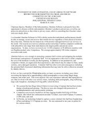
AIR OUTLET IDENTIFICATION PLAN ROOMS NOS. 53,54,7
CONSTRUCTION TECHNOLOG INC. TEST I11POi1"1"<br />
Air Outlets Snack Bar<br />
"qO3ECT---Ileo,xt._Bu.Lldg._2lS_amp_Leaeune._ SYSIEM -Dress|.ng.Roolns._&_ToLlel;..<br />
OUTLET MANUFAC]UIIIIII Titus<br />
TEST AI’I’AIIAIU8 Alnor Test Ilood<br />
Snack Bar<br />
No. 84<br />
PL84<br />
No..84<br />
Xo. 84<br />
No. 84<br />
Hens Toilet<br />
-o. 83<br />
Hens Dress,<br />
o. 80<br />
8O<br />
omes<br />
Dress No.Sl<br />
NO. 81<br />
Womens Toll<br />
No] 82<br />
No. 82<br />
|I|. VI’R<br />
SBZ CD<br />
SBt..CD._.<br />
SB5 CD<br />
SB6 CD<br />
SB7 CD<br />
H2 ER<br />
H3. CD<br />
H4 CD<br />
_L ..8..G_..<br />
IIII I.I<br />
24x24 12<br />
24x24 10<br />
.4._24__ zo<br />
2_4_x_2_4... LO_<br />
z_4_.x_..z.4., to_.<br />
Z.4..x.Z.4 to__.<br />
2..4.x._2_4.. _e__<br />
lOxlO lO<br />
4x24<br />
4x24 10<br />
zA_ _x.Z__ Lz_<br />
.4x24 8<br />
..4..2.4_ _L.<br />
.4x2il B<br />
!._O.x_,__ !L<br />
!_o.x__ lo<br />
I: I" ll,I<br />
N/A<br />
60<br />
360<br />
36O<br />
350<br />
!1_5<br />
!...o.<br />
200<br />
275<br />
ql.<br />
250<br />
150<br />
!_o_<br />
-_.0_-__...<br />
II! Illltl<br />
IiAI E Sept .7, 1988 IIEAI)II,I(i IIY, James Glenn<br />
I" III^L<br />
2313<br />
_3,5_o<br />
36Q<br />
355<br />
370<br />
.3.,4_o_<br />
150<br />
240<br />
200<br />
255<br />
250<br />
240<br />
440<br />
155<br />
go_o_<br />
RETURN<br />
SUPPLY<br />
SUPPLY<br />
SUPPLY<br />
EXIIAUST<br />
SUPPLY<br />
SUPPLY<br />
SUPPLY<br />
SUPPLY<br />
RETURN<br />
SUPPLY<br />
EXIIAUST<br />
E___XIJAUST<br />
2.16 2.30
AIR OUTLET IDENTIFICATION PLAN ROOMS NOS. B0,81,82,83,84<br />
Page 2.17 of 2.30
All] OUTI.Er.<br />
_<br />
TEST I]Er)oITI"<br />
CONSTRUCTION TECHNOLOGy INC.<br />
__<br />
"qOJECT Renovate Building 2615 Cmp Leaeune, /;YSIliM Air 0utlets International Bar<br />
UUILEI" MANUFACILIIII:I1 Titus "IESI’ AI’I’AIIA’[US Alnor Test Ilood<br />
.^ o,,oo. o, s..o<br />
l| nV I1: I<br />
Revl.ed’<br />
Illl, I1,{ I11:, eC, !1.1<br />
.,<br />
vii. I:11,1 t11.1 1’1,<br />
lnt’l Bar ]BI CD 24x24 12 575 361 360 SUPPLY<br />
,o, 19 ][..p 24 750 471 470 SUPPLY<br />
P,. 19 IB .Q...24x ".P 33_ SUPPLY<br />
la..cO._.. 1j_ _515 1.36L 1_36<br />
N9. IS5 CD_. 2x2. 703 1442 440_. _SUPPLY.__<br />
Ho, 19 .E .P ,X.24 .1:. 703 442 440 SUPPLY<br />
No, 19 ]B CD 2]g 12 _ ...<br />
545 342 345 SUPPLY<br />
Ho, 19 2_4_4 12 545 342 340 SUPPLY<br />
No, 19 [..E_. Z4. 1...... q SUPPLY<br />
,po,<br />
. . .. 19 l.lo ....’ 24.4 .?q3 4.4 .q_4.E. SUPPLY<br />
!ql! .P_...24x24 !.2_ .q 42. SUPPLY<br />
Ho., 19 lJ 24x. 1Z 4 3 SUPPLy__<br />
Ho,J__ 13 .CO 424 .J- .545 13_4Z 14<br />
L__ IB14 CD_...82..X...545 [ 342 ].340_ .JUEELL<br />
.o. z9<br />
NO, 19 IB16 CD .2_4x24. 12 545 342 345 SUPPLY<br />
Ho, 19 IBIS: ""-- 24x24 _ _ !2 ._ 560 32 350 SUPPLY<br />
o. z9 [PP L. ?. z.2 ?. 74. SUPPLY<br />
Ho, 19 I.,R_ .2.._ _L... I..H/_ RETURN<br />
.o._ z9 l.] ...Hl NIA IQO JEUe<br />
Ho. z9 fez] eG_ ZxZ L .HI& HIA 5]0_.<br />
No. 19 IB2.RL. JEUBI<br />
240 ETUR<br />
. NIA<br />
NO, ]9 lB23 RAG 2x[ I ’ ’--<br />
eurn air grilles are lay-ln type; No duc connecLlons Above cel]lng Is a return<br />
alr penum ReLurn alr duct system not changed under this contract.<br />
I)AIF_ Sept. 14, 198_8__ III!AI)III(}. I}Y aa____m_e.s__.G_I._n...n.<br />
2.18 2.30
AIR OUTLET IDENTIFICATION PLAN ROOM NO. 19<br />
Page 2.19 of 2.30
CONSTRUCTION TECHNOLOG INC.<br />
oqOJECT Renovate Butldtng 2615<br />
UUTLEI" MANUFAC]UIIL:FI Titus<br />
Den Bar<br />
No. 30<br />
_No’.’. 30<br />
I.<br />
Nn_<br />
No.. 30<br />
-No. 30<br />
No. 30<br />
No. 30<br />
"No. 30<br />
No. 30<br />
FIEMAIIKs:<br />
DB1<br />
DB5<br />
DB6<br />
D_B_7.<br />
DB8<br />
DB___g<br />
CD 24x24 10<br />
.D<br />
CD<br />
CD<br />
CD<br />
CD<br />
.R...<br />
.B.G<br />
P_4x24 -14_<br />
24x24 14<br />
24x24 14<br />
2_._4.x_2..4.. 14<br />
2_X_24_. _!.4__<br />
2_4_x.B_.<br />
24X.48<br />
Camp LeJeune 5YSIEM Air Outlets Den Bar<br />
(:FM VrL<br />
300<br />
95O<br />
30_o_.<br />
95O<br />
95O<br />
.9_o.<br />
950<br />
.NZA...<br />
NIA_<br />
TEST AI’I’AIIATUS Alnor Test Hood<br />
Revi ed.<br />
VI .IrI VII<br />
#.I I1 I<br />
DAIE __Sept. 15 19___8_8.__ IIEADINGS BY ----James..Gl.enn<br />
194<br />
60’.<br />
194<br />
6O5<br />
6O5<br />
605<br />
6O5<br />
N/A<br />
.N!A.<br />
I" III/1,1.<br />
Vl’l. i. r hi<br />
AIA OUTIJZr.<br />
"IE51" IlSPOlTr<br />
190<br />
585<br />
205<br />
570<br />
620<br />
615<br />
510<br />
1950<br />
@20<br />
SUPPLY<br />
SUPPLY<br />
SUPPLY<br />
SUPPLY<br />
SUPPLY<br />
SUPPLY<br />
SUPPLY<br />
SUPPLY-<br />
RETURN<br />
RETURN<br />
2.20 2.30<br />
PA(IE OF
CONSTRUCTION TECHNOLOG INC.<br />
AIFI OUTI.ET<br />
TEST I EPOltT<br />
Air Outlets Offices OCWt<br />
qOJECT_R,enovate _Buildtnq 2615, ,Camp LeJeu_n._e__ SYSII:’M __Co_r,Ed_d_o._r.s_...-..Regjmena]__Room<br />
UUTLEI" MANUFAC1 UIIF fl __T_J.t,US_ lEST AI’I’AIIATUS -_.A1 nor._Test ttood<br />
AII|A<br />
|[ I| VEI)<br />
Offic__e_29__<br />
Office 28<br />
Office 28<br />
Office 28<br />
Cor___r I<br />
do_r__26_<br />
Cbrf|dor 26<br />
Cr_OZ.<br />
:_OZ.<br />
,eglmental<br />
Room.No. 24<br />
1o. 24<br />
1o. 24<br />
1o, 24<br />
o, 24<br />
_Nn_ 1R<br />
’No. 18<br />
REMAIIKS:<br />
O_FJ<br />
OF3<br />
OF<br />
C__<br />
C_4_<br />
RR1<br />
RR2<br />
RR___4.<br />
RRS_.<br />
R_R_6_<br />
_)w_3.,<br />
;O<br />
V<br />
;D<br />
A_G_..<br />
L_A_G__.I<br />
s,z: Nec<br />
_POx24 -12-<br />
.4x24 12<br />
2_4x]__2 ._12<br />
L4x__24__<br />
._4.xL4_.<br />
!.4x24<br />
!4x24..<br />
’.4x24<br />
:4x24<br />
.4...x...2._4_._<br />
.4..2_..4...<br />
4-x.4-;<br />
lie $1l|tl<br />
I’M vrj.<br />
.58._3_._<br />
.5B3_<br />
N/A<br />
583<br />
..NLA_...<br />
1..__2 3_4_2_<br />
1__o__<br />
.I..4__ NIA.<br />
.110_. 342<br />
12. 342..<br />
12 464<br />
12 464<br />
12 464<br />
_1_2_ _4..6_4.<br />
_.x2_4 N_/A__<br />
1155<br />
z1551<br />
}x3.___0 N../._A_<br />
I)AIE_Sept. 16, 1988_ READINGS BY<br />
Revt .ked<br />
Vl l..ll VlI.I<br />
(LI I.I (’1<br />
James Glenn<br />
406<br />
406_<br />
N/A<br />
406<br />
NIA..<br />
2.39..<br />
NI.A..<br />
N/A<br />
38l.<br />
164<br />
164<br />
164<br />
V.A_..<br />
Ig_<br />
!!._.,<br />
Prelim.<br />
3._6.0_.<br />
700<br />
410<br />
395<br />
._2.0..<br />
27.o.<br />
230_<br />
230..<br />
590<br />
295<br />
49O<br />
470<br />
1140<br />
!0-_s.o_<br />
9001<br />
VlTI. .<br />
r I,,,I<br />
r IIIAL<br />
.38__9_0<br />
3B0__<br />
700<br />
370<br />
395<br />
_.8.0-<br />
Jill<br />
L40__<br />
!30__<br />
65<br />
.65<br />
50<br />
65<br />
1401<br />
.050.<br />
05__.I<br />
95-_.I<br />
100<br />
IIElAflll|<br />
_UPPLY<br />
RETURN<br />
SUPPLY<br />
RETURN<br />
SUpp_L.y___<br />
RE_TU_R___<br />
_RETURIL__.<br />
._sup.pLy____<br />
_SUPPJ_Y___.<br />
SUPPLY<br />
SUPPLY<br />
SUPPLY<br />
SUPPLY<br />
RETURN<br />
RETURN<br />
PPLY<br />
ULY---._<br />
RETURN<br />
.2.2___1._ o, 2_.3_0_
[]<br />
AIR OUTLET IDENTIFICATION PLAN ROOM NOS. 07,18,24,26,28,29,30<br />
Page 2.22 of 2.30
CONSTRUCTION TECHNOLOG INC.<br />
DqOJECT Renovate Building 2615 Camp LeJeune<br />
UUTLEI" MANUFACIUIIFR<br />
No. 42<br />
No. 42<br />
No. 42<br />
No. 41<br />
No. 41<br />
No. 41<br />
I)AIE Sept. 19, 1988<br />
Titus<br />
lie<br />
I+" I l,t VI-I.<br />
1613<br />
1613<br />
1613<br />
.N_I<br />
N/A<br />
I613_<br />
1613<br />
1613<br />
1613<br />
[613<br />
1613<br />
1300<br />
1300<br />
SYSIEM<br />
IESI AI’I’AIIATU$<br />
’Revised<br />
Vl I..I Vlt .111<br />
li I’I<br />
819<br />
819<br />
819<br />
N!_<br />
NIA.<br />
8_1_9._<br />
819<br />
819<br />
819<br />
819<br />
819<br />
IIEAI)INGS IIY ,James_ .G_lenn_<br />
AIR OUTLET.<br />
"rEST REPOITr<br />
Air Outlets Carolina Dining<br />
Alnor Test Hood<br />
vrl. CrM<br />
840<br />
860<br />
880<br />
885<br />
1920<br />
235O<br />
815_<br />
775_<br />
795_<br />
775<br />
785<br />
780<br />
2]0__<br />
26[L.<br />
290<br />
285<br />
270<br />
270<br />
?85<br />
SUPPLY<br />
SUPPLY<br />
SUPPLY<br />
SUPPLY<br />
RETURN<br />
RETURN<br />
_SUPPLY.___<br />
__SUPBL__<br />
_SUPPLY<br />
SUPPLY<br />
SUPPLY<br />
SUPPLY<br />
EXHAUST<br />
EXHAUST<br />
._TURN<br />
_BETRN<br />
___UPL___<br />
+_SUPEL<br />
SUPPLY<br />
SUPPLY<br />
SUPPLY<br />
SUPPLY<br />
suPPLY
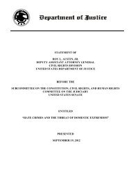
AIR OUTLET IDENTIFICATION PLAN ROOM NOS. 41 & 42
CONSTRUCTION TECHNOLOG’ INC. AIR OUTI.Er.<br />
TEST lil_llTr<br />
"qOJ’CT R_____en_goyi!teB__uJ_1_d.ln.Z515 Camg_LedeunL SYSIFM JHc.Outlets..-._Dlnln0_nm,_Lt,afete,la<br />
UUTLET MAHUFACTUIII:.ll __TJ tus TESI" AI’I’AIIATUS --.Alnor_IesLllood<br />
_Qlnlng_Bj<br />
..J. 43<br />
-.No._43_.<br />
-No. 43<br />
No.. 43<br />
No. 43<br />
No. 43<br />
No. 43<br />
No 43<br />
__CJLterJL.<br />
Rm. No. 44<br />
No.,-44<br />
No,. 44<br />
No. 44<br />
No. 44<br />
No. 44<br />
No, 44<br />
_’No. 44<br />
No.44<br />
REMARKS:<br />
I]R?._ CD<br />
DR3. CD__.<br />
DR4- CD.-.<br />
DR___ .Cp<br />
D_R_7 c_p<br />
o,RIC B61<br />
C^I. CP<br />
CA3. CD_.<br />
:A_]s_ c_p<br />
A8_ CD___.<br />
:A9 RAG<br />
O|IIL[I<br />
DATE Sept. 22, 1988<br />
I)E<br />
I’- |" ,1 Vl’l.<br />
’,.46/_<br />
.,.452.<br />
462<br />
.457<br />
...4_62<br />
45.7<br />
.45_7.<br />
..PL_A.<br />
.H/A<br />
H/A<br />
481<br />
48I<br />
481<br />
.3.<br />
..5..<br />
200_<br />
,330<br />
N/A<br />
./._...<br />
.Nl_<br />
..A_I<br />
.’Revised<br />
2OO<br />
2OO<br />
200<br />
2OO<br />
2OO<br />
PI_A<br />
2.o.fi..<br />
206<br />
205...<br />
140<br />
!.4.._o_<br />
.1.4o_<br />
141_<br />
.NLA.<br />
N/..A:.<br />
IIEAI)IHGS I)Y ._James...Glen<br />
vrl. I:fM<br />
19,5<br />
195<br />
200<br />
..o..o._.<br />
..o.p_<br />
ZOO_.<br />
1050<br />
5.40_<br />
350_<br />
175<br />
170<br />
195<br />
185<br />
105_<br />
IA5_<br />
115-<br />
43O<br />
600<br />
3_2o__<br />
250_<br />
SUPPLY<br />
SUPPLY<br />
SUPPLY<br />
SUPPLY<br />
.SUPPL__<br />
_RETURH<br />
RETIIRN_<br />
.RETURN____<br />
SUPPLY<br />
SUPPLY<br />
SUPPLY<br />
SUPPLY<br />
.SUPILY_.__-<br />
.SUPPLY___<br />
SUPPLY<br />
.SUPPLY<br />
RETURN<br />
RETURN<br />
RETURN<br />
REIURN__<br />
REILIRN
AIR OUTLET IDENTIFICATION PLAN ROOM NOS. 43 & 44
CONSTRUCTION TECHNOLOGI INC.<br />
All1 Ore’LEt,<br />
TEST llEPOITr<br />
prlOJECT---BeDOa],e But]dtzLg_Z61eJeunL SSIEM .Air_Out.lets..-._LeJeune_Boom<br />
OUXLET MAHUFACIUIII:’II Titus<br />
TEST AI’I’AIIA]US Alnor Test Ilood<br />
No. 36<br />
No; 36<br />
No. 36<br />
,o..36<br />
No. 36<br />
Ilo.L__<br />
Ho_,JL<br />
’ln. 3<br />
LeJeune<br />
Lobby No. 3!<br />
No. 35<br />
No, 35<br />
No, 35<br />
No, 35<br />
Ho. 35.<br />
LeJeune Bar<br />
No, 37<br />
REMARKS;<br />
m LRI CD<br />
LR2 CD<br />
LR3 CD<br />
LR...4 .C_0<br />
L.B_6..C.p<br />
LU_ D.__,<br />
U]IL RAG..<br />
LRlC RAG.<br />
LL| CD<br />
LL2 RAG<br />
LL3 RAG<br />
:L_4_ SY.G_..;<br />
:L.__ .S_G._<br />
,LL<br />
:BI CD<br />
.B2 RAG<br />
I)II LI:<br />
,,.r Neck<br />
24x24 :14<br />
24x24 :14<br />
24x2;4 14<br />
z_.x..z._, j_<br />
Z.4x24..H.<br />
z..4t<br />
Z.4xZ4_ _18_<br />
7_4x24_.<br />
Z4x24. _18.<br />
]6x36 6x36<br />
!4x30 18<br />
!4x30 :18<br />
Lz. x..e__, !.Zx__8_<br />
!_z..x..8. i._E_<br />
[ZzB:_. _8__.<br />
!2x32 t7x2(<br />
!4x28 :18<br />
I1| IIIIll<br />
I:l’t,I vrL<br />
77O<br />
’770<br />
770<br />
7!_0.<br />
..77o..<br />
77.0<br />
..77.0_<br />
..ilia<br />
.NIA<br />
NIA<br />
30|5<br />
N/A<br />
N/A<br />
..6_.0..5.<br />
..3__05<br />
...3.0_5_<br />
.HI.<br />
2230<br />
N/A<br />
I)^IE_ ept. 28, 1988 I1EAI)IIIG] 13Y,<br />
Revtsed<br />
VI I,,ellOivl<br />
l.l I.| I’1 14<br />
361<br />
1.36_L<br />
361<br />
361.<br />
N/A..<br />
I/A..<br />
IN/A<br />
INIA..<br />
1,1.5<br />
NLS_<br />
_: NI,_.<br />
2.B._4_<br />
!_4_3<br />
.]4..3..<br />
N/A<br />
James Glenn<br />
I, 10.46<br />
IN/A.,<br />
vrl.<br />
II I^L<br />
48O<br />
48S<br />
490<br />
9__o<br />
..4.9P_.<br />
1.27Q..<br />
320_<br />
_40_<br />
250<br />
llO0<br />
74Oi<br />
630<br />
:..-.... IlZQO<br />
:1050<br />
440<br />
IIIMIIIII<br />
SUPPLY<br />
SUPPLY<br />
SUPPLY<br />
SUPPLY<br />
SUPPLY<br />
_RETURL<br />
_BETURIL__<br />
_RETURL<br />
._RE]URN___<br />
SUPPLY<br />
RETURN<br />
RETURN<br />
._}pLY<br />
SUPPLY<br />
SUPPLY<br />
EXUST<br />
2.27 2.30"
AIR OUTLET IDENTIFICATION PLAN ROOM NOS. 35,36,3<br />
II<br />
Page 2.28 of 2.30
CONSTRUCTION TECHNOLOQI INC.<br />
DqOJECT<br />
Renovate Building. 2615<br />
UUTLET MANUFAC1UIII:Ii Titus<br />
_Federal<br />
Cashier 09<br />
Cashier 10<br />
"Jan C] 12<br />
..No. 07<br />
LOUOOe_NO.][<br />
Hens Tlt.<br />
No. 20<br />
No. 20<br />
o__q2L<br />
Board Room<br />
No. 14<br />
No. "14<br />
No. 14<br />
IIEMAIIKS:<br />
FL 1 _C,D_..<br />
FI,.Z E.,._.<br />
JCl ER<br />
.C_R._2 C..D.<br />
HI. CP._.<br />
W_ ER_..<br />
N3.. C.I<br />
N4_ ELL__.<br />
HI CD<br />
M__Z F_D__<br />
M3 .E..R._..<br />
BRI CD<br />
BR2 CD<br />
e__e3 :_D_.<br />
BR4 CD<br />
Oil I.l.<br />
30x36 .3.0x__3.,<br />
... _.<br />
24x24 12"<br />
9x9 I0<br />
9x9 10]<br />
9x9 I0<br />
9x9 I0<br />
All{ OUI’I.Ei:<br />
TEST I1EPOITr<br />
Air Outlets Federal Lobby<br />
Camp Le__Je.u..ne SYSII:’M Cashters- Toilets Board Room<br />
I:I’M Vl.<br />
..2..!_3o_<br />
:B/A_.<br />
..s_<br />
..!__<br />
4.10<br />
44<br />
4.4O.<br />
_4.0<br />
2931<br />
.2__93__!<br />
..z._7.0__<br />
..3_,0...<br />
-|--.]<br />
155<br />
1551<br />
.1551<br />
"lEST AI’I’AIIA’|US Alnor Test Ilood<br />
Revised<br />
Vl I,. II, VlJ,lq<br />
I.I I’I tl<br />
DAIE _Sept. 2 4___198.__8.._ IlEAl)Ill(IS IW ___J_.m..e._s_G..l...e.:n...n.<br />
1433<br />
N/A<br />
LSQ_<br />
1.5Q<br />
24<br />
79<br />
79<br />
231<br />
173<br />
231<br />
173<br />
153<br />
153_<br />
10.6.<br />
142-<br />
81:<br />
Bi:.:<br />
81.--"<br />
vrl.<br />
250<br />
1200<br />
320<br />
180<br />
3O<br />
225<br />
260<br />
.__<br />
140<br />
290<br />
I5Q._<br />
300<br />
300<br />
150<br />
150<br />
130<br />
130<br />
130t30<br />
SUPPLY<br />
RETURN<br />
SUPPLY<br />
SUPPLY<br />
EXIUST<br />
SUPPLY<br />
SUPPLY<br />
EXHAUST<br />
SUPPLY<br />
SUPPLY<br />
SUPPLY<br />
EXIIAUST<br />
EXIIAUST<br />
-SUIPLY<br />
SUPPLY
AIR OUTLET IDENTIFICATION PLAN<br />
ROOM NO$.01,07,O9,I0,12,14,16,17,20<br />
Page 2.30 of 2.30
DESCRIPTION:<br />
TAB PLACEMENT HERE<br />
Tab page did not contain hand written information<br />
Tab page contained hand written information<br />
*Scanned as next image<br />
Confidential Records Management, Inc.<br />
New Bem, NC<br />
1-888-622-4425<br />
9/08
TAB AGENDA<br />
2.<br />
3.<br />
4.<br />
5.<br />
Design Review<br />
TABLE OF CONTENTS<br />
Work Strategy and Schedule<br />
Simulated Loads<br />
Seasonal Restrictions<br />
Support Requirements
1.1 Design Review<br />
A. General:<br />
A review has been made of the contract plans and<br />
specifications in an attempt to determine if all<br />
components such as balancing valves, thermometers<br />
pressure gauges, etc. have been provided in the<br />
contract documents to adequately test and balance<br />
the HVAC system(s)<br />
B. Description of Facility:<br />
This facillty is an Officers Club used for<br />
recreational purposes and is complete with Club<br />
Room Bars, Dining Areas, large kitchen, Pool-<br />
Snack Bar, arber Shop, Office Areas and<br />
Conference Rooms. It is used for social<br />
gatherings, banquets, food and drink service,<br />
and is normally open six days a week, Tuesday<br />
through Sunday.<br />
Building This facility is a one story<br />
building with a small second floor office which<br />
is really unaffected by the TAB work The<br />
building is basically a wood frame brick veneer<br />
structure having an underfloor crawl space and a<br />
relatively large attic space. Both the attic<br />
and crawl space are cross ventilated by natural<br />
draft ventilation and the ceilings are insulated<br />
with various types of blown in and blanket type<br />
insulations.<br />
HVAC Systems The basic system is a four pipe<br />
chilled and hot water system which is served by<br />
two centrifugal water chillers and two high<br />
pressure steam boilers along with hot water<br />
converters. The original space heating was<br />
provided by steam radiators and a couple of<br />
those still exist in this building. No new work<br />
has been performed on the chilled water system<br />
except the extension of some piping to the new<br />
AHU cooling coils. The heating piping system<br />
however was modified quite extensively because<br />
of asbestos insulation that had been used on the<br />
hot water and steam lines. A new deaerator and<br />
condensate feed water system was provided for<br />
the existing steam boilers and new steam to hot<br />
water converters and pumps were provided for<br />
generating building hot water Two new air<br />
handllng units were provided for the Snack Bar<br />
and Food Storage Areas and a new make-up air<br />
handler was provided for the existing range hood<br />
in the Snack Bar. Six new chilled hot water
fan coll units were provided for various offices<br />
the Break Room and the Barber Shop. Six new<br />
roof exhaust fans were provided for added<br />
ventilation and the balance of the HVAC system<br />
utilizes existing AHU, fans, etc. that have been<br />
unchanged under this contract. All air<br />
distribution is from over head and most of the<br />
chilled, steam and hot water piping Is below the<br />
floor in the crawl space. At1 controls Involved<br />
in this part of the contract are pneumatic and<br />
will be reused except where speclflcally called<br />
for otherwise.<br />
C. Changed Conditions:<br />
The building was originally constructed in the<br />
forties but has been expanded and added onto on<br />
several different occasions. Consequently the HVAC<br />
systems were modified with each of these additions.<br />
During the seventies there was a major change to the<br />
HVAC system and a central chilled water system was<br />
installed and possibly the boiler plant modified.<br />
New air handling equipment was provided In most<br />
areas and the duct system was also changed.<br />
Unfortunately however all those changes were not<br />
reflected in the plans and specifications in this<br />
contract and as a result a considerable amount of<br />
actual Installed conditions exist that are not shown<br />
in the contract documents. In a co-operatlve spirit<br />
the owner and the contractor worked together in<br />
making the necessary modifications to install the<br />
system (primarily duct work changes). In some cases<br />
alr outlets were eliminated or changed while in<br />
other areas outlets were added In any event the<br />
changes were never intended to reduce or add to the<br />
total air being delivered to a given space. The<br />
criteria emphasized by the ROIC is that the finished<br />
product produce the heating and cooling effects as<br />
designed. However, it was agreed that If necessary<br />
the air flow could very from the plan CFM as much as<br />
15 20 percent If absolutely necessary, but that<br />
the TAB contractor would strive to match the CFM to<br />
+/- 10 percent.<br />
D. Assumptions:<br />
It has been assumed that the existing air<br />
handling equipment which is being reused is<br />
adequate to produce the CFM as shown on the<br />
drawings.<br />
It has been assumed that the filters on the<br />
reused equipment will be replaced by the owner<br />
before TAB is started.
3. It is assumed that all existing AHU coll are<br />
balanced and no work will be required on those<br />
units<br />
4. It is assumed that the existing pumps have the<br />
capacity and pressures required to deliver the<br />
specified flow rates to the equipment.<br />
It is assumed that all existing fan systems<br />
which were not changed under this contract will<br />
be functioning but the time the TAB operations<br />
begin<br />
It is assumed that all existing control systems<br />
which were not changed under this contract will<br />
be functioning but the time the TAB operations<br />
begin.<br />
It is assumed that the contractor shall have<br />
full access during normal working hours to all<br />
areas involved for the TAB operations.<br />
*The owner’s maintenance personnel will have to<br />
perform some work before these systems are fully<br />
functlonable.<br />
E. Adequacy of Design:<br />
General The plans and specifications (along<br />
with on site observations) have been reviewed<br />
for the purpose of determining the procedures<br />
and techniques required for proper TAB of the<br />
various air and water systems.’" (No<br />
consideration have been given to testing steam<br />
rates, condensate flow rates, quallty of steam,<br />
etc., as that is beyond this contract<br />
requirements.<br />
No evaluations of heating and cooling loads, air<br />
and water flows requirements, comfort<br />
conditions, etc., have been made as it is<br />
assumed these were taken into consideration by<br />
the design engineer. From our examinations we<br />
have found several pieces of equipment that have<br />
not been provided with sufficient devices to<br />
enable an accurate TAB. While close TAB can be<br />
performed, which is common in the commercial<br />
industry, the requirements to meet NEBB or AABC<br />
standards will require that additional devices<br />
be added as follows:<br />
a) Balancing Value and Flow Sensors on<br />
steam/hot water converter
e<br />
Balancing Value and Flow Sensors on the<br />
Fan/Coll Units<br />
Flow Orflces in the Steam supply to the<br />
hot water converter<br />
Pressure Gage connections on Pumps and<br />
steam/hot water converter<br />
Thermometer wells on steam/hot water<br />
converter
2. Work Strategy and Schedule:<br />
All TAB shall be done in full accordance with the NEBB<br />
.methods and procedures as hereinafter described.<br />
It has been assumed by the TAB contractor that the<br />
existing equipment and the chilled and heating water<br />
systems were and are operating satlsfactorily and<br />
performing as intended. No adjustments to any of this<br />
equipment (nor cost for same) has been included in this<br />
TAB Contractors price. Any adjustments that may be<br />
required on the existing equipment shall be performed by<br />
others or as an add to the TAB Contract.<br />
The TAB work shall be performed on each of the air<br />
distribution systems (meaning all areas supplied by<br />
individual air handling system) as a separate TAB<br />
operation. This method will provide the least amount of<br />
disturbance to the activities of the facillty while<br />
performing the TAB. However, because each air handling<br />
units serves several different rooms it will not be<br />
possible to completely balance one room at a time. The<br />
TAB work may require re-balanclng each room two or three<br />
times untll the entire system is balanced. The areas<br />
constituting systems are as follows:<br />
Equipment Area Served TAB Time<br />
New AHU-I:<br />
Air Apparatus Test<br />
Apparatus Coll Test<br />
"Air Outlet Test<br />
New AHU-2:<br />
Air Apparatus Test<br />
Apparatus Coll Test<br />
Air Outlet Test<br />
Exlstinq AHU-I:<br />
*Air Outlet Test<br />
Existlnq AHU-2:<br />
*Air Outlet Test<br />
Exlstinq AHU-3:<br />
*Air Outlet Test<br />
Existing AHU-4:<br />
*Air Outlet Test<br />
Dry Storage 67 1 Day<br />
Womens Dressing Room 81<br />
Womens Toilet 82<br />
Mens Toilet 80<br />
Mens Dressing Room 83<br />
Snack Bar 84<br />
i Day<br />
International Bar 19 2 Days<br />
Den Bar 30 I Day<br />
Carolina Room 42<br />
Dining Room 43<br />
Cafeteria 44<br />
Service Corridor 41<br />
LeJeune Room Lobby 35<br />
LeJeune Room 36<br />
LeJeune Room Bar 37<br />
1 Day<br />
2 Days
Equipment<br />
Exlstinq AHU-5:<br />
*Air Outlet Test<br />
Exlstlnq AHU-6:<br />
*Air Outlet Test<br />
Exlstinq AHU-7:<br />
*Air Outlet Test<br />
Area Served<br />
OCW Room 18<br />
Regimental Room 24<br />
Federal Lobby 01<br />
Corridor 07<br />
Cashier Waiting 08<br />
Cashier 09<br />
Cashier 10<br />
Passage 11<br />
Mens Toilet 13<br />
Women’s Lounge 16<br />
Women’s Toilet 19<br />
Board Room 14<br />
Office 28<br />
Office 29<br />
Corridor 26<br />
Exlstinq AHU-8: Tower Room 201<br />
*Air Outlet Test<br />
New FC #1: Office 57<br />
*Terminal Unit Coll Test<br />
New FC #2: Office 60<br />
*Termlnal Unit Coil Test<br />
New FC #3: Breakroom 48<br />
*Terminal Unlt Col1 Test<br />
New F__qC : Prep Room 47<br />
*Termlnal Unit Coll Test<br />
Ne___w F__qC #_4: Office 103<br />
*Terminal Unlt Coll Test<br />
New FC #5: Barber Shop 27<br />
*Terminal Unlt Col1 Test<br />
New F-l: Men’s Toilet 83<br />
*Fan Test<br />
New F-2: Ice Room 49<br />
*Fan Test<br />
New F-3: Women’s Toilet 54<br />
*Terminal Unit Coll Test<br />
New F-4: Boiler Room 51<br />
*Fan Test<br />
2 Days<br />
1 Day<br />
N/A<br />
I/2 Day<br />
1/2 Day<br />
1/2 Day<br />
1/2 Day<br />
1/2 Day<br />
1/2 Day<br />
1/4 Day<br />
1/4 Day<br />
1/4 Day<br />
1/4 Day
Equipment Area Served TAB Time<br />
New F-5: Boiler Room 51 1/4 Day<br />
*Fan Test<br />
New F-6: Men’s Toilet 13 1/4 Day<br />
*Fan Test<br />
H. W. Converter: Mechanical Room<br />
*Heat Exchanger/Converter Test<br />
Htg. Water Pump<br />
*Pump Test<br />
1/4 Day<br />
Mechanical Room 1/2 Day<br />
*See Test Report Forms Section III for Extent of Test.<br />
Rev. 81588<br />
The total estimated time for the TAB work is less than<br />
three weeks (17 working days) and hopefully that can be<br />
reduced to about a week and a half. In any event there<br />
are no restrictions on the TAB work as to which systems<br />
are tested first. To accommodate the owners needs, we<br />
suggest that they select the order in which the TAB is to<br />
progress so as not to interfere with the club operations.<br />
They should keep in mind that all TAB work has been<br />
estimated on normal eight hour work days. A11 TAB can<br />
start as early as August 15, 1988 and hopefully no later<br />
than August 17, 1988.<br />
The instruments that will be used for the TAB work is<br />
llsted in section III.
BASIC AIR SYSTEM<br />
PROCEDURES<br />
"Preliminary TAB Procedures" covered<br />
Ihe preparation work lhat must he done prior !o Ihe<br />
actual testing, adustiqg and bnlnnP.in.q of tile IVAC<br />
systems on the Job. Confirm Ilmt lhese peliminnry<br />
procedures have been completed and check lisls<br />
prepared. Do not attempt to balance a system before<br />
Installation has been completed and the system is<br />
ready to be balanced.<br />
The following balancing procedures are basic Io nil<br />
types of air systems.<br />
1) Confirm Ihat every ilem affecting tile aiHIow of a<br />
ducl system Is ready for tile TAB woJk, such as<br />
doors and windows being closed, ceiling liles<br />
(return plenums) in place, etc.<br />
2) Confirm Ihal all aulomalic control devices will<br />
not affecl TAB operations.<br />
3) Establish the conditions for Ihe maximum demand<br />
system airflow which generally is a cool-<br />
4)<br />
Ing application with "welled" coils.<br />
After verifying Ihal all dampers are open or set,<br />
sled all related systems (relurn, exhaust, etc.)<br />
and the system being balanced with each fan<br />
running al Ihe design speed (rpm). Upon start-<br />
Ing each fan, #Immdiately check 11m fnl reeler<br />
amperage. If lhe amperage exceeds lhe<br />
nameplale full load amperage, slap the fnn Io<br />
delermine lhe cause or Io make lhe necessary<br />
adjuslmenls.<br />
5) Again confirm Ilml 11 related syslPmfs|vleg<br />
each nrP.n wilhin Ihe space b.h|.q<br />
are operaltng. If Ihey are not, prn.ure differences,<br />
and Inlillrnlion or exfiltralion may adversely<br />
influence Ihe balancing. Pceliminnry<br />
studies will have revealed whether or not Ihe<br />
supply air quanlily exceeds lhe exhausl air<br />
qunnlily from each area. Positive and negalIve<br />
pressure zones should be Identified at the time.<br />
6) If a supply fan i. connected to a rolurn air syslem<br />
and an oulside air inlake, sot 11 syslem<br />
AIR SYSTEM AB<br />
PROCEDURES<br />
dampers and conlrols so that the air relurned<br />
from Ihe individual rooms or areas supplied by<br />
lhe fan is relurned via Ihe relaled relurn air<br />
syslem. Normally lhis will Involve opening an.<br />
o|lsidP, air damper Io the minimum position,<br />
opeling Ihe relum air damper, nnd closing<br />
exhnusl nit nnd relief air dampers. (If lhe supply<br />
syslem is nssocinled with a return air syslem<br />
nnd/or an independenl exhaust system, make<br />
mre nil syslems are opernling and all relaled<br />
dampers are sel properly for Ihe TAB work.)<br />
7) t3elermine the volume of air being moved by lhe<br />
supply fnn nl design rpm by one or more of lhe<br />
following melhods. The preferred methods are:<br />
a) Pilol lube lraverse of main duct or dcls<br />
leaving fan discha=ge.<br />
b) Fan curves (r fan performance chads. In<br />
order 1o delermine fan performance using a<br />
fan curve or performance rating chad, il is<br />
necessary Io take amperage and voltage<br />
readings. In addition, a slallc pressure read-<br />
Ing across lhe fan must be recorded. Wilh<br />
rpm, brake horsepower and static pressure,<br />
lhe fan mnnufacturer’s data sheets may be<br />
med Io delermlne Ihe aidlow (cfm) predid.led<br />
by Ihe Hnufaclurer. Fan perfbrrnnce<br />
cnn dUvinle from Ihe fan curves if<br />
"sy.lem effect" or olher syslem installalion<br />
defecls are present.<br />
c) Anemomeler readings across coils, fillers,<br />
ned/or dampers on the Inlnke side of the fan.<br />
1-hi i used ns an approxlmalion only.<br />
0) If Ihe spply fan voh=me is not within plus or<br />
minus 10% of the design capacity at design<br />
rpm, dtermine the reason by reviewing all syslem<br />
conditions, procedures and recorded dale.<br />
Check and record the air pressure drop across<br />
fillers, ’coils, eliminators, sound traps, elc., to<br />
see if excessive loss Is occurring. Paflicularly<br />
Iudy dcl and casing conditions at Ihe fan inlet<br />
and outlel.
factor prescribed by the man(Jfactnrer for u.re in<br />
conJunclion wilh a pnrlicHlar Inslrumenle In addilion<br />
il is often necessn thai Ihe rending !<br />
grilles, regislers nnd dillusers bn Inkon in a<br />
posilion or number of positions prescribed by<br />
Ihe manulaclurer of lhe air lerminal device.<br />
9) Repeal Ihe branch bnlmcing unlil Iho system is<br />
in balance.<br />
10) Verify Ihe fan cnpacily nnd operating con(lilion<br />
again and make a final adjuslmenl in the fan<br />
ddve If necessaw.<br />
11) Veri Ihe action of all fnn shul down conlrols<br />
and aldlow safely conlrols.<br />
12) Prepare all TAB reporl forms and sbmil as<br />
required, using Ihe NEBB TAB Repeat Forms<br />
SYSTEMS WitH<br />
ECONOMIZERS<br />
Follow Ihe procedures oullined for exhausl and relurn<br />
air syslems, excepl Ihal allot balancing Ihe relure<br />
air syslem and tile associaled supply air syslem<br />
Ihe relurn air damper should be closed; Ihe inletlocked<br />
relief air damper should be opened and the<br />
relurn air fan, slalic pressure and clm should be<br />
checked again. If il is necessary to increase tile system<br />
static pressure and Ihereby reduce tile fan cfm,<br />
adjust lhe exhausl air damper 1o a maximum position<br />
less Ihan 100% open. Recheck lhe supply fan airflow<br />
with Ihe oulside air damper In Ihe full open position.<br />
OPTIONAL PROCEDURE<br />
RATIO METHOD<br />
This Is one of the olher melhods Ihal has been developed<br />
for Ihe final balancing process.<br />
1) Do all of tile TAB work un(ler Sul)-oecliofl A of<br />
tills section entitled "Basic Air System Procedures."<br />
2) Then begin balancing Ihe supply syslem al Ihe<br />
las! outlet of Ihe branch lmlhest from lhe fan<br />
(branch number 1). This is oullel number 1,<br />
number 2 is Ihe next Io lhe last oullel. Measure<br />
Ihe airflow al oullel number (Q,.) and compare<br />
wilh tile design airflow for Ihat oullet (Q,), recold<br />
the ratio (Q,./Qd).<br />
3) Measf=re Ihe airflow al outlet number 2 and<br />
delormine Ihe ratio (QJ(3d). Compare<br />
mid (Q/Q,),. If Ihese rations are eel Wilhln 10%<br />
of each olher, adjust oullel number 2 1o bring<br />
ratios Inlo closer agreement. DO NOT ADJUST<br />
OIITI ET NUMBER 1.<br />
Measme and again determine (Q,./Q,)= and<br />
(Q,,,/Q,), and compare. If lhese are wilhin 10%<br />
of each olher, no further adjuslmenl is necessary.<br />
Proceed to oullel number 3.<br />
4) Delermlne (Q.,/Qd)= and compare with (Q,,J<br />
Q.). If necessary, adjust number 3 so that<br />
(O,,,IOe) end (Q,./O,)=’db not vary by more Ihari<br />
10%. DO NOT ADJUST OUTLETS 1 OR.2.<br />
(Adjushnonl of oullel 3 aulomalically changes<br />
the (Q,JOe) ratios of oullets 2 and 1. The ratios<br />
for all Ihese oullel9 approach lhe same values.<br />
For this reason, once Ihe oullel has been adjusled,<br />
il does eel require fudher adjustment).<br />
5) Proceed to oullel number 4 and adjusl Io oblain<br />
nflmemenl between (Q.,IQ) and (Q,.IQe)=.<br />
6) Aller all oullels on branch number are propoHionalely<br />
balanced to each olher, proceed Io<br />
branch number 2, elc.<br />
Upon complelion of propodionate balancing of<br />
all outlets, the branches should .be propoHionalely<br />
balanced.<br />
7) Select typical oullels in branches 1 and 2 ..."<br />
djusl number 2 branch damper Io obtain<br />
agreement of Ihe (Q,./Qe) ratios for Ihe two<br />
branches. Proceed in like manner to obtain<br />
agreemenl between bran;hes 2 and 3, 3 and 4,<br />
elc.<br />
8) Upon completion of proportionate balancing,<br />
recheck Ihe fan,capacily. Adjust Ihe fan.speed<br />
to obtain a (Q,./Q.) ratio of 1.0 al the fan. Since<br />
the system has. been propodtonately adjusted,<br />
lhe ((.),,JO,) ratio Ihroughogt the system will be<br />
approximately 1.0 and lhe flow from each outlet<br />
will be Ihe design airflow rale.<br />
9) Then continue lhe TAB work by following all of<br />
the steps lisled under Sub-Section B--"Supply<br />
Air Syslems Procedures" found earlier in this<br />
section.
AIR SYSTEM TAB PROCEDURES<br />
10) Verify the nclton of all fan conhol dnmpm., shul<br />
down controls, and ahllow safely conlrols.<br />
11) Prepare lha required rep.od forms and .ubmil<br />
as required. (See Seclion VIII raped Iorms).<br />
XHAUST AND RETURN<br />
AIR SYSTEMS<br />
1) Follow paragraphs through 6 for exlmusl air<br />
fans end 1 Ihrough 7 for rolurn air fans under<br />
Sub-Section A--"Baslc Air Syslem Procedures"<br />
In Ihis section for return and exhaust<br />
systems.<br />
2) Delermlne lhe volume of air being moved by<br />
exhaust fan at design rpm by one or more of<br />
following methods. the preferred melhods are:<br />
a) Pilot lube lransverse of Ihe main duct or lhe<br />
ducts leaving the fan discharge.<br />
b) Fan curves or fan performance chmls. In<br />
order Io determine Ihe fan performance<br />
using a fan curve or perfornmnce rating<br />
chad, it is necessary !o lake amperage nnd<br />
vollage readings nnd calculaln lhe brake<br />
horsepower. In nddilion, a slnlic pressure<br />
reading across the fan must be recorded.<br />
IGUFIE 5-4 Oblalnlr’g nn Exhausl Ducl Velocily<br />
Wilh rpm, brake horsepower and<br />
pressure readings, lhe fan manufacturers’<br />
dala sheels may be used Io delermlne the<br />
airflow (cfm) predicled by Ihe manufa,clurer<br />
unless "syslem e!iecr’ reduces lhe fan performance.<br />
3) 1ho exhaust fan volume should be wilhin plus<br />
or minus 10% of Ihe design capacily if earlier<br />
procedures were followed. Check and record<br />
lira air pressure drop across fillers, cobs, sound<br />
Imps, etc., to see if nny excessive loss Is occurring.<br />
Parllcularly study duct and casing condllions<br />
nt Ihe fan inlel and outlet for possible<br />
"system effect."<br />
Record the exhnu! fan sgcfion slallc pressure,<br />
fnn discharge static, pressure, amperage ’and<br />
fm nmnuremenls. Confirm Ihal Ihe fan lor<br />
i not overloaded.<br />
4) If the exhaust syslem Is being balanced prior to<br />
Ihe supply and/or relurn air syslems, and if the<br />
measured cfm of nny fan vrles more than t0%<br />
from design, adjust Ihe drive of each fan Io<br />
obtain Ihe approximate required cfm. Make<br />
proliminn ttrvey, spot checking air circulnlion<br />
in vmiou arena. Then follow all procedures<br />
outlimd, nfler the exhausl system is balanced.<br />
5) Mk Pitol tuh Irnverso on nil main exhausl<br />
Htct h) dqtmmin lhe ir disIrihtJlion. Invesliqnln<br />
mW brnnch Ihnl i vn low in capncily to<br />
make ure Ihnt no blockage exists.<br />
fi) AIj’:I llq vohrm lnrpor in Ihe main ducls !o<br />
7)<br />
Wilh, d adjusting any lermial device, measure<br />
syslmn. Study nny rndicnl conditions and correcl<br />
them. Plan the eqtmnce of brnnch bnlancig.<br />
In making the ndjustmenls, it is preferable<br />
to ndjusl Ihe branch dampers rather than the<br />
dnmpms al lira air lerminals. If Ihe lhrollling<br />
I}mCnn nl n Iffrmit}nl dmpnr ivolves closing<br />
O) Woddl hem the brmch with the highesl menmred<br />
cnpacily In Iho brmch wilh lhe Iowesl<br />
mnnued cpncily, make adjuslmenls In each<br />
Ianch. Beginning wilh Ihe inlel devicemosl<br />
nlanl from lhe branch and proceeding Ioward<br />
lhe branch conneclion, make volume adjuslmeals<br />
al each lerminnl as necessa. I1 Is impoHmd<br />
Ihat Ihe balancer use Ihe proper "k"
AIR SYSTEM TAB PROCEDURES<br />
FIGUIIE 5-<br />
9) Using the methods oilllined in pnfn.qnl)tW B. (telermine<br />
Ihe volume of nit bein hnndld by n<br />
relurnnir fnn if used; and/or if a cenlral exhmsl<br />
fan syslem I used, nlo delermine Ihe c[m<br />
being handled by lhe exhnusl fan. If several<br />
exhmsI fans, such a power root venlilnlors.<br />
re related Io a parliculnr supply system, II i<br />
enerally not necessnry Io menm,e Ihe cfm of<br />
each such exhaust (an until afler lhe supply<br />
syslem is balanced.<br />
10) II Ihe measured cfm ol Ihe mpply fnn, cenhnl<br />
return fan or cer]lrnl exhausl fm varies moe<br />
thn 10% from design, ndjul Ihe (hive of ench<br />
fn Io oblain nproximnle required chn. ecor(t<br />
fan uction slalic prestr, fnn dischnrgq Inlic<br />
pressure, nmpernge nt}d cfm n)entremQ]Is.<br />
Confirm lhnl lhe fan molor i not overlonded.<br />
1 1) Make a preliminn suey, pol checking air<br />
clrculalion in various rooms. Wilh knowledge of<br />
Ihe uply nnd relurn or exhausl fnn volumes<br />
and data from Ihe suwey, delermine if Ihe re-
12)<br />
B<br />
lurn or exlra[tsl air system should be balanced<br />
before Ihe supply syslem is balanced,In conlinualion<br />
of Ihis procedural oulline, Ihe assumplion<br />
Is made Ihal Ihe supply syslem balance is<br />
nol reslrained by Ihe ehausl syslem or Ibe<br />
relurn syslem: tlowever, if such a reslrainl<br />
exisls, Ibe exhausl syslem or Ibe rehfrn syslem<br />
should be balanced prior 1o conlittuing will) lira<br />
supply syslem.<br />
The syslem is considered balanced in accordance<br />
will) Ibese procedural slandards when<br />
lbe value ol Ibe air q[fanlily ol each inlel or<br />
device is measured and found Io be wilhin 10%<br />
ot Ibe design air fluanlilies (unles Ilmre are<br />
reasons beyond lira conhol of lhe TAB lirm--<br />
SUPPI.Y AIR SYSTEM<br />
PROCEDUFIES<br />
1) Make Pilol lube Iraverses on all main s=pply<br />
and major branch ducls 1o delermine Ihe air<br />
dislribulion, h|vesligale any branch Ihal is very<br />
low in capacily Io make sure Ihal no blockage<br />
exisls.<br />
2) Adjusl Ibe vohJm, P. dampers in life main and<br />
branch ducls Io Ihe approximale airflow (clm)<br />
requirement.<br />
3) Wilhoul adjusling any lerminal device, measure<br />
and record Ibe airllow al each leminal in Ihe<br />
syslem. Sludy any radical condilions and correcl<br />
Ibem. Plan Ihe se(llmnce el branch balanc<br />
Ing. In making adjushrmnls, it is preferable Io<br />
adjusl volume dampers inslead of exlraclors (il<br />
inslalled) or Ibe dampers al Ibe air lerminals. If<br />
Ihe lhrollling process at Ibe lerminal involves<br />
closing Ibe damper !o a degree lhal generales<br />
noise, evaluale the design chn capacily of<br />
branch ducl.<br />
,4) Working from Ihe branch wilh Ibe bighesl measured<br />
capaclly 1o the branch wilh Ihe Iowesl<br />
measured capacity, make adj|Jshnenls in each<br />
branch. Beginning wilh Ibe oullel mosl dislanl<br />
Item Ihe branch conneclion and proceeding Ioward<br />
Ihe branch conneclion, make volume adlustmenls<br />
al each lerminal as necessary. I! is<br />
Impodanl Ihal lbe balancer uses Ibe proper "k"<br />
lacier prescribed by Ibe air lerminal manufaclurer<br />
for use in conjunclion wilb a padiculnr<br />
tnslrumenl. In addilion, il is necessmy Ibal Ibe<br />
readings al grilles, registers and diffusers be<br />
FIGURE 5-3 A Typical Air Diffuser Velocity<br />
Measurement<br />
taker) in a position or number of positions prescribed<br />
by the manufacturer of lhe air lerminal<br />
device.<br />
5) Flepr:nl the branch balancing unlil Ihe syslem is<br />
it) balm)ca.<br />
6) Verity Ihe tan capacity and operating condilions<br />
again and make a final adjuslment in the fan<br />
drive if necessary.<br />
7) If the supply system was tested with dry cob -"<br />
surface and is designed for dehumldificalion,<br />
the air quanlily should be checked under wet<br />
coil conditions. (Often, 10% to 15% Is added Io<br />
lhe system setting Instead.)<br />
8) After the supply and return exhaust systems are<br />
balanced, the supply fan capacity should be ,<br />
checked wilh 100% oulside air operation if Ibis<br />
alternalive is included in system design. Appropriale<br />
damper adjuslmenls should be made if<br />
necessary.<br />
9) Record Ihe "as balanced" slate of the syslem<br />
on reporl forms for all terminals and ducl appartlus.
HYDRONIC SYSTEM TAB PROCEDURES<br />
"m)<br />
n)<br />
achieve balanced circuils ns oullined ahov.<br />
Veal air from low flow circuil.. 1hen procend<br />
wilh Ihe balancing el lerminal unils on each<br />
branch,<br />
Before adjusling any balancing cocks al<br />
equIpmenl (I.e. chillers, boilers, hal water exchangers,<br />
hal waler coils, chilled waler coils,<br />
etc.) lake a complele sol of pressure drop<br />
readings Ihrough all equlpmnl and compare<br />
Ihls wilh submillal dala readings. Delermine<br />
which are high and which are low in wnler flow.<br />
Veal air from low flow circuils or unils nnd<br />
relake readings.<br />
Make a preliminnry adjuslmenl to 111o halanclag<br />
cocks on all unils with high wnler flow,<br />
selling each about t0% higher Ihnn Ihe design<br />
flow tale.<br />
Take another complol ,el of pr.nnlrre, wllage<br />
and mpere re,gdir(|r on nil pllrtl<br />
syslem. If syslom lolnl flow Im fnllm blow<br />
design flow. open Ihe balancing cock nl each<br />
pump discharge Io bring Ihe flow al each pump<br />
FIGURE 7-1 Balancing a Ilydronlc Coil<br />
wilhin 105--110% el lhe design reading (if<br />
pump capacily permils).<br />
o) Make mmlher adjtmlmenl !o Ihe balancing<br />
cocks on.all units which have readings more<br />
titan 10% above design flow in order Io increase<br />
Ihe flow Ihrough Ihosa unils wllh less<br />
lhan design flow.<br />
p) Repeal lhis process unlil Ihe.aclual fluid flow<br />
Ihrough each piece of equlpmonl is wilhin plus<br />
or minus 10% of Ihe design Ilow,<br />
q) Make a final cimck of lhe pressures and Ihe<br />
flow of .qll pmp md oquipmel;’of lhe vollage<br />
,qnd mnporage of pump motors; and record Iha<br />
dala.<br />
r) Whine IhrP.n-wy attlomalic valves are used,<br />
sol all hypa.s line balancing cocks 1o reslrlcl<br />
Ihe bypassed waler Io 90% of Itm maximum<br />
demnnrt lhmugh coils, heal exchangers and<br />
lhrr lrmiml tmil.<br />
.g) AII, :dl h,l w)l’, I:v: l]nll complnled and lhe<br />
y.hmg ;], olralin.q wilhin plus or minUs<br />
10% of desi.qn llow, mink or score all balancing<br />
cocks, gauges, and Ihermomelers al final sol<br />
poinls and/or range of operallon.<br />
I) Verify Ihe action of all waler flow safely shuldown<br />
conlrols.<br />
u) Prepare all TAB report forms and submil as<br />
equired using Iho NEBB TAB Report Forms<br />
Iotmd in Secllon VIII.<br />
SPECIFIC SYSTEM<br />
PIIUCEDUHES<br />
The basic sleps previously oullined in Seclion A form<br />
Ihe foundnlion for bnlnncin,q any hydronlc dlslribulion<br />
syslem. In lifts seclioo, ndrtilional or spp.clal balancing<br />
procedures am oullihed for use In balancing spe-’<br />
ctfic lypes of hydronic rlislr!bul!on syslems. All<br />
eqtdpmel such n.q boilers, chillers, compressors,<br />
etc., shall be started by, and operated<br />
under, the supervision of the responsible con-<br />
Iractor or the designated aulhorlly,<br />
a)<br />
Chilled and/or Hot Waler<br />
Sylems<br />
Water flow through cldllers, coils "and heal exchangers<br />
should be determined by using man-
BASIC HYDRONIC<br />
SYSTEM PROCEDURES<br />
"Preliminary TAB Procedures" outlined<br />
the preparation work that must be done prior to tile<br />
actual on the lob testing, nljusling, and halnncifg el<br />
HVAC syslems. Confirm thai these pelimimry plocedures<br />
have been compleled and thai check lisls<br />
have been prepared. The following balancing procedures<br />
are basic to all types el hydronic dislribullon<br />
syslems:<br />
a) Check to see that all necessary elecllical wiring,<br />
lemperalgre conlrol syslems, all relaled<br />
hydronic piping ctrcgils and all related ducl<br />
systems are lunclional and Ihal any necessary<br />
compensation Ior seasonal ellecls have been<br />
made.<br />
b) Determine lhal all hydronic systems have been<br />
cleaned, Iluhed, refilled and venled as required.<br />
c) Delermine Ihal all manual valves are open, or<br />
presel as required and nil lemperalure control<br />
(automatic) valves are in the normal position.<br />
d) Determine Ihal all aulomalically controlled devices<br />
in Ihe piping or dt=cl yslP.ms will hal<br />
adversely affect the balancilg procedures.<br />
e) Wilh the pump(s) off, observe and record system<br />
static pressure at Ihe pump(s).<br />
I) Place Ihe systems into operation, check that nil<br />
air has been vented hem the. piping systems<br />
and allow flow condilions Io stabilize.<br />
g) Record Ihe operating voltage nnd amperage;<br />
and compare these wilh nameplale ratings and<br />
thermal overload heater ratings.<br />
h) Record the speed of each pump.<br />
i) Wilh the pump(s) running, slowly close Ihe<br />
balancing cock In pump discharge piping and<br />
record discharge and suction pressures at the<br />
HYDRONIC PROCEDURES<br />
k)<br />
pump gauge connections. Using shut-off head,<br />
determine and verify each actual pump operal-,,<br />
lag curve and Ihe size of each Impeller. Compare<br />
this data with the submittal data cues. If<br />
tile test point falls on the design curve, proceed<br />
Io 111o next step; if not, plot a new curve parallel<br />
wilh ollmr ctve..s.on Ihe chal, from zero flow Io<br />
mximlml flow. Make sure 111o lest readings"<br />
were Ioken coreclly before plotting a new<br />
curve. Preferably one gauge should be used to,<br />
read differential pressure. II is impodanl Ihal<br />
gauge readings should be corrected Io center<br />
line elevation of the pump.<br />
Open Ihe discharge balancing cock slowly to a<br />
hdly open position; record Ihe discharge pressure,<br />
suction pressure and total head. Uslqg<br />
the Iotal head, ead !11o .yslem water flow hem<br />
lira corrected pump curve eslablishetl in paragraph<br />
i.<br />
If tile total head is higher than the design total<br />
head, the waier flow will be lower than do-,’<br />
signed. II Ihe lolal head is less than design,<br />
waler flow will be greater’, in which case the<br />
pump discharge presstre should be Increased<br />
hy partially closing Ihe balancing cock until the<br />
system waler flow is approximately 110% o!<br />
ligl. Record Ihe pressures and Ihe water<br />
flow. Chock pump motor voltage and amperage<br />
and record. This data should still be within<br />
!11o molar r|ameplale ratings. Start any secon-<br />
(Inn/system pumps and readjust the balancing<br />
c.:l in the primary circuit pump discharge pipig<br />
il mcesa=y. Again record all readings.<br />
If orifice plates, venturl reelers or olher !low<br />
measuring or control devices have been<br />
provided In tile waler piping system an Inllial<br />
recording of the flow distribution throughout<br />
the system should be made without making<br />
any adjustmenls. After studying the system,<br />
adjust Ihe distribution branches or risers Io
Heat Exchangers/Converlers<br />
a) Determine Ihe water flow pressure drop<br />
through the heal exchanger for nil circuits. With<br />
Ihe measured dilferonlinl pres.guro, Ihe wnler<br />
flow can be ollainerl from tim mnr.fnchrnr’<br />
submillnl dale ctwos or Inblns. Adj,l lhn<br />
wler IIo to design co,diIions nnd record flow<br />
data.<br />
b) After nil fan-coil lype trails hnvn been pd<br />
oporlion wilh ntdomnllc vnlv Ndly elm. wilh<br />
flow Ihrough Ihe coil nn(! nflr lira locifio(I<br />
flow over the coil hns bee ostnblishod,<br />
Ihe enlerlng and leaving wnlor Iompornl.ro<br />
all chillers, boilers, Imnl oxchnngors nnd coils.<br />
Record and compete wilh design condilior.<br />
Hydronlc syslems inslnlled wilh reverse<br />
plplng are less difficull Io balnico Ihnn<br />
direcl relum sysloms. When Inn-coil unil or<br />
induclion traits nr uso(I wilh n cliecl<br />
piping system, a flow clmck lhrolh nch<br />
should be mnde, eilhor hem pmssre<br />
ncross each coil, from pressure<br />
acoss each ulomlic wnter vnlve, or (n<br />
Ist resorl) Irom wlor or ir<br />
readings Io dale.nine Ihe wnlor flow<br />
When n reverse relearn rier pil)inl Syslm is<br />
Inslalled, a dislHbdion flow chock cn bo<br />
nl each sel of risos fo mnkn s,n llmI nll<br />
d)<br />
e)<br />
lalrly uniform wInr lemp-nh,e II. All<br />
eulomalic walor wives mJsl Im Ien nrl :rils<br />
musl have the rnled nit flow whe. waler hmperalures<br />
are being checked.<br />
When syslems have nudIipIo coil socIion,<br />
where possible, halnnce Ilm wnlnr flow by<br />
IobIishing the desiIn wnler pressIro drop<br />
across each coil. An nIIernaln melhnd<br />
balancing mulIiiIo sqclios inv(Ivns nlii<br />
the wnler Iompelah,es nl ench coil<br />
with Insertion lhormomolors or<br />
pyromeler probes, n(I ndjtJsIing the bIncinl<br />
rocks unlit uniform Iomperalures re oblained.<br />
Complele the proco(IJrs hy rr:nrdh(i<br />
dnln. proprlng the TAB report Ioms lo sIinitial<br />
as reqylred.<br />
SECTION<br />
b) lnkn Inlet mr+d otdlet ,waler lemperalure<br />
.:ndi.gs; check againsl design dale and rec-<br />
c) Gheck and record Ihe sleam pressure; check<br />
!11o soiling mdlor operalion of nulomallc lemlmrnhre<br />
conlrol vnlves, qlf-conlnlned conlrol<br />
vnlvns, or prnsure reducing valves here<br />
d)<br />
o) Gonlhm Ihal 11 ptpo slrainers are doan.<br />
l) Check Ihe operalion of sleam lrap8,<br />
g) Clmck 11 automatic air venls; manually vent air<br />
ns required.<br />
h) Follow lira bnslc procedures for hot waler or<br />
tnnm system TAB woik for ilems not menli.nod<br />
nbovo.<br />
i) l’elnm all<br />
quiod.<br />
0pod forms and sbmll s re-<br />
lnc,d sgloly valve sellllgs.
3. Simulated Loads:<br />
All simulated loads shall be accomplished through the<br />
control system by introducing a false slgnal to the<br />
control device. The controls on ths Job are existing<br />
pneumatic, and the various control valves can be<br />
positioned ether fully open or closed by varying the<br />
control air pressure to the device with a pneumatic<br />
"squeeze bulb" The performance of the equipment can<br />
then be measured to establish its full heating and<br />
cooling capabilities.<br />
4. Seasonal Restrictions:<br />
The TAB work will be performed during August which will<br />
fully demonstrate theequlpment performance during the<br />
cooling season. At some time during the month of<br />
February, the TAB Contractor shall re-vlslt the facility<br />
and check the operation of the new HVAC equipment (AHU-I,<br />
AHU-2, FC-1 thru FC-5, steam-HW converter). A11<br />
necessary adjustments and TAB should be accomplished<br />
within a three day period. It should be noted that the<br />
TAB contractor is not responsible for the TAB of the<br />
existing equipment but will so notify the owner of any<br />
problems found so discovered.<br />
Support Required:<br />
During the TAB operations the TAB Contractor will need<br />
assistance from the government personnel the chiller and<br />
boiler plants and some one to make necessary adjustments<br />
to the existing AHU that may be required.
II. PREREQUISITE WORK CHECK LIST<br />
1. General<br />
TABLE OF CONTENTS<br />
2. Inspection Procedures<br />
A, Alr Distribution System Inspection<br />
B. Hydronlc Dtstrbuton Inspection<br />
3. Check Llst
I. General: The Prilne Contractor shall be responsible for the completion<br />
of all HVAC equipment start-up and debugging prior to the<br />
TAB engineer arriving at the project site to begin the TAB work.<br />
Prior to TAB engineer’s arrival, the Priwne Contractor shall, at a<br />
minimum ensure completion of the applicable inspections and work<br />
items listed in the "Preliminary TAB Procedures" under paragraphs<br />
"Air Distribution System Inspection" and "Hydronic Distribution<br />
System Ins,pe.ction".<br />
2. Inspection Procedures:<br />
AIR DISTFIIBUIION<br />
SYSTEM INSIF_CTIOH<br />
Before slaHing Iho 1All fi(:hl i)ro(:c,(he.,;, lit(., G.C.<br />
loam must make Ihe neces.,’;ary insl)eclionS Io corl-firm<br />
Ihal Ihe I-IVAC syslems and e(lUil)menl have<br />
been complelely Inslalled, Ihal Ihe i)r()per eleclrical<br />
connections have been ma(h., Io Ihe e(luil)menl Ihal<br />
aulomalic conhols are complelo and Ol)etaling, and<br />
Ihal Ihe building is coml)lelely closed in wilh windows,<br />
doors, elc. The Iollowitltl is a lisl ()! ilem.s Io<br />
confirm Ihal all of Ihe syslems have been<br />
accordance wilh lhe conhacl (Ioctmenls<br />
ready Io be lesled, adjtslml, and h;dnnce(l. Check<br />
lisl(enclosed)can be used as a guido by Iho IAI]<br />
loam.<br />
1. Fans<br />
a) Confirm Ihal all llVAC equipmenl conlaining<br />
fans has been checked and verily that:<br />
t)<br />
2)<br />
3)<br />
4)<br />
,5)<br />
7)<br />
0)<br />
9)<br />
Iho equipm,nl malches Ihe lest report<br />
(Inh+ mcl= as model number, rr;ake, artnngemer=!,<br />
class, elc.<br />
Ihe lesl reporl forms have had data enlered<br />
Ihal musl be oblained from Ihe field.<br />
all bearings have been lubricaled.<br />
fat+ wheels clear Ihe housings: Improper ..’<br />
clearance can greally aflecl fan performance,<br />
especially backward Inclined<br />
all Iomign objecls have been removed<br />
(such as slfi)ping reslralnls, and )roleclive<br />
covers).<br />
molors have been faslened securely.<br />
all drives have been correclly aligned.<br />
aq drive sel screws and keyways are IIgl.<br />
bell lensions are correct.
-2.<br />
PREI. IMINy T^B PIIocEeUIIES<br />
b)<br />
c)<br />
e)<br />
10) fan rolalions are in Iho cofrecl direcllon.<br />
! 1) ducl flexible conneclions are poperly<br />
aligned.<br />
12) vibration i.olalols or I)nnn havn Ihe<br />
recl spring md h) llm Hlhl Iocnlio,<br />
Ilml lira pig me nol collnpnnd. Bn<br />
Ihl Ihe eqHpmed Is level md<br />
Isollors r nol Iollly compressed.<br />
Check br Ihe proper seismic lesllahlls il<br />
Ihey me lequled.<br />
13) Ihe sllic plessue codrols me hen<br />
operable.<br />
1) equipmod l;is mn iiwd ;rod<br />
pmpedy (no molslu pISOIH).<br />
rags, and olhor lmelln objcl.<br />
16) bell gumds are in<br />
Locale ell slml-lop, dicomecl swJlchos,<br />
eloclrlcal Inledocks nnd molnr slmlmm ohr<br />
slllers mull be eqHippnd wilh Ihelmnl oveload<br />
proleclion el lira proper size.<br />
Check gvilbililyol elnchicnl p-wnl I<br />
equIpmenl needed lot TAB wink md volily Iho<br />
compalibilily el vollage a.d phase.<br />
Inspecl Ihe ln Jnlol gl dischmge ol<br />
plenums for obshuclions such ns pipes or condolls,<br />
nd lor closed or unconnecled din.pros<br />
such s elurn ir. lio or smoke<br />
CLOSED DAMPEItS CAN CAUSE PLENUM<br />
AND DUCFWORK FAILURE OR COLlaPSE.<br />
Confhm air filler size. lype. numbm nnd<br />
lion olillets Io be uod for lho 1All wok.<br />
filler lempomy or Io be tlsd a5<br />
fillers aller slort-up? Are Iho Iillor<br />
Air Condilioning UIdts<br />
a) Generally follow Ihe fan (heck lisl.<br />
b) Check the ahflow pallern hem the oldsi(le air<br />
Inlake louver and 1alum aidexhausl air damper<br />
Io Ihe fan dischmge.<br />
c) Inspecl Ihe ducls a,d plenums lot obshuclions<br />
and foreign obJecls.<br />
Confirm filler sizes, lypes, number and inslallalion.<br />
e) Check coolhg and healing coils for proper Innlnllalion,<br />
and heal exchange posllion (counler<br />
flow. pmnllel flow. elm)<br />
f) r;h,,cl,. :.-I sol nil nulonmlic control dampers<br />
n nq,id.<br />
1) Cmdim Ihnl ducl syslem connections have<br />
I)nnn ramie Io Iho proper balls and lollow<br />
coerecl flow pallerns.<br />
3. L)tfc| Syslem Clmcks<br />
n) Check Ihal nil otdsirle ir inlake, relurn ir nd<br />
xhmml air dnmpm m i, Ihe proper position<br />
;lrl lmlnbln for Ihe TAB work.<br />
finn d;Hq,,r Imvq bnen hlnllml, are in Ihe fbll<br />
"1"" Ioilion, md are accessible.<br />
c) I-lmcl access doors nnd hardware for tighlmnr<br />
md lenkngn nnd vmtfy Ihnt 11 necesW<br />
nccrs dnor have been Inslalled.<br />
1) Wily llml nil :dr leHdllnls nnd terminal unil9<br />
h;w h(: im;hdled nnd Ihnl lerminal dampers<br />
lenknfle al ducl conneclions and piping ponehnllonm<br />
I) Cmdim Iocnlions for Pilol lube Irverso mllrlttolltR<br />
Rftd nccesslbilily for TAB mea-<br />
d) (:r.di. lhnl npmd. hnvn bnon provided in<br />
wnll md plem..s for proper nlr passage.<br />
h) Cmdim Ihnl nil nrclilchrnl fealures such s<br />
1, cqilins, n.d windows are Inslalled knd<br />
m h,clinnl wilh rgmd Io ahllow of Ibe ducl<br />
ylnm boin balanced.<br />
i) I-lmCl dl=cl yslnms for prnpnr consIruclion,<br />
Ihl nil lumin vmms have boon Installed, and<br />
Ihnl nil jolnls have been sealed where<br />
pqcified.<br />
IYI)IIONIC DISTHIEIUTION<br />
SYSTEM INdirECTION<br />
efom slmli..q lhe TAB field procedures, Ihe TAB<br />
loam lt.sl make the necess Inspections Io confirm<br />
Ihl Iho IIVAC systems have been complelely<br />
Inlnlled, ltml Ihere I Ihe propor power to the equipmind.<br />
Ihnl mdomalic conlrols erp complele and
operallng end Ihal Ibe buildirzg Is complelely clo.ed iu<br />
wilh windows, doors, elc. 1he following is list of<br />
ilems Io confirm Ihal all of Ib syslems have been<br />
Installed In accordance with lhe cordrncl documenls<br />
and are ready io be lesled, adjusted and balanced.<br />
Check IIs! (Figure 3-3) can be used ns a guide by Ihe<br />
TAB learn.<br />
1. Pumps,.<br />
e} Confirm lhal nil IUqs have ben clm.(:lml<br />
redly Ihal:<br />
data such as model number, make. lylm<br />
rpm, elc.<br />
2} Ihe test report forum have had dnln<br />
lered Ihal must be oblnhmd from Iho field.<br />
3) all bearlng have been<br />
4) mlalion Is flee md cmrncl.<br />
5) me,ors have boon aligned md<br />
securely.<br />
6) pump bases have been cmmclly<br />
7) air ho been bled hem pump cnsiff whmn<br />
required.<br />
8) all ddve sol screws and keywnys mn lilhl.<br />
9} vtbrnlion inolnlion and flexible pilm<br />
in Ihe proper posllior n(I<br />
10) ell eqdpmmd is clean nnd flee el Iooign<br />
obJecls.<br />
l 1) ddve gumds me In place.<br />
12) eccess Im bnen pmvl(le(I for<br />
and/or lempeenlure rea(li,gs.<br />
b) Locale oil slml-slop. (liscmmcl<br />
eleclrlcol Inlodocks and meier slmlo.<br />
sladers musl be eqUillm(I wilh Ihomnl overload<br />
pmleclion of Ihe prOlmr itn.<br />
c) Check evallabilily of olechff:nl powm Io nil<br />
equlpmmd no(lol for Ill] w,k nml v(lly<br />
compallbiltly of vollnTlq nnd<br />
d) Verify Ihnl all lmlms me<br />
comblnolions nl itmq ilols for possible<br />
lag or cavalalion problems.<br />
Coiln af,I Ileal Exchagers<br />
;1) (:,llilm size n!r! physical dale.<br />
b) Vmily proper pilling molbods, connections for<br />
Ilow. pll)o les. venllng devices,<br />
) Vodfy nhllow dffeclion.<br />
d) Indirect face nmn for fin damage, elr leakage<br />
horn lubo shoels, fluid leakage from lubes or<br />
,) (;r,=fil I)r(vini()t for pressure olld lempera-<br />
I)<br />
(:(,fiem nlmnlion lypo nnd size of guIomsllc<br />
v;dw, Xlmslons vnlvog, end olher conlrol.<br />
lly mr ml for full flow dudng TAB proce-