Elite RoboSlide Manual - Gate Openers
Elite RoboSlide Manual - Gate Openers
Elite RoboSlide Manual - Gate Openers

Create successful ePaper yourself
Turn your PDF publications into a flip-book with our unique Google optimized e-Paper software.
Instruction <strong>Manual</strong><br />
ROBO SLIDE<br />
Residential <strong>Gate</strong> Operator<br />
Installation instructions and manual book for<br />
architects, general contractors and dealers<br />
ACCESS SYSTEMS INC<br />
eliteaccess.com<br />
Click on the desired topic in the “Bookmarks” column or “Table of Contents” to select page.<br />
Copyright © 2000 by <strong>Elite</strong> Access Systems, Inc. – www.eliteaccess.com<br />
®
TABLE OF CONTENTS<br />
Important Notice<br />
Safely Operating <strong>Gate</strong><br />
Configuration and Specifications<br />
Warnings and Precautions<br />
Step 1: Getting Started<br />
Step 2: Mounting Operator<br />
Step 3: Chain Installation<br />
Step 4: <strong>Gate</strong> Movement Direction<br />
Step 5: DC Power Supply Connection<br />
Step 6: “Optional” Solar Panel<br />
Step 7: Terminal Connections<br />
Step 8: Adjusting <strong>Gate</strong> Travel Distance<br />
Step 9: Timer<br />
Step 10: 2-Way Adjustable Reversing Sensor<br />
“Optional” Input Board<br />
Master and Slave Operators with Timer<br />
Master and Slave Operators without Timer<br />
Control Board Functions<br />
LED Descriptions<br />
Troubleshooting<br />
How to Reset Breaker Switch<br />
How to Check Fuses<br />
<strong>Gate</strong> will not close!<br />
<strong>Gate</strong> will not open!<br />
If you hear a “BEEP” sound<br />
Robo Slide Parts List<br />
Robo Slide Parts<br />
© COPYRIGHT 1992 BY ELITE ACCESS SYSTEMS, INC.<br />
All rights reserved. No part of this manual may be reproduced in any means; graphic,<br />
electronic, mechanical, or photocopied without the express written permission of the<br />
publisher of this material<br />
Release 6<br />
PLEASE DO NOT TOUCH ME!...UNLESS YOU ARE AN AUTHORIZED SERVICE TECHNICIAN!<br />
5/01<br />
2<br />
3<br />
4<br />
5<br />
5<br />
6<br />
6<br />
7<br />
8<br />
9<br />
10<br />
11<br />
11<br />
12<br />
13<br />
14<br />
15<br />
16<br />
17-18<br />
19<br />
19<br />
20<br />
20<br />
21<br />
21<br />
22<br />
1
IMPORTANT NOTICE<br />
IMPORTANT! Because gate coasting distance varies with temperature, <strong>Elite</strong> DOES NOT<br />
recommend the installation of a catch post. This could cause the gate to collide with the post.<br />
5"<br />
Incorrect Installation<br />
using a Catch Post!<br />
Closing<br />
Minimum Clearance of 5" Between Back of <strong>Gate</strong><br />
and Wall or Other Objects in <strong>Gate</strong>'s Path<br />
Correct Installation with Catch Rollers<br />
Catch Rollers<br />
1/2" Clearance<br />
Between <strong>Gate</strong><br />
and Rollers<br />
Closing<br />
1/4" Clearance from Top of <strong>Gate</strong><br />
Guide Rollers<br />
(<strong>Elite</strong> Part # A UHM)<br />
<strong>Gate</strong> in Fully Opened Position <strong>Gate</strong> Clearances<br />
A physical stop MUST be installed on the gate prior to installation of the gate<br />
operator. This will assure that the gate does not derail while in motion.<br />
CAUTION<br />
<strong>Gate</strong><br />
Wall
CAUTION<br />
SAFELY OPERATING GATE<br />
CAUTION<br />
Owners Must Never Let Pedestrians Cross the Path of a Moving <strong>Gate</strong>!<br />
Owners Must Never Mount Any <strong>Gate</strong> Operating Devices Accessible In Between the <strong>Gate</strong> and the Wall!<br />
CAUTION<br />
Owners Must Never Mount Any <strong>Gate</strong> Operating Devices Accessible Through the <strong>Gate</strong>!
CONFIGURATION AND SPECIFICATIONS<br />
<strong>Elite</strong>'s Recommended <strong>Gate</strong> Setup Configuration<br />
Warning Signs on Both Sides of <strong>Gate</strong><br />
3" Maximum Picket Width<br />
Guide Rollers 2"x 2" Mesh Wire<br />
Across Entire <strong>Gate</strong><br />
Guide Rollers<br />
18 VAC Plug-In Transformer,<br />
for Each <strong>Gate</strong> Operator<br />
Robo Slide Specifications:<br />
CAUTION<br />
Warning Sign Clearly Visible on <strong>Gate</strong> Operator<br />
Reinforced Concrete to Bolt Operator on<br />
U.L. Listed Underground Conduit for Wires<br />
Over-Travel Stops<br />
on Both Ends of<br />
<strong>Gate</strong> Rail<br />
Steel V-Groove, High Speed Ball Bearing Wheels<br />
<strong>Gate</strong> Speed – 11 inch per second<br />
Maximum <strong>Gate</strong> Length – 20 feet<br />
Maximum <strong>Gate</strong> Weight – 800 pounds<br />
Maximum Cycles – 70 cycles per day with <strong>Elite</strong>'s Plug-In Transformer.<br />
– Solar power cycles per day varies, Contact <strong>Elite</strong> for more Information<br />
– Battery back-up cycles (50 cycles total)<br />
AC Power Supply – 18 VAC 2.0 Amp Plug-In Transformer (<strong>Elite</strong> Part # A POW-1)<br />
AC Power Supply Wire – 14 gauge or greater landscape lighting cable rated for direct burial and<br />
300 watts at maximum length of 1000 ft<br />
DC Power Supply – Built-in, back-up for AC or Solar power failure only<br />
Solar Power – Optional (<strong>Elite</strong> Part # SOLAR 3)<br />
Be sure to read and follow all <strong>Elite</strong>'s instructions before installing and operating any<br />
<strong>Elite</strong> product. Always disconnect the gate operator's power source before repairs are<br />
attempted. <strong>Elite</strong> Access Systems, Inc. is not responsible for improper installation or<br />
failure to comply with local building codes.
READ ENTIRE OWNERS MANUAL BEFORE INSTALLATION<br />
Model:<br />
Robo Slide For Single Home Applications.<br />
DO NOT Use for Apartment or Condominium Applications.<br />
PLEASE DO NOT REPAIR ME!...UNLESS YOU ARE AN AUTHORIZED SERVICE TECHNICIAN!<br />
Warnings and Precautions<br />
1. Do not tighten chain too tight<br />
2. Use proper type of wheels - only 4" steel wheels with high speed ball bearings<br />
3. Do not use a 12V transformer - use only 18 VAC 2.0 Amp<br />
4. Do not install as a rear-mount installation<br />
5. Use only 14 gauge or greater landscape lighting cable rated for direct burial and 300 watts<br />
CAUTION<br />
STEP 1: Getting Started<br />
This gate operator is designed for single home application, or for limited commercial<br />
applications. An example of a commercial application would be a factory facility with<br />
limited cycles per day, using a plug in transformer or solar panel.
STEP BY STEP INSTALLATION<br />
STEP 2: Mounting Operator<br />
Pour concrete bed for Robo Slide. Minimum size of bed is 20" x 15" x 20"d. Suggested<br />
installation for bolts is 1/2" x 3 1/2" (for red-head fastener).<br />
10"<br />
8"<br />
Concrete<br />
(Reinforced Recommended)<br />
STEP 3: Chain Installation<br />
15"<br />
CHARGING BOARD<br />
POWER<br />
POWER<br />
OVERLOAD<br />
POWER<br />
CHARGE OK<br />
BATTERY LOW<br />
OPEN RELAY<br />
CLOSE RELAY<br />
OPEN TO RIGHT<br />
6" Above<br />
Ground<br />
Power Supply Line<br />
Minimum space between gate and output sprocket must be 4". After you position the gate<br />
operator, bolt-down the operator to the concrete bed. Make certain that the concrete bed is solid.<br />
TIMER UP<br />
ON<br />
OFF<br />
PW<br />
60 0<br />
W1<br />
SYSTEM ON<br />
ALARM REVERSE<br />
SENSOR SENSOR<br />
HEAVY<br />
GATE<br />
DC OPERATOR v 5M<br />
MADE IN USA<br />
CENTRAL CONTROL<br />
FIRE<br />
DEPT<br />
STRIKE<br />
OPEN<br />
SAFETY<br />
LOOP<br />
EXIT<br />
LOOP<br />
RADIO<br />
REC<br />
Correct Chain Installation Incorrect Chain Installation<br />
<strong>Gate</strong> Rear<br />
<strong>Gate</strong><br />
4" Minimum<br />
Correct Chain Spacing<br />
CHECK<br />
FUSE<br />
J2<br />
<strong>Gate</strong> Front<br />
20"<br />
Red Head Fastener<br />
1/2" x 3 1/2"<br />
<strong>Gate</strong><br />
20"<br />
Incorrect Chain Spacing<br />
Too High<br />
or<br />
Too Low
STEP BY STEP INSTALLATION<br />
STEP 4: <strong>Gate</strong> Movement Direction<br />
Plug in the limit/motor harness wires to the left socket (#1) if your gate, from the inside of<br />
the property, opens to the left and closes to the right. Plug into the right socket (#2) if the<br />
gate opens to the right and closes to the left from the inside of the property.<br />
IN<br />
CHARGING<br />
POWER<br />
CHECK<br />
FUSE<br />
Socket #1<br />
OVERLOAD<br />
POWER<br />
CHARGE OK<br />
BATTERY LOW<br />
OPEN RELAY<br />
CLOSE RELAY<br />
OPEN TO RIGHT<br />
Socket #1 Socket #2<br />
OUT<br />
Open to Right<br />
BOARD<br />
POWER<br />
J2<br />
Socket #2<br />
PW<br />
ON<br />
60 0<br />
OFF<br />
TIMER UP<br />
IN<br />
W1<br />
HEAVY<br />
GATE<br />
SYSTEM ON<br />
ALARM<br />
SENSOR<br />
DC OPERATOR v 5M<br />
MADE IN USA<br />
REVERSE<br />
SENSOR<br />
CENTRAL CONTROL<br />
FIRE<br />
DEPT<br />
STRIKE<br />
OPEN<br />
SAFETY<br />
LOOP<br />
EXIT<br />
LOOP<br />
RADIO<br />
REC<br />
Open to Left<br />
OUT
STEP BY STEP INSTALLATION<br />
STEP 5: DC Power Supply Connection<br />
Use <strong>Elite</strong>'s optional 18 VAC plug-in transformer (<strong>Elite</strong> Part # A POW-1). Hook up the<br />
transformer to 115 VAC. Use two, low voltage, 14 gauge / 300watt direct burial, landscape<br />
lighting cables. Hook these wires to the two yellow wires from the control board to the<br />
plug-in transformer.<br />
CAUTION<br />
To<br />
115 VAC<br />
Do Not use solar panel and plug-in<br />
transformer at the same time.<br />
18 VAC Plug-in Transformer<br />
CHARGING<br />
POWER<br />
CHARGING<br />
POWER<br />
CHECK<br />
FUSE<br />
CHECK<br />
FUSE<br />
BOARD<br />
POWER<br />
BOARD<br />
POWER<br />
OVERLOAD<br />
POWER<br />
CHARGE OK<br />
BATTERY LOW<br />
OPEN RELAY<br />
CLOSE RELAY<br />
OPEN TO RIGHT<br />
OVERLOAD<br />
POWER<br />
CHARGE CHARGE OK OK<br />
J2<br />
J2<br />
BATTERY LOW<br />
OPEN RELAY<br />
CLOSE RELAY<br />
PW<br />
ON<br />
60 0<br />
OFF<br />
TIMER UP<br />
PW<br />
ON<br />
60 0<br />
TIMER UP<br />
OFF<br />
W1<br />
HEAVY<br />
GATE<br />
HEAVY<br />
GATE<br />
SYSTEM ON<br />
ALARM<br />
SENSOR<br />
DC OPERATOR v 5M<br />
MADE IN USA<br />
CENTRAL CONTROL<br />
Maximum Wire Length<br />
14 Gauge Wires<br />
should not exceed 1000 ft.<br />
Yellow Wires #2, #4<br />
Polarity Does Not Matter<br />
After the plug-in transformer has been connected to the power source, connect the battery<br />
cable plug to the limit/motor harness plug. You will immediately hear a beep for a few<br />
seconds. After the beep, check the “Charge OK” LED......<br />
......it must be “ON”.<br />
Limit/Motor Harness<br />
Beep!<br />
10<br />
8 6<br />
4 2<br />
9 7 5 3 1<br />
SYSTEM ON<br />
ALARM<br />
SENSOR<br />
DC OPERATOR v 5M<br />
MADE IN USA<br />
REVERSE<br />
SENSOR<br />
FIRE<br />
DEPT<br />
STRIKE<br />
OPEN<br />
SAFETY<br />
LOOP<br />
EXIT<br />
LOOP<br />
RADIO<br />
REC<br />
REVERSE<br />
SENSOR<br />
CENTRAL CONTROL<br />
FIRE<br />
DEPT<br />
STRIKE<br />
OPEN<br />
SAFETY<br />
LOOP<br />
EXIT<br />
LOOP<br />
RADIO<br />
REC
STEP BY STEP INSTALLATION<br />
STEP 6: Optional Solar Panel Connection<br />
If you use <strong>Elite</strong>'s optional solar panel (<strong>Elite</strong> Part # Solar 3). Connect the two wires from the<br />
solar panel to the two yellow wires on the control board. Sunlight will energize the batteries<br />
through the solar panel. This solar panel will charge up to 2800 Mamp/Hr in optimum<br />
conditions & 500 Mamp/Hr in light overcast conditions. For detailed specifications consult<br />
the Solar 3 Installation sheet.<br />
Do Not use solar panel and plug-in<br />
transformer at the same time.<br />
CAUTION<br />
CHARGING<br />
POWER<br />
CHECK<br />
FUSE<br />
BOARD<br />
POWER<br />
OVERLOAD<br />
POWER<br />
CHARGE OK<br />
J2<br />
BATTERY LOW<br />
OPEN RELAY<br />
CLOSE RELAY<br />
OPEN TO RIGHT<br />
TIMER UP<br />
ON<br />
60 0<br />
OFF<br />
PW<br />
W1<br />
HEAVY<br />
GATE<br />
SYSTEM ON<br />
ALARM<br />
SENSOR<br />
DC OPERATOR v 5M<br />
MADE IN USA<br />
REVERSE<br />
SENSOR<br />
CENTRAL CONTROL<br />
Energizing Robo Slide with solar power only needs the radio receiver to operate the gate.<br />
The only recommended external devices other than radio receivers are dry-contact<br />
command devices which do not consume any current like key switches. Using other<br />
devices that consume high current such as telephone access, magnetic locks or loop<br />
detectors will cause excess drainage of the battery and eventually completely drain the<br />
battery .<br />
CAUTION<br />
<strong>Elite</strong> recommends using 1 or<br />
2 larger batteries (12 VDC, 30<br />
Amp) (<strong>Elite</strong> Part # A 12330 or<br />
A 12330 PACK) in Robo Slide<br />
when using the optional solar<br />
panel.<br />
For More Details,<br />
contact your Local Dealer<br />
Solar Panel<br />
(<strong>Elite</strong> Part # SOLAR 3)<br />
No Stand<br />
Polarity Does<br />
Not Matter<br />
10<br />
8 6<br />
4 2<br />
9 7 5 3 1<br />
FIRE<br />
DEPT<br />
STRIKE<br />
OPEN<br />
SAFETY<br />
LOOP<br />
EXIT<br />
LOOP<br />
RADIO<br />
REC<br />
Yellow Wires #2, #4<br />
12 VDC<br />
30 Amp.
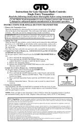
STEP BY STEP INSTALLATION<br />
STEP 7: Terminal Connections<br />
The radio receiver must be 12 VDC only (<strong>Elite</strong> Part # A 1099-12V). If you want to use safety<br />
or exit loops, you must use 12 VDC loop detectors only (<strong>Elite</strong> Part # A 23). The hook-ups<br />
for the radio receiver are as follows: Strike open wires go to 8 and 9 on terminal. Power<br />
supply goes to terminal 10 (positive +) and terminal 8 (negative -). Connections for other<br />
devices are shown below.<br />
HELP<br />
1 2 3<br />
4 5 6<br />
7 8 9<br />
0<br />
Phone<br />
Entry<br />
1 2 3 4 5 6 7 8 9 10<br />
Fire or<br />
Any Key<br />
Switch<br />
Card<br />
Reader<br />
Push<br />
Button<br />
Transmitters<br />
(<strong>Elite</strong> Part #A 3060)<br />
(<strong>Elite</strong> Part #A 3089)<br />
12 VDC Radio Receiver<br />
Terminal 8 = Grey Wire<br />
Terminal 8 = Black Wire<br />
Terminal 9 = Grey Wire<br />
Terminal 10= Red Wire<br />
External “Exit” Loop Detector<br />
External “Safety” Loop Detector<br />
Photo Electric Eye
STEP BY STEP INSTALLATION<br />
STEP 8: Adjusting <strong>Gate</strong> Travel Distance<br />
Adjustment is done by limit switches which are located on the Robo Slide chassis. By<br />
pressing the plate down and spinning the adjustment nuts, set your limit switches for open<br />
and close cycles.<br />
STEP 9: Timer<br />
If you want to use the automatic close for the gate system the timer switch should be put in<br />
the “ON” position. If you want to use the push open or push close command, the timer<br />
should be switched to the “OFF” position.<br />
Set Timer<br />
1 to 60 seconds<br />
TIMER UP<br />
ON<br />
60 0<br />
OFF<br />
TIMER UP<br />
PW<br />
ON<br />
60 0<br />
OFF<br />
PW<br />
Limit Switches<br />
CHARGING<br />
POWER<br />
CHECK<br />
FUSE<br />
BOARD<br />
POWER<br />
Each notch of the nut indicates an<br />
estimated 1 inch of gate travel<br />
OVERLOAD<br />
POWER<br />
CHARGE OK<br />
J2<br />
BATTERY LOW<br />
OPEN RELAY<br />
CLOSE RELAY<br />
OPEN TO RIGHT<br />
PW<br />
ON<br />
60 0<br />
OFF<br />
TIMER UP<br />
W1<br />
HEAVY<br />
GATE<br />
SYSTEM ON<br />
ALARM<br />
SENSOR<br />
DC OPERATOR v 5M<br />
MADE IN USA<br />
REVERSE<br />
SENSOR<br />
CENTRAL CONTROL<br />
FIRE<br />
DEPT<br />
STRIKE<br />
OPEN<br />
SAFETY<br />
LOOP<br />
EXIT<br />
LOOP<br />
RADIO<br />
REC
STEP BY STEP INSTALLATION<br />
STEP 10: Two-Way Adjustable Reversing Sensor<br />
There is a blue pot with a white screw adjustment on the upper portion of the control<br />
board marked “REVERSE SENSOR”. Do Not Touch Alarm Sensor blue pot.<br />
The level of sensitivity has to do with the weight of the gate and the condition of<br />
installation.<br />
Too sensitive = if the gate stops or reverses by itself.<br />
Not sensitive enough = if the gate hits an object and does not stop or reverse.<br />
Minimum<br />
Sensitivity<br />
Maximum<br />
Sensitivity<br />
HEAVY<br />
GATE<br />
SYSTEM ON<br />
ALARM<br />
SENSOR<br />
REVERSE<br />
SENSOR<br />
CHARGING<br />
POWER<br />
CHECK<br />
FUSE<br />
BOARD<br />
POWER<br />
OVERLOAD<br />
POWER<br />
CHARGE OK<br />
BATTERY LOW<br />
OPEN RELAY<br />
CLOSE RELAY<br />
OPEN TO RIGHT<br />
NOW YOUR INSTALLATION IS COMPLETE<br />
J2<br />
PW<br />
ON<br />
60 0<br />
OFF<br />
TIMER UP<br />
W1<br />
HEAVY<br />
GATE<br />
SYSTEM ON<br />
ALARM<br />
SENSOR<br />
DC OPERATOR v 5M<br />
MADE IN USA<br />
REVERSE<br />
SENSOR<br />
CENTRAL CONTROL<br />
There is an LED “HEAVY GATE” which will light up when the gate is heavier than normal for<br />
the operator. The operator will still function properly.<br />
FIRE<br />
DEPT<br />
STRIKE<br />
OPEN<br />
SAFETY<br />
LOOP<br />
EXIT<br />
LOOP<br />
RADIO<br />
REC
“OPTIONAL” INPUT BOARD<br />
The optional board allows extra control of the gate, is available only from <strong>Elite</strong> Access<br />
Systems. Installation is simple; just clip the optional board to the J2 slot on the top of the<br />
control board. Below lists the function of each pin.<br />
1<br />
3<br />
5<br />
1 & 2<br />
3 & 4<br />
5 & 6<br />
7 & 8<br />
9 &10<br />
11 & 4<br />
12 & 7<br />
13 & 14<br />
15 & 16<br />
7<br />
9<br />
Open Switch<br />
Stop Switch (Cut W1 Jumper at Bottom of Board)<br />
Timer Close Output from Master to Slave<br />
Timer Input from Slave to Master (Close Command)<br />
Vandalism Alarm Output (Not Burglar Alarm) - 12 VDC<br />
Emergency Open (Direct Command from Battery to Motor)<br />
Emergency Close (Direct Command from Battery to Motor)<br />
Magnetic Lock - Dry Contact Relay (Com NC)<br />
Center Loop Option (For Swing <strong>Gate</strong> Operators Only)<br />
11<br />
2 4 6 8 10 12 14<br />
16-Pin Plug<br />
CHARGING<br />
POWER<br />
13<br />
CHECK<br />
FUSE<br />
15<br />
16<br />
BOARD<br />
POWER<br />
OVERLOAD<br />
POWER<br />
CHARGE OK<br />
BATTERY LOW<br />
OPEN RELAY<br />
CLOSE RELAY<br />
J2<br />
W1<br />
HEAVY<br />
GATE<br />
SYSTEM ON<br />
ALARM<br />
SENSOR<br />
DC OPERATOR v 5M<br />
MADE IN USA<br />
Use a<br />
Normally<br />
Closed<br />
Contact<br />
REVERSE<br />
SENSOR<br />
CENTRAL CONTROL<br />
FIRE<br />
DEPT
MASTER AND SLAVE WITH TIMER<br />
To use the master/slave option with Robo Slide, you must purchase the Optional Input<br />
Board (<strong>Elite</strong> Part # Q203) and connect it to the J2 slot. Refer to Optional Input Board<br />
Caution: 18 VAC plug-in transformer, per gate operator required<br />
Master Slave<br />
1<br />
2<br />
3<br />
4<br />
5<br />
6<br />
Master J2 Plug<br />
Set Timer<br />
0 to 60 seconds<br />
7 9 11 13 15<br />
8 10 12 14 16<br />
4 Low Voltage Wires Connect <strong>Gate</strong> Operators Together<br />
1. Make master/slave J2 plug connections as shown above<br />
2. Turn timers on BOTH control boards to the “ON” position<br />
3. Use MASTER timer ONLY for the auto close time adjustment (0 to 60 sec)<br />
4. Turn the SLAVE timer adjustment all the way Counterclockwise<br />
Master Timer “ON”<br />
TIMER TIMER UP<br />
ON ON<br />
60 60 0<br />
OFF<br />
Master Pin 5 to Slave Pin 7<br />
Master Pin 1 to Slave Pin 1<br />
Master Pin 6 to Slave Pin 8<br />
Master Pin 2 to Slave Pin 2<br />
PW<br />
1<br />
Slave Timer “ON”<br />
TIMER TIMER UP<br />
ON ON<br />
OFF<br />
2<br />
PW<br />
60 0<br />
Maximum<br />
Counterclockwise<br />
Setting<br />
3<br />
4<br />
5<br />
6<br />
7<br />
8<br />
9<br />
10<br />
11<br />
12<br />
13<br />
14<br />
15<br />
16<br />
Slave J2 Plug
MASTER AND SLAVE WITHOUT TIMER<br />
To use the master/slave option with Robo Slide, you must purchase the Optional Input<br />
Board (<strong>Elite</strong> Part # Q203) and connect it to the J2 slot. Refer to Optional Input Board<br />
Caution: 18 VAC plug-in transformer, per gate operator required<br />
Master Slave<br />
1<br />
2<br />
3 5 7 9 11 13 15<br />
4 6 8 10 12 14 16<br />
Master J2 Plug<br />
2 Low Voltage Wires Connect <strong>Gate</strong> Operators Together<br />
Master Pin 1 to Slave Pin 1<br />
Master Pin 2 to Slave Pin 2<br />
1. Make master/slave J2 plug connections as shown above<br />
2. Turn timers on BOTH control boards to the “OFF” position<br />
Master Timer “OFF”<br />
TIMER TIMER UP<br />
ON<br />
60 0<br />
OFF OFF<br />
PW<br />
1<br />
2<br />
3<br />
4<br />
5 7<br />
6 8<br />
Slave Timer “OFF”<br />
TIMER TIMER UP<br />
ON<br />
60 0<br />
OFF OFF<br />
PW<br />
9<br />
10<br />
11<br />
12<br />
13<br />
14<br />
15<br />
16<br />
Slave J2 Plug
CONTROL BOARD FUNCTIONS<br />
1 Power on LED<br />
2 Charge on LED<br />
3 Low battery indicator LED<br />
4 Heavy gate indicator LED<br />
5 Open Relay LED<br />
6 Close Relay LED<br />
7 System on, Reversing sensor and Alarm sensor<br />
8 Alarm sensor LED<br />
9 Reversing sensor LED (Rebounder)<br />
10 Central control LED<br />
11 Fire department or key switch LED<br />
12 Strike open LED<br />
13 Safety loop or photocell LED<br />
14 Exit loop LED<br />
20<br />
26<br />
1<br />
2<br />
3<br />
5<br />
6<br />
25<br />
CHARGING<br />
POWER<br />
CHECK<br />
FUSE<br />
BOARD<br />
POWER<br />
19<br />
OVERLOAD<br />
POWER<br />
CHARGE OK<br />
BATTERY LOW<br />
OPEN RELAY<br />
CLOSE RELAY<br />
OPEN TO RIGHT<br />
J2<br />
22<br />
TIMER UP<br />
ON<br />
60 0<br />
OFF<br />
15 Radio receiver LED<br />
16 Timer power LED<br />
17 Timer-Up indicator<br />
18 J2 alternate optional output<br />
19 Movement direction sockets<br />
20 Replace fuse indicator<br />
21 Spike suppressor<br />
22 Jumper for stop button<br />
23 Optional Input board<br />
24 Plug in power - 18 VAC or solar panel<br />
and terminal block connector<br />
25 Breaker reset<br />
26 Overload LED<br />
PW<br />
W1<br />
HEAVY<br />
GATE<br />
SYSTEM ON<br />
ALARM<br />
SENSOR<br />
DC OPERATOR v 5M<br />
MADE IN USA<br />
REVERSE<br />
SENSOR<br />
CENTRAL CONTROL<br />
FIRE<br />
DEPT<br />
STRIKE<br />
OPEN<br />
SAFETY<br />
LOOP<br />
EXIT<br />
LOOP<br />
RADIO<br />
REC<br />
23<br />
18<br />
7<br />
8<br />
9<br />
4<br />
10<br />
11<br />
12<br />
13<br />
14<br />
15<br />
16<br />
17<br />
21<br />
24
1<br />
2<br />
3<br />
4<br />
5<br />
6<br />
7<br />
8<br />
Power at all times when<br />
there is one or more<br />
power sources<br />
ie: Battery, 18 VAC or solar<br />
Charger OK on when there<br />
is any charging power<br />
ie: 18 VAC - solar<br />
Battery Low<br />
normally off - it will<br />
indicate low battery<br />
Heavy <strong>Gate</strong><br />
will work only when the<br />
gate is in motion<br />
System On<br />
will work only when the<br />
gate is in motion<br />
Alarm Sensor<br />
when LED goes on you<br />
will hear a beep sound<br />
for about 20 seconds<br />
LED DESCRIPTION<br />
LED Description LED On LED Off<br />
Power source OK and<br />
board power fuse OK<br />
Transformer or solar OK<br />
and charging power fuse OK<br />
Flashing LED - Battery is<br />
less than required limit<br />
needs to be recharged<br />
1. Excess usage<br />
2. Bad charging system<br />
3. Under rate solar panel<br />
4. Bad battery<br />
5. Bad battery connection<br />
1. <strong>Gate</strong> is too heavy<br />
2. Bad wheels<br />
3. Bad rollers<br />
4. Chain is too tight<br />
5. Steep slope on open or<br />
close cycle<br />
6. Low battery<br />
1. No power source at all<br />
If dimmed down<br />
1. Bad board power fuse<br />
1. No Transformer or Solar<br />
If dimmed down<br />
1. Bad Charging power fuse<br />
Battery OK<br />
Battery voltage is over<br />
minimum required limit<br />
<strong>Gate</strong> weight and<br />
condition are OK<br />
Open Relay Open relay is energized Open relay is not energized<br />
Close Relay Close relay is energized Close relay is not energized<br />
Detecting motor current<br />
1. Hearing beep sound<br />
means overload<br />
2. <strong>Gate</strong> is too heavy<br />
3. Broken wheel<br />
4. <strong>Gate</strong> off track<br />
5. Unwanted object has<br />
physically stopped gate<br />
1. Motor stop<br />
2. No motor current detected<br />
System is OK<br />
Note: Circled red numbers indicates location on control board. Refer to Control Board Functions
LED DESCRIPTION - CONTINUED<br />
LED Description LED On LED Off<br />
9 Reversing Sensor Sensor is detecting obstruction No obstruction is detected<br />
10 Central Control<br />
• Fire Department 1 & 2<br />
• Strike Open 3 & 4<br />
Not receiving any command<br />
• Safety Loop 5 & 6<br />
• Exit Loop 7 & 8<br />
• Radio Receiver 8 & 9<br />
11 Fire Dept<br />
12 Strike Open<br />
13 Safety Loop<br />
14 Exit Loop<br />
15 Radio Rec<br />
Acknowledgement of<br />
receiving open command<br />
from one of the terminals<br />
Receiving signal at terminal<br />
block 1 & 2<br />
Receiving signal at terminal<br />
block 3 & 4<br />
Receiving signal at terminal<br />
block 5 & 6<br />
Receiving signal at terminal<br />
block 7 & 8<br />
Receiving signal at terminal<br />
block 8 & 9<br />
17 Timer UP Output signal to close relay<br />
Not receiving signal at<br />
terminal block 1 & 2<br />
Not receiving signal at<br />
terminal block 3 & 4<br />
Not receiving signal at<br />
terminal block 5 & 6<br />
Not receiving signal at<br />
terminal block 7 & 8<br />
Not receiving signal at<br />
terminal block 8 & 9<br />
16 Timer PW Timer power is on Timer is not on<br />
Not receiving signal to<br />
close relay<br />
Note: Circled red numbers indicates location on control board. Refer to Control Board Functions
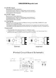
TROUBLESHOOTING<br />
How to Reset the Breaker<br />
If all electronic sensors fail or are not adjusted properly due to heavy gates, off-track gate,<br />
or obstructed gate path, the breaker will kick-out. Reset the breaker by pressing the reset<br />
button located on the bottom left corner of the control board.<br />
CAUTION<br />
How to Check the Fuses<br />
CHARGING<br />
POWER<br />
CHECK<br />
FUSE<br />
BOARD<br />
POWER<br />
OVERLOAD<br />
POWER<br />
CHARGE OK<br />
BATTERY LOW<br />
OPEN RELAY<br />
CLOSE RELAY<br />
J2<br />
OPEN TO RIGHT<br />
If the gate is not moving in any direction be sure to check all of the LED displays on the<br />
control board. If the board power or charging power LEDs are “ON”, change the<br />
corresponding fuse on the top left corner of the board.<br />
CAUTION<br />
Always disconnect the battery before<br />
resetting the breaker or injury could<br />
occur as the gate starts.<br />
Replace fuse with<br />
1.5A - 250V fuse<br />
Robo Fuse<br />
(<strong>Elite</strong> Part # Q162)<br />
The breaker reset is located at<br />
the bottom left corner of the<br />
control board as shown<br />
HEAVY<br />
GATE<br />
DC OPE<br />
MAD
The <strong>Gate</strong> Will Not Close!<br />
The <strong>Gate</strong> Will Not Open!<br />
TROUBLESHOOTING<br />
PW<br />
0<br />
PW<br />
0<br />
DC OPERATOR v 5M<br />
MADE IN USA<br />
CENTRAL CONTROL<br />
DC OPERATOR v 5M<br />
MADE IN USA<br />
FIRE<br />
DEPT<br />
STRIKE<br />
OPEN<br />
SAFETY<br />
LOOP<br />
EXIT<br />
LOOP<br />
RADIO<br />
REC<br />
CENTRAL CONTROL<br />
FIRE<br />
DEPT<br />
STRIKE<br />
OPEN<br />
SAFETY<br />
LOOP<br />
EXIT<br />
LOOP<br />
RADIO<br />
REC<br />
For further information, contact your local dealer.<br />
Symptom: The radio receiver LED on the control board<br />
remains “ON” when using the remote control.<br />
Possible Solutions: Stuck remote control button.<br />
The radio receiver has malfunctioned in the “ON”<br />
position.<br />
Symptom: The radio receiver LED on the control board<br />
remains “OFF” when using the remote control.<br />
Possible Solutions: Dead battery in the remote<br />
control. Remote control code switches are different from<br />
radio receiver code switches. The radio receiver has<br />
malfunctioned in the “OFF” position.
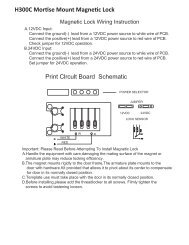
TROUBLESHOOTING and PARTS LIST<br />
If you hear a “BEEP” sound, the gate is too heavy. If not check below.<br />
ALARM<br />
SENSOR<br />
ALARM<br />
SENSOR<br />
1 Debris is on the gate's track such as<br />
mud, rocks dirt, etc.<br />
3<br />
Robo Slide Parts List<br />
Robo Slide Conversion Kit<br />
Q211 - Limit/Motor Harness<br />
Q218 - Terminal Harness<br />
Q204<br />
Q206 - Control Board<br />
Battery Harness<br />
A BT 12 - 12 VDC, 7 amp. Battery with Harness<br />
A H-110 - <strong>Gate</strong> Chain #41 (10 ft) (20 ft included)<br />
A H-111 - <strong>Gate</strong> Chain #40 (10 ft) Optional<br />
A H-113 - Master Link<br />
A H-125 - Master Link<br />
Q003 - Chain Bolt<br />
Q004 - Chain Bracket<br />
Q006 - PC Board Nuts (1 Set)<br />
Q029 - Limit Switch<br />
Q032 - Limit Switch Adjustment Nut<br />
Q101 - Limit Switch Bearing Holder<br />
Q123 - Motor - DC - 12V<br />
ALARM<br />
SENSOR<br />
ALARM<br />
SENSOR<br />
2<br />
The gate is hitting a wall or a car.<br />
The gate has one or more broken wheels. 4 A car has hit the gate and<br />
the gate is off the track.<br />
After fixing the problem, the Robo Slide will automatically reset itself.<br />
Q124 - Chassis<br />
Q129 - Idler Sprocket with Bolt/Nut<br />
Q131 - Limit Switch Drive Sprocket<br />
Q132 - Limit Switch Sprocket<br />
Q133 - Drive Sprocket<br />
Q135 - Limit Switch Bolt (Shaft)<br />
Q137 - Limit Switch Box<br />
Q156 - 1/2 Inch Collar<br />
Q162 - Fuse<br />
Q180 - 1 inch Diameter Coupling<br />
Q203 - Option Board with Harness<br />
Q206 - Control Board<br />
Q211 - Limit/Motor Harness<br />
Q212 - Gear Reducer 40 - 30:1<br />
Q218 - Terminal Harness<br />
Q241 - Cover, Polyethylene Plastic<br />
Multiple Parts “Q” Number<br />
21
*Q003<br />
A H-110<br />
#41<br />
Q241<br />
Q133<br />
A BT 12<br />
*Q129<br />
A H-113 A H-125<br />
*Q004<br />
ROBO SLIDE PARTS<br />
A H-111<br />
#40<br />
Q124<br />
Q162<br />
Q006<br />
CHECK<br />
FUSE<br />
CHARGING BOARD<br />
POWER<br />
POWER<br />
OVERLOAD<br />
POWER<br />
J2<br />
CHARGE OK<br />
BATTERY LOW<br />
OPEN RELAY<br />
CLOSE RELAY<br />
OPEN TO RIGHT<br />
Q203<br />
PW<br />
ON<br />
60 0<br />
Q132<br />
Q206<br />
Q211<br />
Q211<br />
Q131<br />
Q134<br />
Q137<br />
Note: *Sold Individually, 2 Shown.<br />
For part names, refer to parts list<br />
TIMER UP<br />
OFF<br />
HEAVY<br />
GATE<br />
W1<br />
SYSTEM ON<br />
ALARM REVERSE<br />
SENSOR SENSOR<br />
DC OPERATOR v 5M<br />
MADE IN USA<br />
CENTRAL CONTROL<br />
FIRE<br />
DEPT<br />
STRIKE<br />
OPEN<br />
SAFETY<br />
LOOP<br />
EXIT<br />
LOOP<br />
RADIO<br />
REC<br />
Q156<br />
Q206<br />
Q218<br />
Q218<br />
*Q101<br />
CHECK<br />
FUSE<br />
CHARGING BOARD<br />
POWER<br />
POWER<br />
OVERLOAD<br />
POWER<br />
J2<br />
CHARGE OK<br />
BATTERY LOW<br />
OPEN RELAY<br />
CLOSE RELAY<br />
OPEN TO RIGHT<br />
PW<br />
ON<br />
60 0<br />
TIMER UP<br />
OFF<br />
HEAVY<br />
GATE<br />
W1<br />
SYSTEM ON<br />
ALARM REVERSE<br />
SENSOR SENSOR<br />
DC OPERATOR v 5M<br />
MADE IN USA<br />
CENTRAL CONTROL<br />
FIRE<br />
DEPT<br />
STRIKE<br />
OPEN<br />
SAFETY<br />
LOOP<br />
EXIT<br />
LOOP<br />
RADIO<br />
REC<br />
Battery<br />
Harness<br />
Q204<br />
Conversion Kit<br />
*Q029<br />
Q123<br />
Q212<br />
*Q032<br />
Q180<br />
Q135