Residual Strength and Fatigue Lifetime of ... - Solid Mechanics
Residual Strength and Fatigue Lifetime of ... - Solid Mechanics Residual Strength and Fatigue Lifetime of ... - Solid Mechanics
Figure 1.3: Fracture modes, from Berggreen (2005). A stress singularity at the crack tip for a 2D problem, introduced by each mode of loading, can be defined in a polar coordinate system as where is Kronecker’s delta, T the non-singular stress parallel to the crack surface. r and are radius and angle in a polar coordinate system with origin at the crack tip. and are two functions defining the shape of the stress field, see Figure 1.4. KI and KII are the mode I and II stress intensity factors. If the definition of three crack tip loading modes is applied to the stress field, then the pure mode I stress field will be symmetric with respect to the crack line with and for =0, and the pure mode II is anti-symmetric with and for =0. Consequently, KI and KII can be defined as (1.4) Figure 1.4: Homogeneous near-crack tip definitions. The theory described above is known as homogeneous linear elastic fracture mechanics, which is applicable to the fracture of homogeneous solids where the plasticity at the crack tip is very small compared to the crack geometry. 6 r (1.3)
1.4 Linear Elastic Fracture Mechanics in Material Interfaces Linear elastic fracture mechanics (LEFM) addresses the fracture of solids in which the size of the zone dominated by non-linear inelastic deformations close to the crack tip is small compared to the crack length. When a crack propagates in homogeneous solids it mostly occurs in opening mode I loading. Even if there is an initial mixed-mode loading at the crack tip, the crack will eventually kink into a path with pure mode I loading. However, in an interface crack between two dissimilar materials this is not the case and the crack tip loading is a mixed-mode loading even if the global load is pure mode I. This is to due asymmetries of moduli and Poisson’s ratios along the interface, where both shear and normal stresses exist in the crack front (He and Hutchinson, 1989). A strong dependency of the fracture toughness and mode-mixity has been observed in different experimental investigations, e.g. Liechti and Chai (1992), making the mode-mixity phase angle an important parameter for the characterisation of interface cracks. Figure 1.5: Interface crack geometry. A general interface crack problem assumes that a crack is located between two orthotropic elastic materials denoted as #1 and #2, as shown in Figure 1.5. Two materials are joined along a straight interface and the crack tip is located at x=0. The displacement and stress fields close to the crack tip can be described according to Suo (1989): where y and x are the opening and sliding relative displacements of the crack flanks, and are normal and shear stresses. K is the complex stress intensity factor defined as (1.7) 7 (1.5) (1.6)
- Page 1: Residual Strength and Fatigue Lifet
- Page 4 and 5: Published in Denmark by Technical U
- Page 6 and 7: This page is intentionally left bla
- Page 8 and 9: method to accelerate the simulation
- Page 10 and 11: Synopsis Sandwich kompositter er i
- Page 12 and 13: This page is intentionally left bla
- Page 14 and 15: Contents Preface Executive Summary
- Page 16 and 17: 5 Face/core Interface Fatigue Crack
- Page 18 and 19: This page is intentionally left bla
- Page 20 and 21: H11 bimaterial constant H22 bimater
- Page 22 and 23: This page is intentionally left bla
- Page 24 and 25: These peculiar damage modes often r
- Page 26 and 27: 1.2 Overview of the Thesis In this
- Page 30 and 31: In Equations (1.5) and (1.6) H11, H
- Page 32 and 33: Figure 1.6: Schematic illustration
- Page 34 and 35: The compact tension specimen (CT) i
- Page 36 and 37: A Figure 1.10: CSB, DCB, TSD, DCB-U
- Page 38 and 39: Chapter 2 Buckling Driven Face/Core
- Page 40 and 41: (DIC) measurement system (ARAMIS 2M
- Page 42 and 43: corresponds to the onset of debond
- Page 44 and 45: Figure 2.7: Crack kinking into the
- Page 46 and 47: (2.2) where and for plane str
- Page 48 and 49: A modified version of the tilted sa
- Page 50 and 51: previous observations of crack path
- Page 52 and 53: of contact elements (CONTACT173 and
- Page 54 and 55: the debond opening initially increa
- Page 56 and 57: Table 2.4: Instability loads determ
- Page 58 and 59: G (J/m2) 600 400 200 0 H100 IMP=0.1
- Page 60 and 61: This page is intentionally left bla
- Page 62 and 63: Hayman (2007) has described a damag
- Page 64 and 65: Table 3.1: Panel test specimens. La
- Page 66 and 67: sheet and the core thickness, respe
- Page 68 and 69: Load (N) 250 200 150 100 50 0 H130
- Page 70 and 71: Table 3.4: Parameters in the face/c
- Page 72 and 73: was used to monitor 3D surface disp
- Page 74 and 75: arising due to the junction between
- Page 76 and 77: (a) Debonded face sheet Figure 3.16
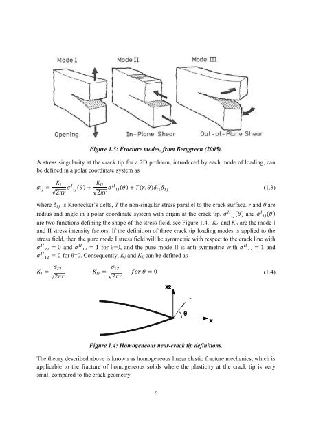
Figure 1.3: Fracture modes, from Berggreen (2005).<br />
A stress singularity at the crack tip for a 2D problem, introduced by each mode <strong>of</strong> loading, can<br />
be defined in a polar coordinate system as<br />
<br />
<br />
<br />
where is Kronecker’s delta, T the non-singular stress parallel to the crack surface. r <strong>and</strong> are<br />
radius <strong>and</strong> angle in a polar coordinate system with origin at the crack tip. <strong>and</strong> <br />
are two functions defining the shape <strong>of</strong> the stress field, see Figure 1.4. KI <strong>and</strong> KII are the mode I<br />
<strong>and</strong> II stress intensity factors. If the definition <strong>of</strong> three crack tip loading modes is applied to the<br />
stress field, then the pure mode I stress field will be symmetric with respect to the crack line with<br />
<strong>and</strong> for =0, <strong>and</strong> the pure mode II is anti-symmetric with <strong>and</strong><br />
for =0. Consequently, KI <strong>and</strong> KII can be defined as<br />
<br />
<br />
(1.4)<br />
Figure 1.4: Homogeneous near-crack tip definitions.<br />
The theory described above is known as homogeneous linear elastic fracture mechanics, which is<br />
applicable to the fracture <strong>of</strong> homogeneous solids where the plasticity at the crack tip is very<br />
small compared to the crack geometry.<br />
6<br />
r<br />
(1.3)


