

Rasmus ÿstergaard forside 100%.indd - Solid Mechanics
Rasmus ÿstergaard forside 100%.indd - Solid Mechanics
Rasmus ÿstergaard forside 100%.indd - Solid Mechanics

Create successful ePaper yourself
Turn your PDF publications into a flip-book with our unique Google optimized e-Paper software.
304 R.C. Østergaard, B.F. Sørensen<br />
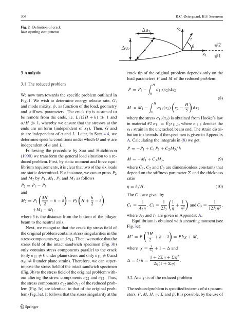
Fig. 2 Definition of crack<br />
face opening components<br />
3 Analysis<br />
3.1 The reduced problem<br />
We now turn towards the specific problem outlined in<br />
Fig. 1. We wish to determine energy release rate, G,<br />
and mode mixity, ψ, as function of the load, geometry<br />
and stiffness parameters. The crack-tip is assumed to<br />
be remote from the ends, i.e. L/(2H + h) ≫ 1 and<br />
a/H ≫ 1, whereby we ensure that the stresses at the<br />
ends are uniform (independent of x1). Then, G and<br />
ψ are independent of a and L. Later, in Sect. 4.4, we<br />
determine specific conditions under which G and ψ are<br />
independent of a and L.<br />
Following the procedure by Suo and Hutchinson<br />
(1990) we transform the general load situation to a reduced<br />
problem. First, by static moment and force equilibrium<br />
requirements, it is clear that two of the six loads<br />
are static determined. For instance, we can express P2<br />
and M2 by P1, M1, P3 and M3 as follows<br />
P2 = P1 − P3<br />
and<br />
<br />
3H<br />
M2 = P1 − h − δ − P3 H +<br />
2 h<br />
<br />
− δ<br />
2<br />
+M1 − M3,<br />
where δ is the distance from the bottom of the bilayer<br />
beam to the neutral axis.<br />
Next, we recognize that the crack tip stress field of<br />
the original problem contains stress singularities in the<br />
stress components σ22 and σ12. Then, we notice that the<br />
stress field of the intact sandwich specimen (Fig. 3b)<br />
only contains stress components parallel to the crack<br />
(only σ11 = 0 under plane stress and only σ11 = 0 and<br />
σ33 = 0 under plane strain). Therefore, we can superimpose<br />
the stress field of the intact sandwich specimen<br />
(Fig. 3b) to the stress field of the original problem without<br />
altering the stress components σ22 and σ12. Thus,<br />
the stress components σ22 and σ12 of the reduced problem<br />
(Fig. 3c) are identical to that of the original problem<br />
(Fig. 3a). It follows that the stress singularity at the<br />
123<br />
Δu2<br />
Δu1<br />
x2<br />
r<br />
θ<br />
x1<br />
#2<br />
#1<br />
crack tip of the original problem depends only on the<br />
load parameters P and M of the reduced problem:<br />
P = P1 −<br />
H<br />
0<br />
σ11(x2)dx2<br />
H <br />
M = M1 − σ11(x2) x2 −<br />
0<br />
H<br />
<br />
dx2<br />
2<br />
(8)<br />
where the stress σ11(x2) is obtained from Hooke’s law<br />
in material #2 σ11 = Ē2ɛ11,3, where ɛ11,3 denotes the<br />
ɛ11 strain in the uncracked beam end. The strain distribution<br />
in the ends of the specimen is given in Appendix<br />
A. Calculating the integrals in (8) we get<br />
P =−P1 + C1 P3 + C2M3/h<br />
M =−M1 + C3M3, (9)<br />
where C1, C2 and C3 are dimensionless constants that<br />
depend on the stiffness parameter and the thickness<br />
ratio<br />
η = h/H. (10)<br />
The C’s are given by<br />
C1 = 1<br />
A3η , C2 = 1<br />
2I3<br />
<br />
1 1<br />
+<br />
η η2 <br />
and C3 =<br />
1<br />
,<br />
12I3η3 where A3 and I3 are given in Appendix A.<br />
Equilibrium is obtained with a reacting moment (see<br />
Fig. 3c):<br />
M ∗ <br />
3H<br />
= P + h − δ = Phχ + M,<br />
2<br />
where χ = 3<br />
2η + 1 − and<br />
= δ/h =<br />
1 + 2η + η2<br />
.<br />
2η(1 + η)<br />
3.2 Analysis of the reduced problem<br />
The reduced problem is specified in terms of six parameters,<br />
P, M, H, η, and β. It is possible, by the use of


