

Rasmus ÿstergaard forside 100%.indd - Solid Mechanics
Rasmus ÿstergaard forside 100%.indd - Solid Mechanics
Rasmus ÿstergaard forside 100%.indd - Solid Mechanics

You also want an ePaper? Increase the reach of your titles
YUMPU automatically turns print PDFs into web optimized ePapers that Google loves.
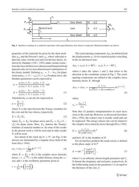
Interface crack in sandwich specimen 303<br />
P1<br />
P2<br />
M1<br />
M2<br />
Neutral axis<br />
δ<br />
a<br />
x2<br />
x1<br />
L<br />
face sheet<br />
H<br />
core h #1<br />
face sheet<br />
Fig. 1 Interface cracking of a sandwich specimen with equal thickness face sheets is analyzed. Material numbers are shown<br />
properties of the materials be given by the shear modulus<br />
μm and the Poisson’s ratio νm, where subscript m<br />
takes the value 1 for the core and 2 for the face sheets. As<br />
shown by Dundurs (1967, 1969) under certain restrictionsthestressfieldinatwo-dimensionalbimaterialbody<br />
depends only on two non-dimensional combinations of<br />
the elastic moduli. Defining κm = 3 − 4νm for plane<br />
strain and κm = (3 − νm)/(1 + νm) for plane stress, the<br />
Dundurs parameters can be expressed as<br />
α = μ1(κ2 + 1) − μ2(κ1 + 1)<br />
μ1(κ2 + 1) + μ2(κ1 + 1) and<br />
β = μ1(κ2 − 1) − μ2(κ1 − 1)<br />
. (1)<br />
μ1(κ2 + 1) + μ2(κ1 + 1)<br />
Alternatively, α can also be expressed as<br />
− 1<br />
α = , (2)<br />
+ 1<br />
where is the ratio between the Young’s modulus for<br />
the core and the face sheets, respectively<br />
= Ē1/Ē2, (3)<br />
where Ēm = Em for plane stress and Ēm = Em/(1 −<br />
ν2 m ) for plane strain. Here, Em denotes the Young’s<br />
modulus of material number m. In some of the results<br />
in the present work α will be used and in other results<br />
will be used.<br />
Just ahead of the crack tip (θ = 0◦ , see Fig. 2) the<br />
stresses are dominated by a singular stress field of the<br />
form (Rice 1988):<br />
σ22 + iσ12 = 1<br />
√ 2π Kr iɛ−1/2 , (4)<br />
where K = K1 + iK2 is the complex stress intensity<br />
factor, i = √ −1, r is the radial distance along the x1-<br />
axis and ɛ is the oscillatory parameter given as<br />
ɛ = 1<br />
2π ln<br />
1 − β<br />
1 + β<br />
<br />
.<br />
H<br />
#2<br />
#2<br />
M3<br />
The crack opening components un are defined from<br />
the displacements un of two material points coinciding<br />
in the un-deformed state<br />
P3<br />
un = un(r,θ = 90 ◦ ) − un(r,θ =−90 ◦ ),<br />
where n takes the values 1 and 2, that refers to the<br />
direction in the coordinate system in Fig. 2. The crack<br />
opening components are related to the complex stress<br />
intensity factor, K , through<br />
u2 + iu1 =<br />
where<br />
c1 + c2<br />
2 √ 2π(1 + 2iɛ)cosh(πɛ) Kriɛ+1/2 ,<br />
(5)<br />
cm = κm + 1<br />
.<br />
μm<br />
Note that (5) predicts interpenetration of crack faces<br />
close to the crack tip. However, as discussed elsewhere<br />
(Rice 1988), the contact zone is usually small and can<br />
be neglected. The energy release rate can be related to<br />
the complex stress intensity factor through (Rice 1988):<br />
c1 + c2<br />
G =<br />
16 cosh2 |K |2<br />
(6)<br />
(πɛ)<br />
and here |K | is the modulus of K .<br />
For an interface problem the mode mixity is defined<br />
as the phase angle of Kliɛ ψ = tan −1<br />
<br />
ℑ(Kliɛ )<br />
ℜ(Kliɛ <br />
, (7)<br />
)<br />
where l is an arbitrary chosen length parameter and ℑ,<br />
ℜ denote the imaginary and real parts, respectively. In<br />
the forthcoming analysis the parameter l is set equal to<br />
the thickness of the core, h.<br />
123


