Rasmus ÿstergaard forside 100%.indd - Solid Mechanics
Rasmus ÿstergaard forside 100%.indd - Solid Mechanics Rasmus ÿstergaard forside 100%.indd - Solid Mechanics
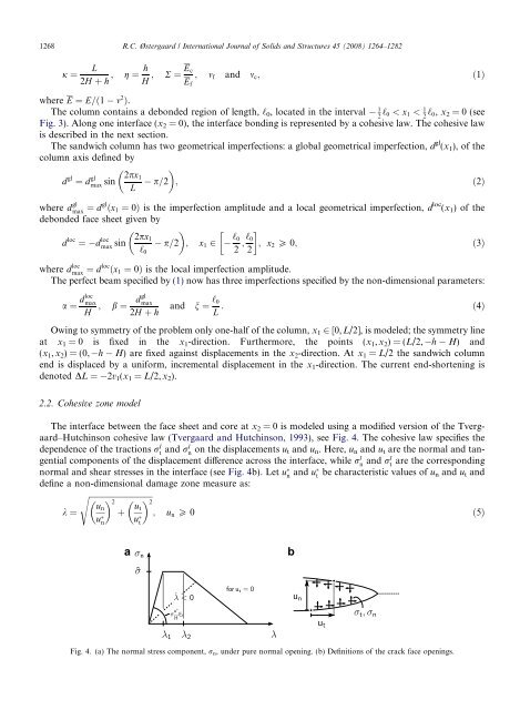
1268 R.C. Østergaard / International Journal of Solids and Structures 45 (2008) 1264–1282 j ¼ L h Ec ; g ¼ ; R ¼ ; mf and mc; ð1Þ 2H þ h H Ef where E ¼ E=ð1 m2Þ. 1 The column contains a debonded region of length, ‘0, located in the interval 2 ‘0 < x1 < 1 2 ‘0, x2 = 0 (see Fig. 3). Along one interface (x2 = 0), the interface bonding is represented by a cohesive law. The cohesive law is described in the next section. The sandwich column has two geometrical imperfections: a global geometrical imperfection, d gl (x1), of the column axis defined by d gl ¼ d gl 2px1 max sin L p=2 ; ð2Þ where d gl max ¼ dgl ðx1 ¼ 0Þ is the imperfection amplitude and a local geometrical imperfection, d loc (x1) ofthe debonded face sheet given by d loc ¼ d loc 2px1 max sin ‘0 p=2 ; x1 2 ‘0 ‘0 ; 2 2 ; x2 P 0; ð3Þ where d loc max ¼ dloc ðx1 ¼ 0Þ is the local imperfection amplitude. The perfect beam specified by (1) now has three imperfections specified by the non-dimensional parameters: ; b ¼ dgl max 2H þ h and n ¼ ‘0 : ð4Þ L a ¼ dloc max H Owing to symmetry of the problem only one-half of the column, x1 2 [0, L/2], is modeled; the symmetry line at x1 = 0 is fixed in the x1-direction. Furthermore, the points (x1,x2)=(L/2, h H) and (x1,x2) = (0, h H) are fixed against displacements in the x2-direction. At x1 = L/2 the sandwich column end is displaced by a uniform, incremental displacement in the x1-direction. The current end-shortening is denoted DL = 2v1(x1 = L/2,x2). 2.2. Cohesive zone model The interface between the face sheet and core at x2 = 0 is modeled using a modified version of the Tvergaard–Hutchinson cohesive law (Tvergaard and Hutchinson, 1993), see Fig. 4. The cohesive law specifies the dependence of the tractions rI t and rI n on the displacements ut and un. Here, un and ut are the normal and tangential components of the displacement difference across the interface, while rI n and rI t are the corresponding normal and shear stresses in the interface (see Fig. 4b). Let un and ut be characteristic values of un and ut and define a non-dimensional damage zone measure as: sffiffiffiffiffiffiffiffiffiffiffiffiffiffiffiffiffiffiffiffiffiffiffiffiffiffiffiffiffiffiffiffi k ¼ un un 2 þ ut u t 2 ; un P 0 ð5Þ Fig. 4. (a) The normal stress component, rn, under pure normal opening. (b) Definitions of the crack face openings.
such that the tractions rn and rt drop to zero at k = 1. Then, as k is monotonically increasing the tractions in the interface are given by (Tvergaard, 1990): r I n ¼ un=un k rðkÞ and rI t ¼ ut=u t k un ut rðkÞ; ð6Þ where r(k) denotes the interface normal stress under pure normal separation (ut 0). r(k) is given by a trapezoidal shape that starts at r =0atk = 0 and increases linearly to a peak value ^r at k = k1. This stress level is retained until k = k2 where after it decreases linearly to zero. For 0 < k < 1 this can be written as: ^r rðkÞ ¼ k 8 >< for 0 < k 6 k1 k1 ^r for k1 < k 6 k2 ; for >: k 1 ^r for k2 < k < 1 k2 1 _ k P 0andk¼kmax; ð7Þ where _ k ¼ ok oun _un þ ok out _ut and _un and _ut are the increments of un and ut. kmax is the largest k attained through the loading history. k = k(x1) constitutes a measure of the state of the interface at x1: For k < k1 the interface is undamaged. For k1 6 k < 1 the interface is damaged and for k P 1 the interface has fractured. In order to model non-monotonic opening, a linear unloading (see Fig. 4a) is used to represent the partly damaged interface: r I un rðkmaxÞ n ¼ un kmax and r I ut un t ¼ ut ut rðkmaxÞ kmax ; k < kmax or _ k < 0: ð8Þ To resist face sheet penetration of the core (un < 0) we use a contact law where the normal stress is calculated according to (6)–(8), but with (6a) and (8a) replaced by r I n ¼ knun; un < 0; ð9Þ where kn is a stiffness constant. The shear stresses are still given by (6) but with the dimensionless opening parameter defined as k ¼ ut=u t ; un < 0: ð10Þ In the present study we use: kn ¼ ^rn : ð11Þ k1un The parameters governing the interface law are ^r, un , ut together with the shape factors k1 and k2. The work of separation per unit area of interface (fracture toughness), C, is given by C ¼ 1 2 ^run½1 k1 þ k2Š: ð12Þ Equivalently the parameters can be taken as C, un , ut , k1 and k2. In the present study we use un ¼ ut ¼ u .In terms of non-dimensional constants the cohesive law is then specified by C EfH ; R.C. Østergaard / International Journal of Solids and Structures 45 (2008) 1264–1282 1269 u H ; k1 and k2: ð13Þ The shape of this cohesive law, (7), was originally suggested to represent the fracture mechanism of ductile metals (Tvergaard and Hutchinson, 1992). Various other cohesive laws exist. For mixed mode interfacial problems (like the present) a variation of the work of separation with opening mode could be included (Chai, 2003; Tvergaard, 1990). However, for simplicity we use a fracture model that has mode mixity independent fracture toughness. This choice is also justified by the fact that the mode mixity for the present problem changes only slightly during the face sheet separation.
- Page 84 and 85: £
- Page 86 and 87: £
- Page 88 and 89: ¥
- Page 90 and 91: Int J Fract (2007) 143:301-316 DOI
- Page 92 and 93: Interface crack in sandwich specime
- Page 94 and 95: Interface crack in sandwich specime
- Page 96 and 97: Interface crack in sandwich specime
- Page 98 and 99: Interface crack in sandwich specime
- Page 100 and 101: Interface crack in sandwich specime
- Page 102 and 103: Interface crack in sandwich specime
- Page 104 and 105: Interface crack in sandwich specime
- Page 106 and 107: [P2] Journal of Sandwich Structures
- Page 108 and 109: 446 R. C. ØSTERGAARD ET AL. widesp
- Page 110 and 111: 448 R. C. ØSTERGAARD ET AL. core a
- Page 112 and 113: 450 R. C. ØSTERGAARD ET AL. The mo
- Page 114 and 115: 452 R. C. ØSTERGAARD ET AL. Energy
- Page 116 and 117: 454 R. C. ØSTERGAARD ET AL. (a) (b
- Page 118 and 119: 456 R. C. ØSTERGAARD ET AL. (a) (b
- Page 120 and 121: 458 R. C. ØSTERGAARD ET AL. (a) (b
- Page 122 and 123: 460 R. C. ØSTERGAARD ET AL. (a) (b
- Page 124 and 125: 462 R. C. ØSTERGAARD ET AL. proces
- Page 126 and 127: 464 R. C. ØSTERGAARD ET AL. APPEND
- Page 128 and 129: 466 R. C. ØSTERGAARD ET AL. 7. Zen
- Page 130 and 131: Abstract Buckling driven debonding
- Page 132 and 133: 1266 R.C. Østergaard / Internation
- Page 136 and 137: 1270 R.C. Østergaard / Internation
- Page 138 and 139: 1272 R.C. Østergaard / Internation
- Page 140 and 141: 1274 R.C. Østergaard / Internation
- Page 142 and 143: 1276 R.C. Østergaard / Internation
- Page 144 and 145: 1278 R.C. Østergaard / Internation
- Page 146 and 147: 1280 R.C. Østergaard / Internation
- Page 148: 1282 R.C. Østergaard / Internation
1268 R.C. Østergaard / International Journal of <strong>Solid</strong>s and Structures 45 (2008) 1264–1282<br />
j ¼<br />
L h Ec<br />
; g ¼ ; R ¼ ; mf and mc; ð1Þ<br />
2H þ h H<br />
Ef<br />
where E ¼ E=ð1 m2Þ. 1<br />
The column contains a debonded region of length, ‘0, located in the interval 2 ‘0 < x1 < 1<br />
2 ‘0, x2 = 0 (see<br />
Fig. 3). Along one interface (x2 = 0), the interface bonding is represented by a cohesive law. The cohesive law<br />
is described in the next section.<br />
The sandwich column has two geometrical imperfections: a global geometrical imperfection, d gl (x1), of the<br />
column axis defined by<br />
d gl ¼ d gl 2px1<br />
max sin<br />
L<br />
p=2 ; ð2Þ<br />
where d gl<br />
max ¼ dgl ðx1 ¼ 0Þ is the imperfection amplitude and a local geometrical imperfection, d loc (x1) ofthe<br />
debonded face sheet given by<br />
d loc ¼ d loc 2px1<br />
max sin<br />
‘0<br />
p=2 ; x1 2<br />
‘0 ‘0<br />
;<br />
2 2 ; x2 P 0; ð3Þ<br />
where d loc<br />
max ¼ dloc ðx1 ¼ 0Þ is the local imperfection amplitude.<br />
The perfect beam specified by (1) now has three imperfections specified by the non-dimensional parameters:<br />
; b ¼ dgl<br />
max<br />
2H þ h<br />
and n ¼ ‘0<br />
: ð4Þ<br />
L<br />
a ¼ dloc<br />
max<br />
H<br />
Owing to symmetry of the problem only one-half of the column, x1 2 [0, L/2], is modeled; the symmetry line<br />
at x1 = 0 is fixed in the x1-direction. Furthermore, the points (x1,x2)=(L/2, h H) and<br />
(x1,x2) = (0, h H) are fixed against displacements in the x2-direction. At x1 = L/2 the sandwich column<br />
end is displaced by a uniform, incremental displacement in the x1-direction. The current end-shortening is<br />
denoted DL = 2v1(x1 = L/2,x2).<br />
2.2. Cohesive zone model<br />
The interface between the face sheet and core at x2 = 0 is modeled using a modified version of the Tvergaard–Hutchinson<br />
cohesive law (Tvergaard and Hutchinson, 1993), see Fig. 4. The cohesive law specifies the<br />
dependence of the tractions rI t and rI n on the displacements ut and un. Here, un and ut are the normal and tangential<br />
components of the displacement difference across the interface, while rI n and rI t are the corresponding<br />
normal and shear stresses in the interface (see Fig. 4b). Let un and ut be characteristic values of un and ut and<br />
define a non-dimensional damage zone measure as:<br />
sffiffiffiffiffiffiffiffiffiffiffiffiffiffiffiffiffiffiffiffiffiffiffiffiffiffiffiffiffiffiffiffi<br />
k ¼<br />
un<br />
un 2<br />
þ ut<br />
u t<br />
2<br />
; un P 0 ð5Þ<br />
Fig. 4. (a) The normal stress component, rn, under pure normal opening. (b) Definitions of the crack face openings.


