

Rasmus ÿstergaard forside 100%.indd - Solid Mechanics
Rasmus ÿstergaard forside 100%.indd - Solid Mechanics
Rasmus ÿstergaard forside 100%.indd - Solid Mechanics

Create successful ePaper yourself
Turn your PDF publications into a flip-book with our unique Google optimized e-Paper software.
314 R.C. Østergaard, B.F. Sørensen<br />
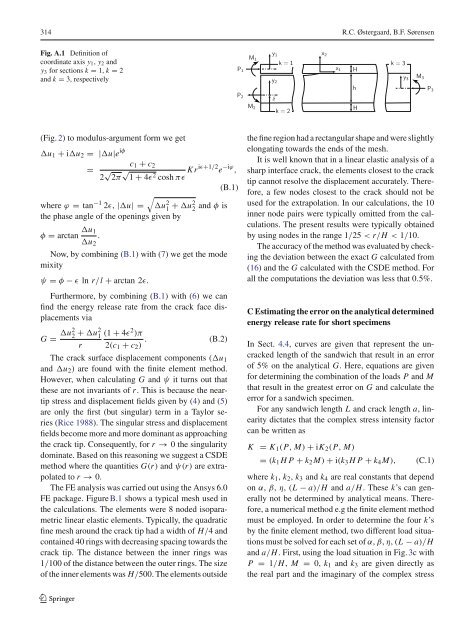
Fig. A.1 Definition of<br />
coordinate axis y1, y2 and<br />
y3 for sections k = 1, k = 2<br />
and k = 3, respectively<br />
(Fig. 2) to modulus-argument form we get<br />
u1 + iu2 = |u|e iφ<br />
c1 + c2<br />
=<br />
2 √ 2π √ 1 + 4ɛ2 cosh πɛ Kriɛ+1/2e −iϕ ,<br />
(B.1)<br />
where ϕ = tan−1 <br />
2ɛ, |u| = u2 1 + u2 2 and φ is<br />
the phase angle of the openings given by<br />
φ = arctan u1<br />
.<br />
u2<br />
Now, by combining (B.1) with (7) we get the mode<br />
mixity<br />
ψ = φ − ɛ ln r/l + arctan 2ɛ.<br />
Furthermore, by combining (B.1) with (6) we can<br />
find the energy release rate from the crack face displacements<br />
via<br />
G = u2 2 + u2 1<br />
r<br />
(1 + 4ɛ2 )π<br />
. (B.2)<br />
2(c1 + c2)<br />
The crack surface displacement components (u1<br />
and u2) are found with the finite element method.<br />
However, when calculating G and ψ it turns out that<br />
these are not invariants of r. This is because the neartip<br />
stress and displacement fields given by (4) and (5)<br />
are only the first (but singular) term in a Taylor series<br />
(Rice 1988). The singular stress and displacement<br />
fields become more and more dominant as approaching<br />
the crack tip. Consequently, for r → 0 the singularity<br />
dominate. Based on this reasoning we suggest a CSDE<br />
method where the quantities G(r) and ψ(r) are extrapolated<br />
to r → 0.<br />
The FE analysis was carried out using the Ansys 6.0<br />
FE package. Figure B.1 shows a typical mesh used in<br />
the calculations. The elements were 8 noded isoparametric<br />
linear elastic elements. Typically, the quadratic<br />
fine mesh around the crack tip had a width of H/4 and<br />
contained 40 rings with decreasing spacing towards the<br />
crack tip. The distance between the inner rings was<br />
1/100 of the distance between the outer rings. The size<br />
of the inner elements was H/500. The elements outside<br />
123<br />
P1<br />
P2<br />
M1<br />
M2<br />
y1<br />
y2<br />
δ<br />
k = 1<br />
k = 2<br />
x2<br />
x1<br />
H<br />
h<br />
H<br />
k = 3<br />
the fine region had a rectangular shape and were slightly<br />
elongating towards the ends of the mesh.<br />
It is well known that in a linear elastic analysis of a<br />
sharp interface crack, the elements closest to the crack<br />
tip cannot resolve the displacement accurately. Therefore,<br />
a few nodes closest to the crack should not be<br />
used for the extrapolation. In our calculations, the 10<br />
inner node pairs were typically omitted from the calculations.<br />
The present results were typically obtained<br />
by using nodes in the range 1/25 < r/H < 1/10.<br />
The accuracy of the method was evaluated by checking<br />
the deviation between the exact G calculated from<br />
(16) and the G calculated with the CSDE method. For<br />
all the computations the deviation was less that 0.5%.<br />
C Estimating the error on the analytical determined<br />
energy release rate for short specimens<br />
In Sect. 4.4, curves are given that represent the uncracked<br />
length of the sandwich that result in an error<br />
of 5% on the analytical G. Here, equations are given<br />
for determining the combination of the loads P and M<br />
that result in the greatest error on G and calculate the<br />
error for a sandwich specimen.<br />
For any sandwich length L and crack length a, linearity<br />
dictates that the complex stress intensity factor<br />
can be written as<br />
K = K1(P, M) + iK2(P, M)<br />
= (k1HP+ k2M) + i(k3HP+ k4M), (C.1)<br />
where k1, k2, k3 and k4 are real constants that depend<br />
on α, β, η, (L − a)/H and a/H. These k’s can generally<br />
not be determined by analytical means. Therefore,<br />
a numerical method e.g the finite element method<br />
must be employed. In order to determine the four k’s<br />
by the finite element method, two different load situations<br />
must be solved for each set of α, β, η, (L − a)/H<br />
and a/H. First, using the load situation in Fig. 3c with<br />
P = 1/H, M = 0, k1 and k3 are given directly as<br />
the real part and the imaginary of the complex stress<br />
y3<br />
M3<br />
P3


