Rasmus ÿstergaard forside 100%.indd - Solid Mechanics
Rasmus ÿstergaard forside 100%.indd - Solid Mechanics Rasmus ÿstergaard forside 100%.indd - Solid Mechanics
Interface crack in sandwich specimen 313 verse forces that are also of major importance in many practical applications. This has the implication that the moment applied to the sandwich must be pure moments and cannot be introduced by a transverse force. In the presence of a transverse shear force, the analysis becomes more comprehensive. Then, the energy release rate is dependent on β, the crack length and numerical calculation of corrections for the energy release rate must be determined Li et al. (2004). Furthermore, another phase angle must be calculated for the transverse force. An extension of the present analysis to include the effect of transverse forces would be of great interest and would complete the analysis of fracture of the sandwich specimen. 7 Summary and conclusions In the present work, some aspects of debonding of sandwich structures have been analyzed within the framework of linear elastic fracture mechanics. The problem of a delaminated sandwich structure loaded with end-loads and moments was recast into an equivalent, reduced problem consisting of only two independent load parameters. The energy release rate was evaluated and presented in closed-analytical form by evaluation of the J-integral. Furthermore, a loadindependent phase angle was introduced so the mode mixity could be determined for any combination of the loads. This phase angle was computed for a number of relevant sandwich configurations using a novel CSDE method. The analytical results were based on classical beam theory. This is an exact solution for long specimens. However, for short specimens, the stresses at the ends of the sandwich specimen are affected by the crack tip stress field. Then, the present analysis is not strictly applicable. An analysis was made to determine minimum specimen length for which the analytical solution for the energy release rate and mode mixity are accurate. For sandwich specimens with moderate elastic mismatch between face sheets and core the results are fairly accurate unless the uncracked part of the sandwich becomes shorter than 10H. For materials with very large elastic mismatch, the uncracked part of the sandwich specimen must be significantly longer. Appendix A The stress along the edges of a sandwich containing an interface crack In order to evaluate the J-integral, the stresses along the beam end-sections must be known. Three end-sections, denoted k = 1, 2 and 3, respectively, are considered: at x1 =−a and x2 > 0(k = 1), x1 =−a and x2 < 0 (k = 2), x1 = L − a (k = 3). The sandwich specimen is loaded by moments Mk and normal forces Pk (k = 1, 2, 3). The strain, ɛ11,k, along the beam end-section, k, where Mk and Pk act, can be found from classic beam theory which is an exact solution when no shear stresses are present ɛ11,k(yk) = yk Pk + E dyk Pk + Mk Mk yk y2 k dyk yk = Ē2hAk Ē2h 3 yk, Ik where yk is the distance from the neutral axis of section number k. That is y1 = x2 − H/2, y2 = x2 + H +h −δ and y3 = x2+h/2, see Fig. A.1. Mk and Pk are positive as defined in Figs. 1 and A.1. The stresses are found according to Hooke’s law σ11(yk) = Ē(yk)ɛ11(yk), where the appropriate Ē must be used (Ē1 for −h ≤ x2 ≤ 0 and Ē2 otherwise). For k = 1 the constants involved in the strain expression are A1 = 1 η and I1 = 1 . 12η3 For k = 2 the strains are calculated using Suo and Hutchinson (1990): A2 = 1 + η I2 = 1 + − 3η3 η 1 1 + η η − 2 1 + − + η 1 . 3 For k = 3 we find A3 = 2 η + and I3 = 2 3 3 + + + η3 2η η2 4 . B Extracting the mode mixity and energy release rate from a finite element model The complex stress intensity factor is related to the crack displacement components via (Fig. 2). Rewriting 123
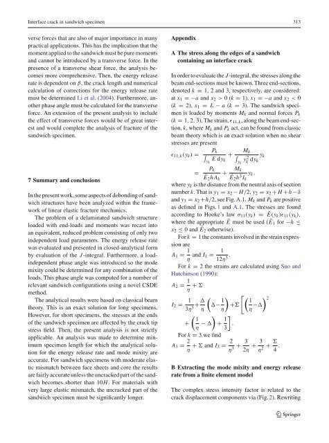
314 R.C. Østergaard, B.F. Sørensen Fig. A.1 Definition of coordinate axis y1, y2 and y3 for sections k = 1, k = 2 and k = 3, respectively (Fig. 2) to modulus-argument form we get u1 + iu2 = |u|e iφ c1 + c2 = 2 √ 2π √ 1 + 4ɛ2 cosh πɛ Kriɛ+1/2e −iϕ , (B.1) where ϕ = tan−1 2ɛ, |u| = u2 1 + u2 2 and φ is the phase angle of the openings given by φ = arctan u1 . u2 Now, by combining (B.1) with (7) we get the mode mixity ψ = φ − ɛ ln r/l + arctan 2ɛ. Furthermore, by combining (B.1) with (6) we can find the energy release rate from the crack face displacements via G = u2 2 + u2 1 r (1 + 4ɛ2 )π . (B.2) 2(c1 + c2) The crack surface displacement components (u1 and u2) are found with the finite element method. However, when calculating G and ψ it turns out that these are not invariants of r. This is because the neartip stress and displacement fields given by (4) and (5) are only the first (but singular) term in a Taylor series (Rice 1988). The singular stress and displacement fields become more and more dominant as approaching the crack tip. Consequently, for r → 0 the singularity dominate. Based on this reasoning we suggest a CSDE method where the quantities G(r) and ψ(r) are extrapolated to r → 0. The FE analysis was carried out using the Ansys 6.0 FE package. Figure B.1 shows a typical mesh used in the calculations. The elements were 8 noded isoparametric linear elastic elements. Typically, the quadratic fine mesh around the crack tip had a width of H/4 and contained 40 rings with decreasing spacing towards the crack tip. The distance between the inner rings was 1/100 of the distance between the outer rings. The size of the inner elements was H/500. The elements outside 123 P1 P2 M1 M2 y1 y2 δ k = 1 k = 2 x2 x1 H h H k = 3 the fine region had a rectangular shape and were slightly elongating towards the ends of the mesh. It is well known that in a linear elastic analysis of a sharp interface crack, the elements closest to the crack tip cannot resolve the displacement accurately. Therefore, a few nodes closest to the crack should not be used for the extrapolation. In our calculations, the 10 inner node pairs were typically omitted from the calculations. The present results were typically obtained by using nodes in the range 1/25 < r/H < 1/10. The accuracy of the method was evaluated by checking the deviation between the exact G calculated from (16) and the G calculated with the CSDE method. For all the computations the deviation was less that 0.5%. C Estimating the error on the analytical determined energy release rate for short specimens In Sect. 4.4, curves are given that represent the uncracked length of the sandwich that result in an error of 5% on the analytical G. Here, equations are given for determining the combination of the loads P and M that result in the greatest error on G and calculate the error for a sandwich specimen. For any sandwich length L and crack length a, linearity dictates that the complex stress intensity factor can be written as K = K1(P, M) + iK2(P, M) = (k1HP+ k2M) + i(k3HP+ k4M), (C.1) where k1, k2, k3 and k4 are real constants that depend on α, β, η, (L − a)/H and a/H. These k’s can generally not be determined by analytical means. Therefore, a numerical method e.g the finite element method must be employed. In order to determine the four k’s by the finite element method, two different load situations must be solved for each set of α, β, η, (L − a)/H and a/H. First, using the load situation in Fig. 3c with P = 1/H, M = 0, k1 and k3 are given directly as the real part and the imaginary of the complex stress y3 M3 P3
- Page 52 and 53: Pcr P gl 1 0.8 0.6 0.4 0.2 0.01 0.0
- Page 54 and 55: 0.6 0.5 0.4 0.3 0.2 0.1 initial cra
- Page 56 and 57: P P gl P P gl 1 0.8 0.6 0.4 0.2 1 5
- Page 58 and 59: ˆσ
- Page 60 and 61: JR σn σt U ∗ n JR
- Page 62 and 63: E
- Page 64 and 65: σn(Un/H)ℓ EfH = Pn EfH σt(Ut
- Page 66 and 67: (Ut ≡ 0)
- Page 68 and 69: Γ/HEf.
- Page 70 and 71: α
- Page 72 and 73: ϕ = −30 ◦ ◦ −60 , ϕ = −
- Page 74 and 75: β0,
- Page 76 and 77: β0,
- Page 78 and 79: ˆσi < ˆσcore ˆσi ˆσcore
- Page 80 and 81: © ©
- Page 82 and 83: ¥
- Page 84 and 85: £
- Page 86 and 87: £
- Page 88 and 89: ¥
- Page 90 and 91: Int J Fract (2007) 143:301-316 DOI
- Page 92 and 93: Interface crack in sandwich specime
- Page 94 and 95: Interface crack in sandwich specime
- Page 96 and 97: Interface crack in sandwich specime
- Page 98 and 99: Interface crack in sandwich specime
- Page 100 and 101: Interface crack in sandwich specime
- Page 104 and 105: Interface crack in sandwich specime
- Page 106 and 107: [P2] Journal of Sandwich Structures
- Page 108 and 109: 446 R. C. ØSTERGAARD ET AL. widesp
- Page 110 and 111: 448 R. C. ØSTERGAARD ET AL. core a
- Page 112 and 113: 450 R. C. ØSTERGAARD ET AL. The mo
- Page 114 and 115: 452 R. C. ØSTERGAARD ET AL. Energy
- Page 116 and 117: 454 R. C. ØSTERGAARD ET AL. (a) (b
- Page 118 and 119: 456 R. C. ØSTERGAARD ET AL. (a) (b
- Page 120 and 121: 458 R. C. ØSTERGAARD ET AL. (a) (b
- Page 122 and 123: 460 R. C. ØSTERGAARD ET AL. (a) (b
- Page 124 and 125: 462 R. C. ØSTERGAARD ET AL. proces
- Page 126 and 127: 464 R. C. ØSTERGAARD ET AL. APPEND
- Page 128 and 129: 466 R. C. ØSTERGAARD ET AL. 7. Zen
- Page 130 and 131: Abstract Buckling driven debonding
- Page 132 and 133: 1266 R.C. Østergaard / Internation
- Page 134 and 135: 1268 R.C. Østergaard / Internation
- Page 136 and 137: 1270 R.C. Østergaard / Internation
- Page 138 and 139: 1272 R.C. Østergaard / Internation
- Page 140 and 141: 1274 R.C. Østergaard / Internation
- Page 142 and 143: 1276 R.C. Østergaard / Internation
- Page 144 and 145: 1278 R.C. Østergaard / Internation
- Page 146 and 147: 1280 R.C. Østergaard / Internation
- Page 148: 1282 R.C. Østergaard / Internation
Interface crack in sandwich specimen 313<br />
verse forces that are also of major importance in many<br />
practical applications. This has the implication that the<br />
moment applied to the sandwich must be pure moments<br />
and cannot be introduced by a transverse force. In the<br />
presence of a transverse shear force, the analysis becomes<br />
more comprehensive. Then, the energy release<br />
rate is dependent on β, the crack length and numerical<br />
calculation of corrections for the energy release rate<br />
must be determined Li et al. (2004). Furthermore, another<br />
phase angle must be calculated for the transverse<br />
force. An extension of the present analysis to include<br />
the effect of transverse forces would be of great interest<br />
and would complete the analysis of fracture of the<br />
sandwich specimen.<br />
7 Summary and conclusions<br />
In the present work, some aspects of debonding of sandwich<br />
structures have been analyzed within the framework<br />
of linear elastic fracture mechanics.<br />
The problem of a delaminated sandwich structure<br />
loaded with end-loads and moments was recast into<br />
an equivalent, reduced problem consisting of only two<br />
independent load parameters. The energy release rate<br />
was evaluated and presented in closed-analytical form<br />
by evaluation of the J-integral. Furthermore, a loadindependent<br />
phase angle was introduced so the mode<br />
mixity could be determined for any combination of the<br />
loads. This phase angle was computed for a number of<br />
relevant sandwich configurations using a novel CSDE<br />
method.<br />
The analytical results were based on classical beam<br />
theory. This is an exact solution for long specimens.<br />
However, for short specimens, the stresses at the ends<br />
of the sandwich specimen are affected by the crack tip<br />
stress field. Then, the present analysis is not strictly<br />
applicable. An analysis was made to determine minimum<br />
specimen length for which the analytical solution<br />
for the energy release rate and mode mixity are<br />
accurate. For sandwich specimens with moderate elastic<br />
mismatch between face sheets and core the results<br />
are fairly accurate unless the uncracked part of the sandwich<br />
becomes shorter than 10H. For materials with<br />
very large elastic mismatch, the uncracked part of the<br />
sandwich specimen must be significantly longer.<br />
Appendix<br />
A The stress along the edges of a sandwich<br />
containing an interface crack<br />
In order to evaluate the J-integral, the stresses along the<br />
beam end-sections must be known. Three end-sections,<br />
denoted k = 1, 2 and 3, respectively, are considered:<br />
at x1 =−a and x2 > 0(k = 1), x1 =−a and x2 < 0<br />
(k = 2), x1 = L − a (k = 3). The sandwich specimen<br />
is loaded by moments Mk and normal forces Pk<br />
(k = 1, 2, 3). The strain, ɛ11,k, along the beam end-section,<br />
k, where Mk and Pk act, can be found from classic<br />
beam theory which is an exact solution when no shear<br />
stresses are present<br />
ɛ11,k(yk) =<br />
<br />
yk<br />
Pk<br />
+ <br />
E dyk<br />
Pk<br />
+ Mk<br />
Mk<br />
yk y2 k dyk<br />
yk<br />
=<br />
Ē2hAk Ē2h 3 yk,<br />
Ik<br />
where yk is the distance from the neutral axis of section<br />
number k. That is y1 = x2 − H/2, y2 = x2 + H +h −δ<br />
and y3 = x2+h/2, see Fig. A.1. Mk and Pk are positive<br />
as defined in Figs. 1 and A.1. The stresses are found<br />
according to Hooke’s law σ11(yk) = Ē(yk)ɛ11(yk),<br />
where the appropriate Ē must be used (Ē1 for −h ≤<br />
x2 ≤ 0 and Ē2 otherwise).<br />
For k = 1 the constants involved in the strain expression<br />
are<br />
A1 = 1<br />
η and I1 = 1<br />
.<br />
12η3 For k = 2 the strains are calculated using Suo and<br />
Hutchinson (1990):<br />
A2 = 1<br />
+ <br />
η<br />
I2 = 1<br />
<br />
+ −<br />
3η3 η<br />
1<br />
1<br />
+<br />
η η −<br />
2 <br />
1<br />
+ − +<br />
η 1<br />
<br />
.<br />
3<br />
For k = 3 we find<br />
A3 = 2<br />
η + and I3 = 2 3 3 <br />
+ + +<br />
η3 2η η2 4 .<br />
B Extracting the mode mixity and energy release<br />
rate from a finite element model<br />
The complex stress intensity factor is related to the<br />
crack displacement components via (Fig. 2). Rewriting<br />
123


