Experimental and Numerical Study of Swirling ... - Solid Mechanics
Experimental and Numerical Study of Swirling ... - Solid Mechanics Experimental and Numerical Study of Swirling ... - Solid Mechanics
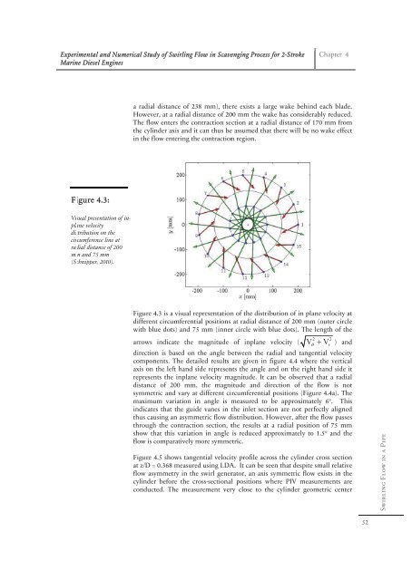
Experi imental and Numerical N Stud dy of Swirling g Flow in Scaveenging Processs for 2-Stroke Marin ne Diesel Engin nes Fi igure 4.3: Vis sual presentation n of in- pla ane velocity dis stribution on the cir rcumference line at a rad dial distance of 200 2 mm m and 75 mm (Sc chnipper, 2010). Chapter 4 a radial l distance of 238 2 mm), theere exists a larrge wake behiind each bladde. Howeve er, at a radial distance of 2000 mm the waake has considderably reduceed. The flow w enters the contraction c seection at a raddial distance of 170 mm from the cylinder axis and it can thus bee assumed that there will bee no wake effeect in the flow fl entering the t contractionn region. Figure 4.3 4 is a visual representationn of the distribbution of in pplane velocity at differen nt circumferen ntial positions at radial distaance of 200 mmm (outer circcle with blue dots) and 75 mm (innerr circle with bblue dots). Thhe length of thhe 2 2 arrows indicate the e magnitude of inplane velocity ( V V Vr ) annd directio on is based on n the angle bbetween the raadial and tanngential velociity compon nents. The detailed results are given in figure 4.4 whhere the verticcal axis on the left hand d side represennts the angle aand on the rigght hand side it represen nts the inplan ne velocity maagnitude. It ccan be observeed that a radiial distance e of 200 mm m, the magnitude and diirection of thhe flow is not symmet tric and vary at different ciircumferentiall positions (Fiigure 4.4a). Thhe maximu um variation in angle is measured to be approximmately 6°. Thhis indicate es that the gu uide vanes in the inlet sectiion are not perfectly aligneed thus cau using an asym mmetric flow ddistribution. HHowever, afterr the flow passses through h the contract tion section, tthe results at a radial position of 75 mm show th hat this variat tion in angle is reduced appproximately to 1.5° and thhe flow is comparatively c y more symmeetric. Figure 4.5 4 shows tan ngential velociity profile acrooss the cylindder cross sectioon at z/D = 0.368 measur red using LDAA. It can be seeen that despitte small relativve flow asy ymmetry in th he swirl generrator, an axis symmetric floow exists in thhe cylinder before the cross-sectionaal positions wwhere PIV meeasurements aare conducted. The mea asurement verry close to thhe cylinder geeometric centter 52 Swirling Flow in a Pipe
Experi imental and Numerical N Stud dy of Swirling g Flow in Scaveenging Processs for 2-Stroke Marin ne Diesel Engin nes Fig gure 4.4: Circ cumferential distr ribution of inplan ne veloc city magnitude and a angl le between radial l and tang gential velocity comp ponents (a) radiu us = 200 mm (b) radius = 75 mm (Schnipper, 2010 0). Figu ure 4.5: Cross s-Sectional Tang gential Velocity Profle e. (X/R=0) ) was not con nducted due tto bad signal and thus figuure 4.5 may not give exa act size of the vortex v core at the given crosss-sectional plane. (a) (b) Chapter 4 53 Swirling Flow in a Pipe
- Page 21 and 22: Experimental and Numerical Study of
- Page 23 and 24: Experi imental and Numerical N Stud
- Page 25 and 26: Experi imental and Numerical N Stud
- Page 27 and 28: Experimental and Numerical Study of
- Page 29 and 30: Experimental and Numerical Study of
- Page 31 and 32: Experimental and Numerical Study of
- Page 33 and 34: Experimental and Numerical Study of
- Page 35 and 36: Experi imental and Numerical N Stud
- Page 37 and 38: Experi imental and Numerical N Stud
- Page 39 and 40: Experi imental and Numerical N Stud
- Page 41 and 42: Experi imental and Numerical N Stud
- Page 43 and 44: Experimental and Numerical Study of
- Page 45 and 46: Experi imental and Numerical N Stud
- Page 47 and 48: Experi imental and Numerical N Stud
- Page 49 and 50: Experimental and Numerical Study of
- Page 51 and 52: Experi imental and Numerical N Stud
- Page 53 and 54: Experi imental and Numerical N Stud
- Page 55 and 56: Experimental and Numerical Study of
- Page 57 and 58: Experimental and Numerical Study of
- Page 59 and 60: Experi imental and Numerical N Stud
- Page 61 and 62: Experi imental and Numerical N Stud
- Page 63 and 64: Experi imental and Numerical N Stud
- Page 65 and 66: Experi imental and Numerical N Stud
- Page 67 and 68: Experi imental and Numerical N Stud
- Page 69 and 70: Experimental and Numerical Study of
- Page 71: Experimental and Numerical Study of
- Page 75 and 76: Experi imental and Numerical N Stud
- Page 77 and 78: Experi imental and Numerical N Stud
- Page 79 and 80: Experi imental and Numerical N Stud
- Page 81 and 82: Experi imental and Numerical N Stud
- Page 83 and 84: Experimental and Numerical Study of
- Page 85 and 86: Experimental and Numerical Study of
- Page 87 and 88: Experi imental and Numerical N Stud
- Page 89 and 90: Experi imental and Numerical N Stud
- Page 91 and 92: Experi imental and Numerical N Stud
- Page 93 and 94: Experi imental and Numerical N Stud
- Page 95 and 96: Experi imental and Numerical N Stud
- Page 97 and 98: Experi imental and Numerical N Stud
- Page 99 and 100: Experi imental and Numerical N Stud
- Page 101 and 102: Experi imental and Numerical N Stud
- Page 103 and 104: Experi imental and Numerical N Stud
- Page 105 and 106: Experi imental and Numerical N Stud
- Page 107 and 108: Experi imental and Numerical N Stud
- Page 109 and 110: Experi imental and Numerical N Stud
- Page 111 and 112: Experi imental and Numerical N Stud
- Page 113 and 114: Experi imental and Numerical N Stud
- Page 115 and 116: Experi imental and Numerical N Stud
- Page 117 and 118: Experi imental and Numerical N Stud
- Page 119 and 120: Experi imental and Numerical N Stud
- Page 121 and 122: Experi imental and Numerical N Stud
Experi imental <strong>and</strong> <strong>Numerical</strong> N Stud dy <strong>of</strong> <strong>Swirling</strong> g Flow in Scaveenging<br />
Processs<br />
for 2-Stroke<br />
Marin ne Diesel Engin nes<br />
Fi igure 4.3:<br />
Vis sual presentation n <strong>of</strong> in-<br />
pla ane velocity<br />
dis stribution on the<br />
cir rcumference line at a<br />
rad dial distance <strong>of</strong> 200 2<br />
mm m <strong>and</strong> 75 mm<br />
(Sc chnipper, 2010).<br />
Chapter 4<br />
a radial l distance <strong>of</strong> 238 2 mm), theere<br />
exists a larrge<br />
wake behiind<br />
each bladde.<br />
Howeve er, at a radial distance <strong>of</strong> 2000<br />
mm the waake<br />
has considderably<br />
reduceed.<br />
The flow w enters the contraction c seection<br />
at a raddial<br />
distance <strong>of</strong><br />
170 mm from<br />
the cylinder<br />
axis <strong>and</strong> it can thus bee<br />
assumed that<br />
there will bee<br />
no wake effeect<br />
in the flow fl entering the t contractionn<br />
region.<br />
Figure 4.3 4 is a visual representationn<br />
<strong>of</strong> the distribbution<br />
<strong>of</strong> in pplane<br />
velocity at<br />
differen nt circumferen ntial positions at radial distaance<br />
<strong>of</strong> 200 mmm<br />
(outer circcle<br />
with blue<br />
dots) <strong>and</strong> 75 mm (innerr<br />
circle with bblue<br />
dots). Thhe<br />
length <strong>of</strong> thhe<br />
2 2<br />
arrows indicate the e magnitude <strong>of</strong> inplane velocity ( V V Vr ) annd<br />
directio on is based on n the angle bbetween<br />
the raadial<br />
<strong>and</strong> tanngential<br />
velociity<br />
compon nents. The detailed<br />
results are given in figure 4.4 whhere<br />
the verticcal<br />
axis on the left h<strong>and</strong> d side represennts<br />
the angle a<strong>and</strong><br />
on the rigght<br />
h<strong>and</strong> side it<br />
represen nts the inplan ne velocity maagnitude.<br />
It ccan<br />
be observeed<br />
that a radiial<br />
distance e <strong>of</strong> 200 mm m, the magnitude<br />
<strong>and</strong> diirection<br />
<strong>of</strong> thhe<br />
flow is not<br />
symmet tric <strong>and</strong> vary at different ciircumferentiall<br />
positions (Fiigure<br />
4.4a). Thhe<br />
maximu um variation in angle is measured to be approximmately<br />
6°. Thhis<br />
indicate es that the gu uide vanes in the inlet sectiion<br />
are not perfectly<br />
aligneed<br />
thus cau using an asym mmetric flow ddistribution.<br />
HHowever,<br />
afterr<br />
the flow passses<br />
through h the contract tion section, tthe<br />
results at a radial position<br />
<strong>of</strong> 75 mm<br />
show th hat this variat tion in angle is reduced appproximately<br />
to 1.5° <strong>and</strong> thhe<br />
flow is comparatively<br />
c<br />
y more symmeetric.<br />
Figure 4.5 4 shows tan ngential velociity<br />
pr<strong>of</strong>ile acrooss<br />
the cylindder<br />
cross sectioon<br />
at z/D = 0.368 measur red using LDAA.<br />
It can be seeen<br />
that despitte<br />
small relativve<br />
flow asy ymmetry in th he swirl generrator,<br />
an axis symmetric floow<br />
exists in thhe<br />
cylinder<br />
before the cross-sectionaal<br />
positions wwhere<br />
PIV meeasurements<br />
aare<br />
conducted.<br />
The mea asurement verry<br />
close to thhe<br />
cylinder geeometric<br />
centter<br />
52<br />
<strong>Swirling</strong> Flow in a Pipe


