Experimental and Numerical Study of Swirling ... - Solid Mechanics
Experimental and Numerical Study of Swirling ... - Solid Mechanics Experimental and Numerical Study of Swirling ... - Solid Mechanics
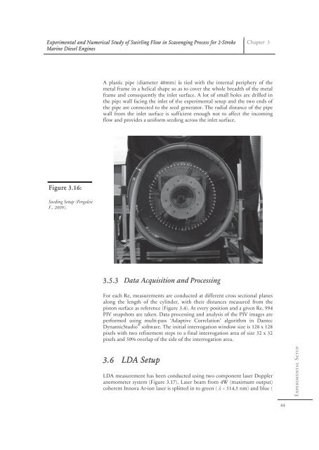
Experi imental and Numerical N Stud dy of Swirling g Flow in Scaveenging Processs for 2-Stroke Marin ne Diesel Engin nes Figu ure 3.16: Seedin ng Setup (Pergole esi F., 200 09). A plastic pipe (diam meter 40mm) iis tied with tthe internal pperiphery of thhe metal frame fr in a heli ical shape so aas to cover thee whole breaddth of the mettal frame and a consequen ntly the inlet surface. A lott of small holees are drilled in the pipe wall facing the inlet of thhe experimenttal setup and tthe two ends of the pipe e are connecte ed to the seedd generator. Thhe radial distaance of the pippe wall fro om the inlet surface s is suffficient enoughh not to affecct the incominng flow an nd provides a uniform u seedinng across the iinlet surface. 3.5.3 For each Re, measure along the t length of piston surface s as refer PIV sna apshots are tak perform med using m Dynam micStudio pixels w pixels a ® ements are coonducted at diifferent cross ssectional plannes the cylinder, , with their ddistances meassured from thhe rence (Figure 3.4). At everyy position and a given Re, 9994 ken. Data proocessing and annalysis of the PIV images aare ulti-pass ‘Adaaptive Correlation’ algoritthm in Dantec soft tware. The initial interrogattion window ssize is 128 x 1228 with two refin nement steps tto a final interrrogation areaa of size 32 x 332 nd 50% overla ap of the side oof the interroggation area. 3.6 Data Acq quisition aand Process ssing LDA Set tup Chapter 3 LDA measurement m has h been conduucted using twwo componennt laser Doppller anemom meter system (Figure 3.17). Laser beam ffrom 4W (maaximum outpuut) coheren nt Innova Ar-ion laser is spliitted in to greeen ( = 514.5 nm) and bluee ( 44 Experimental Setup
Experi imental and Numerical N Stud dy of Swirling g Flow in Scaveenging Processs for 2-Stroke Marin ne Diesel Engin nes Figu ure 3.17: LDA Setup. S Chapter 3 = 488 8 nm) lines usi ing a beam splitter and thenn transmitted through opticcal fiber. The T data is an nalyzed usingg Dantec Bursst Spectrum AAnalyzer (BSAA) Flow v 2.12. The flow w was seeded uusing the seediing setup desccribed in sectioon 3.5.2. For F measurem ments the laser power used iss 3.5-4W and ddata acquisitioon are con nducted by ru unning the syystem in burstt mode. The traverse system controlled using the BSA Flow sooftware, is ussed for positiooning the laseer. The geo ometric center r of the test cyylinder is used as origin for X and Y axes. IIn axial direction (along g Z-axis) the mmeasurementss are conducteed at a distance of 20 mm m from the surface of the piston. Thus tthe measuremments conducteed along X and Y axes give g the velocitty values in thhe middle of tthe two walls of the swir rl generator i.e e. 50 mm fromm each wall (FFigure 3.18). Two se ets of measure ements are coonducted. In first one connducted by thhe author, the measurem ments are condducted along a line followiing the X-axis at a distan nce of 20 mm from the pistoon surface andd at a distancee of z/D = 0.3668. In the second set co onducted by Schnipper (22010), the meeasurements aare conducted along the e circumferencce at a radial distance of 2200 mm and 775 mm fro om the origin (label ‘b’ indiicating red dotts in Figure 3. .18). In order to measure e the flow pro ofile behind thhe guide vaness and decay off correspondinng wake effect e at diff ferent radial positions, addditional meaasurements aare conducted along an arc a and at radiial positions oof 230 mm andd 200 mm (labbel ‘a’ indic cating blue arc cs in Figure 3. 18). 45 Experimental Setup
- Page 13 and 14: Experimental and Numerical Study of
- Page 15 and 16: Experimental and Numerical Study of
- Page 17 and 18: Experimental and Numerical Study of
- Page 19 and 20: Experimental and Numerical Study of
- Page 21 and 22: Experimental and Numerical Study of
- Page 23 and 24: Experi imental and Numerical N Stud
- Page 25 and 26: Experi imental and Numerical N Stud
- Page 27 and 28: Experimental and Numerical Study of
- Page 29 and 30: Experimental and Numerical Study of
- Page 31 and 32: Experimental and Numerical Study of
- Page 33 and 34: Experimental and Numerical Study of
- Page 35 and 36: Experi imental and Numerical N Stud
- Page 37 and 38: Experi imental and Numerical N Stud
- Page 39 and 40: Experi imental and Numerical N Stud
- Page 41 and 42: Experi imental and Numerical N Stud
- Page 43 and 44: Experimental and Numerical Study of
- Page 45 and 46: Experi imental and Numerical N Stud
- Page 47 and 48: Experi imental and Numerical N Stud
- Page 49 and 50: Experimental and Numerical Study of
- Page 51 and 52: Experi imental and Numerical N Stud
- Page 53 and 54: Experi imental and Numerical N Stud
- Page 55 and 56: Experimental and Numerical Study of
- Page 57 and 58: Experimental and Numerical Study of
- Page 59 and 60: Experi imental and Numerical N Stud
- Page 61 and 62: Experi imental and Numerical N Stud
- Page 63: Experi imental and Numerical N Stud
- Page 67 and 68: Experi imental and Numerical N Stud
- Page 69 and 70: Experimental and Numerical Study of
- Page 71 and 72: Experimental and Numerical Study of
- Page 73 and 74: Experi imental and Numerical N Stud
- Page 75 and 76: Experi imental and Numerical N Stud
- Page 77 and 78: Experi imental and Numerical N Stud
- Page 79 and 80: Experi imental and Numerical N Stud
- Page 81 and 82: Experi imental and Numerical N Stud
- Page 83 and 84: Experimental and Numerical Study of
- Page 85 and 86: Experimental and Numerical Study of
- Page 87 and 88: Experi imental and Numerical N Stud
- Page 89 and 90: Experi imental and Numerical N Stud
- Page 91 and 92: Experi imental and Numerical N Stud
- Page 93 and 94: Experi imental and Numerical N Stud
- Page 95 and 96: Experi imental and Numerical N Stud
- Page 97 and 98: Experi imental and Numerical N Stud
- Page 99 and 100: Experi imental and Numerical N Stud
- Page 101 and 102: Experi imental and Numerical N Stud
- Page 103 and 104: Experi imental and Numerical N Stud
- Page 105 and 106: Experi imental and Numerical N Stud
- Page 107 and 108: Experi imental and Numerical N Stud
- Page 109 and 110: Experi imental and Numerical N Stud
- Page 111 and 112: Experi imental and Numerical N Stud
- Page 113 and 114: Experi imental and Numerical N Stud
Experi imental <strong>and</strong> <strong>Numerical</strong> N Stud dy <strong>of</strong> <strong>Swirling</strong> g Flow in Scaveenging<br />
Processs<br />
for 2-Stroke<br />
Marin ne Diesel Engin nes<br />
Figu ure 3.16:<br />
Seedin ng Setup (Pergole esi<br />
F., 200 09).<br />
A plastic<br />
pipe (diam meter 40mm) iis<br />
tied with tthe<br />
internal pperiphery<br />
<strong>of</strong> thhe<br />
metal frame fr in a heli ical shape so aas<br />
to cover thee<br />
whole breaddth<br />
<strong>of</strong> the mettal<br />
frame <strong>and</strong> a consequen ntly the inlet surface. A lott<br />
<strong>of</strong> small holees<br />
are drilled in<br />
the pipe<br />
wall facing the inlet <strong>of</strong> thhe<br />
experimenttal<br />
setup <strong>and</strong> tthe<br />
two ends <strong>of</strong><br />
the pipe e are connecte ed to the seedd<br />
generator. Thhe<br />
radial distaance<br />
<strong>of</strong> the pippe<br />
wall fro om the inlet surface s is suffficient<br />
enoughh<br />
not to affecct<br />
the incominng<br />
flow an nd provides a uniform u seedinng<br />
across the iinlet<br />
surface.<br />
3.5.3<br />
For each<br />
Re, measure<br />
along the t length <strong>of</strong><br />
piston surface s as refer<br />
PIV sna apshots are tak<br />
perform med using m<br />
Dynam micStudio<br />
pixels w<br />
pixels a<br />
® ements are coonducted<br />
at diifferent<br />
cross ssectional<br />
plannes<br />
the cylinder, , with their ddistances<br />
meassured<br />
from thhe<br />
rence (Figure 3.4). At everyy<br />
position <strong>and</strong> a given Re, 9994<br />
ken. Data proocessing<br />
<strong>and</strong> annalysis<br />
<strong>of</strong> the PIV images aare<br />
ulti-pass ‘Adaaptive<br />
Correlation’<br />
algoritthm<br />
in Dantec<br />
s<strong>of</strong>t tware. The initial<br />
interrogattion<br />
window ssize<br />
is 128 x 1228<br />
with two refin nement steps tto<br />
a final interrrogation<br />
areaa<br />
<strong>of</strong> size 32 x 332<br />
nd 50% overla ap <strong>of</strong> the side o<strong>of</strong><br />
the interroggation<br />
area.<br />
3.6<br />
Data Acq quisition a<strong>and</strong><br />
Process ssing<br />
LDA Set tup<br />
Chapter 3<br />
LDA measurement m<br />
has h been conduucted<br />
using twwo<br />
componennt<br />
laser Doppller<br />
anemom meter system (Figure 3.17). Laser beam ffrom<br />
4W (maaximum<br />
outpuut)<br />
coheren nt Innova Ar-ion<br />
laser is spliitted<br />
in to greeen<br />
( = 514.5 nm) <strong>and</strong> bluee<br />
(<br />
44<br />
<strong>Experimental</strong> Setup


