

Maria Bayard Dühring - Solid Mechanics
Maria Bayard Dühring - Solid Mechanics
Maria Bayard Dühring - Solid Mechanics

Create successful ePaper yourself
Turn your PDF publications into a flip-book with our unique Google optimized e-Paper software.
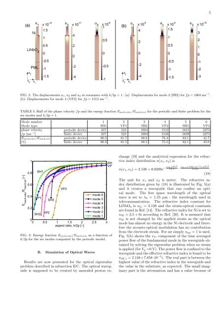
FIG. 2: The displacements u1, u2 and u3 at resonance with h/2p = 1. (a): Displacements for mode 3 (SH2) for fp = 1004 ms −1 .<br />
(b): Displacements for mode 4 (VP2) for fp = 1512 ms −1 .<br />
TABLE I: Half of the phase velocity fp and the energy fraction Emech,elec/Emech,tot for the periodic and finite problem for the<br />
six modes and h/2p = 1.<br />
Mode number 1 2 3 4 5 6<br />
Mode type SH1 VP1 SH2 VP2 SH3 VP3<br />
phase velocity periodic device 337 523 1004 1512 1641 2273<br />
fp [ms −1 ] finite device 337 523 1004 1510 1639 2275<br />
Emech,elec/Emech,tot periodic device 90.5 81.7 88.8 76.4 83.1 41.7<br />
[%] finite device 90.3 81.5 88.5 75.5 82.1 45.0<br />
E mech,elec /E mech,tot [−]<br />
1<br />
0.8<br />
0.6<br />
SH1<br />
VP3<br />
0.4<br />
VP1<br />
mode 6<br />
mode 5<br />
mode 4<br />
0.2<br />
mode 3<br />
SH2<br />
mode 2<br />
mode 1<br />
0<br />
0 0.5 1 1.5 2 2.5 3<br />
aspect ratio, h/2p [−]<br />
VP2<br />
SH3<br />
SH<br />
VP<br />
FIG. 3: Energy fraction Emech,elec/Emech,tot as a function of<br />
h/2p for the six modes computed by the periodic model.<br />
B. Simulation of Optical Waves<br />
Results are now presented for the optical eigenvalue<br />
problem described in subsection II C. The optical waveguide<br />
is supposed to be created by annealed proton ex-<br />
change [19] and the analytical expression for the refractive<br />
index distribution n(x1, x2) is<br />
n(x1, x2) = 2.138 + 0.0289e − (x2 ·106 ) 2<br />
12.5 − (x1−1.7500·10−4 )·10 6 ) 2<br />
15.68 .<br />
(18)<br />
The unit for x1 and x2 is meter. The refractive index<br />
distribution given by (18) is illustrated by Fig. 5(a)<br />
and it creates a waveguide that can confine an optical<br />
mode. The free space wavelength of the optical<br />
wave is set to λ0 = 1.55 µm - the wavelength used in<br />
telecommunication. The refractive index constant for<br />
LiNbO3 is nLi = 2.138 and the strain-optical constants<br />
are found in Ref. [14]. The refractive index for Ni is set to<br />
nNi = 3.5 + 6i according to Ref. [20]. It is assumed that<br />
nNi is not changed by the applied strain as the optical<br />
mode has almost no energy in the Ni electrode and therefore<br />
the acousto-optical modulation has no contribution<br />
from the electrode strain. For air simply nair = 1 is used.<br />
Fig. 5(b) shows the x3- component of the time averaged<br />
power flow of the fundamental mode in the waveguide obtained<br />
by solving the eigenvalue problem when no strain<br />
is applied (for Vp =0 V). The power flow is confined to the<br />
waveguide and the effective refractive index is found to be<br />
neff,1 = 2.148+7.858·10 −5 i. The real part is between the<br />
highest value of the refractive index in the waveguide and<br />
the value in the substrate, as expected. The small imaginary<br />
part is the attenuation and has a value because of<br />
5


