Maria Bayard Dühring - Solid Mechanics
Maria Bayard Dühring - Solid Mechanics
Maria Bayard Dühring - Solid Mechanics
You also want an ePaper? Increase the reach of your titles
YUMPU automatically turns print PDFs into web optimized ePapers that Google loves.
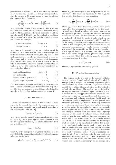
piezoelectric directions. This is indicated by the tilde<br />
above the material tensors. The two governing equations<br />
give the stresses by Newton’s second law and the electric<br />
displacement from Gauss law<br />
1<br />
γj<br />
∂Tij<br />
∂xj<br />
= −ρω 2 ui and<br />
1<br />
γj<br />
∂Dj<br />
∂xj<br />
= 0, (6)<br />
where ρ is the density of the material. The governing<br />
equations are second order differential equations for uj<br />
and V . Mechanical and electrical boundary conditions<br />
must be specified. Considering the mechanical conditions<br />
the upper surface is stress free and the vertical sides and<br />
the bottom are clamped<br />
stress free surface : Tjkmk = 0, (7)<br />
clamped surface : ui = 0, (8)<br />
where mk is the normal unit vector pointing out of the<br />
surface. At the upper surface there are no charges and<br />
therefore electric insulation occurs, meaning that the normal<br />
component of the electric displacement is zero. At<br />
the bottom and to the sides of the domain it is assumed<br />
that the electrical potential is zero whereas at the interface<br />
between the electrodes and the substrate the potential<br />
is ±Vp. The electrical boundary conditions are<br />
summarized as follows<br />
electrical insulation : Dimi = 0, (9)<br />
zero potential : V = 0, (10)<br />
applied positive potential : V = Vp, (11)<br />
applied negative potential : V = −Vp. (12)<br />
The piezoelectric problem is solved by a plane formulation<br />
obtained by omitting all derivatives with respect to<br />
x3. The two governing equations (6) are solved simultaneously<br />
to find the four unknowns u1, u2, u3 and V .<br />
C. The Optical Model<br />
After the mechanical strain in the material is computed<br />
by the piezoelectric model the refractive index nij<br />
in the strained material can be calculated according to<br />
the strain-optical relation [16]<br />
∆bikbkj = ˜pijlmSlm, (13)<br />
where ˜pijlm are the rotated strain-optical constants and<br />
biknkj = δij. For a given optical mode of order ν with<br />
the propagation constant βν the effective refractive index<br />
neff,ν is defined as<br />
neff,ν = βν/k0, (14)<br />
where k0 is the free space propagation constant. It is assumed<br />
that the propagating optical modes have harmonic<br />
solutions on the form<br />
Hp,ν(x1, x2, x3) = Hp,ν(x1, x2)e −iβνx3 , (15)<br />
where Hp,ν are the magnetic field components of the optical<br />
wave. The governing equations for the magnetic<br />
field are the time-harmonic wave equations<br />
<br />
<br />
∂<br />
∂Hp<br />
eijk bklblmemnp − k<br />
∂xj<br />
∂xn<br />
2 0Hi = 0, (16)<br />
where eijk here is the alternating symbol. For a given<br />
value of k0 the propagation constant βν for the possible<br />
modes are found by solving the wave equations as<br />
an eigenvalue problem, whereby the effective refractive<br />
indices are obtained. In this work the set of equations<br />
are reduced such that the model is only solved for the<br />
transverse components of the magnetic field H1 and H2.<br />
As the energy of the lower order optical modes is concentrated<br />
in the waveguide, the optical domain (where the<br />
eigenvalue problem is solved) can be reduced to a smaller<br />
area around the waveguide, see Fig. 1. At the boundary<br />
of this optical domain it is assumed that the magnetic<br />
field is zero as the energy density quickly decays outside<br />
the waveguide. Thus, the perfectly magnetic conductor<br />
boundary condition is applied<br />
eijkHjmk = 0, (17)<br />
where eijk again is the alternating symbol.<br />
D. Practical implementation<br />
The coupled model is solved by the commercial finite<br />
element program Comsol Multiphysics with Matlab [17].<br />
This program is designed for modeling engineering problems<br />
described by partial differential equations and it is<br />
possible to combine different physical models and solve<br />
multiphysics problems. The models can be defined by<br />
writing conventional differential equations directly or it<br />
is possible to use the application modes, which are templates<br />
for specific physical problems with the appropriate<br />
equations and variables predefined. In this work the<br />
piezoelectric model is implemented in the general form<br />
where the governing equations and boundary conditions<br />
are written on divergence form. The optical problems<br />
are solved using the perpendicular waves, hybrid-mode<br />
waves, application mode. The problems are discretized<br />
by a triangular element mesh and second order Lagrange<br />
elements are employed. A sufficient number of elements<br />
must be used in wave problems in order to resolve the<br />
waves and obtain convergence, which typically means<br />
that at least 5-6 second order elements per wavelength<br />
must be employed. In the studied problem the geometry<br />
is complicated and a coupled model is used, so a fine<br />
mesh is employed where the wavelength of the vibration<br />
in the electrodes for the highest frequency is discretized<br />
by at least 10 elements. For a = 7 µm, a maximum element<br />
size of 1.5 µm is used except in the waveguide area<br />
where 0.25 µm is used, see Fig. 1. For the piezoelectric<br />
model it has been tested that the results for the phase<br />
velocity and the mechanical energy did not change for a<br />
3


