Maria Bayard Dühring - Solid Mechanics
Maria Bayard Dühring - Solid Mechanics
Maria Bayard Dühring - Solid Mechanics
You also want an ePaper? Increase the reach of your titles
YUMPU automatically turns print PDFs into web optimized ePapers that Google loves.
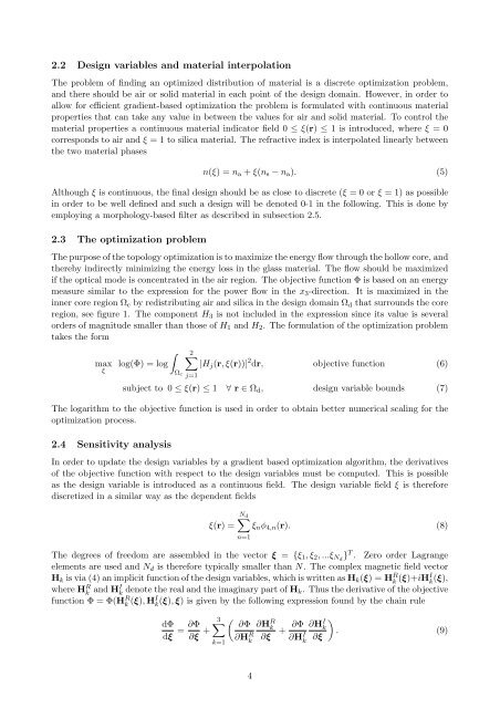
2.2 Design variables and material interpolation<br />
The problem of finding an optimized distribution of material is a discrete optimization problem,<br />
and there should be air or solid material in each point of the design domain. However, in order to<br />
allow for efficient gradient-based optimization the problem is formulated with continuous material<br />
properties that can take any value in between the values for air and solid material. To control the<br />
material properties a continuous material indicator field 0 ≤ ξ(r) ≤ 1 is introduced, where ξ = 0<br />
corresponds to air and ξ = 1 to silica material. The refractive index is interpolated linearly between<br />
the two material phases<br />
n(ξ) = na + ξ(ns − na). (5)<br />
Although ξ is continuous, the final design should be as close to discrete (ξ = 0 or ξ = 1) as possible<br />
in order to be well defined and such a design will be denoted 0-1 in the following. This is done by<br />
employing a morphology-based filter as described in subsection 2.5.<br />
2.3 The optimization problem<br />
The purpose of the topology optimization is to maximize the energy flow through the hollow core, and<br />
thereby indirectly minimizing the energy loss in the glass material. The flow should be maximized<br />
if the optical mode is concentrated in the air region. The objective function Φ is based on an energy<br />
measure similar to the expression for the power flow in the x3-direction. It is maximized in the<br />
inner core region Ωc by redistributing air and silica in the design domain Ωd that surrounds the core<br />
region, see figure 1. The component H3 is not included in the expression since its value is several<br />
orders of magnitude smaller than those of H1 and H2. The formulation of the optimization problem<br />
takes the form<br />
max<br />
ξ<br />
<br />
log(Φ) = log<br />
Ωc j=1<br />
2<br />
|Hj(r, ξ(r))| 2 dr, objective function (6)<br />
subject to 0 ≤ ξ(r) ≤ 1 ∀ r ∈ Ωd, design variable bounds (7)<br />
The logarithm to the objective function is used in order to obtain better numerical scaling for the<br />
optimization process.<br />
2.4 Sensitivity analysis<br />
In order to update the design variables by a gradient based optimization algorithm, the derivatives<br />
of the objective function with respect to the design variables must be computed. This is possible<br />
as the design variable is introduced as a continuous field. The design variable field ξ is therefore<br />
discretized in a similar way as the dependent fields<br />
Nd <br />
ξ(r) = ξnφ4,n(r). (8)<br />
n=1<br />
The degrees of freedom are assembled in the vector ξ = {ξ1, ξ2, ...ξNd }T . Zero order Lagrange<br />
elements are used and Nd is therefore typically smaller than N. The complex magnetic field vector<br />
Hk is via (4) an implicit function of the design variables, which is written as Hk(ξ) = HR k (ξ)+iHI k (ξ),<br />
where HR k and HI k denote the real and the imaginary part of Hk. Thus the derivative of the objective<br />
function Φ = Φ(HR k (ξ), HI k (ξ), ξ) is given by the following expression found by the chain rule<br />
dΦ<br />
dξ<br />
= ∂Φ<br />
∂ξ +<br />
3<br />
<br />
∂Φ<br />
k=1<br />
∂H R k<br />
4<br />
∂H R k<br />
∂ξ<br />
+ ∂Φ<br />
∂H I k<br />
∂HI <br />
k . (9)<br />
∂ξ


