General instructions for installation, use and maintenance - fagor
General instructions for installation, use and maintenance - fagor
General instructions for installation, use and maintenance - fagor

Create successful ePaper yourself
Turn your PDF publications into a flip-book with our unique Google optimized e-Paper software.
<strong>General</strong> <strong>instructions</strong> <strong>for</strong> <strong>installation</strong>, <strong>use</strong> <strong>and</strong><br />
<strong>maintenance</strong><br />
*********<br />
DISHAHERS – THE GENERATOR<br />
GA-20 /GA-40 PROCESS TO DESCALE THE GENERATOR<br />
Z-956112 (01)
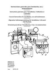
Fig. 18 A<br />
1<br />
5<br />
7<br />
1<br />
Fig. 11<br />
4<br />
3<br />
2<br />
6<br />
Fig.18B
CONJUNTO GENERAL / ENSEMBLE GENERAL<br />
GENERAL DIAGRAM / GESAMTANSICHT / INSIEME GENERALE<br />
GA-20 GA-40<br />
1 CORTATIRO 1 COUPE-TIRAGE 1 INTERRUTTORE<br />
DEL TIRAGGIO<br />
2 CUBIERTA KIT 2 CCAPOT KIT 2 CARCASSA KIT<br />
3 TECHO KIT 3 TOIT KIT 3 TETTO KIT<br />
4 TERMOSTATO<br />
SEGURIDAD<br />
4 THERMOSTAT<br />
SEGURIDAD<br />
2<br />
4 TERMOSTATO DI<br />
SICUREZZA<br />
5 EXTRACTOR 5 EXTRACTEUR 5 VENTOLA<br />
6 CONDUCCION 6 CONDUIT 6 CONDUTTURA<br />
7 TUBO EMPALME 7 CONDUIT D´UNION 7 TUBO RACCORDO<br />
1 DRAUGHT DIVERTER 1 LÜFTUNGSKLAPPE<br />
2 KIT COVER 2 ZUBEHÖRSATZ MANTEL<br />
3 KIT LID 3 ZUBEHÖRSATZ ABDECKUNG<br />
4 SAFETY THERMOSTAT 4 SICHERHEITSTHERMOSTAT<br />
5 EXTRACTOR 5 ABZUG<br />
6 PIPE 6 LEITUNG<br />
7 CONNECTION PIPE 7 VERBINDUNGSROHR
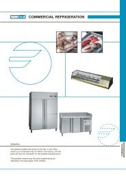
CONEXION TERMOSTATO SEGURIDAD-VENTILADOR<br />
RACCORDEMENT THERMOSTAT SECURITE-VENTILATEUR<br />
SAFETY THERMOSTAT-FAN CONNECTION<br />
VERBINDUNG ZWISCHEN SICHERHEITSTHERMOSTAT –<br />
VENTILATOR<br />
CONNESSIONE TERMOSTATO DI SICUREZZA – VENTOLA<br />
a<br />
2<br />
VE<br />
3<br />
1<br />
100<br />
Nº<br />
1<br />
2<br />
3<br />
4<br />
n<br />
Tsa<br />
4<br />
na<br />
100<br />
40mm 40mm<br />
20 20<br />
Color<br />
Couleur<br />
Colour<br />
Farbe<br />
Colore<br />
Negro<br />
Noir<br />
Black<br />
Schwarz<br />
Nero<br />
Azul<br />
Bleu<br />
Blue<br />
Blau<br />
Blu<br />
Negro<br />
Noir<br />
Black<br />
Schwarz<br />
Nero<br />
Naranja<br />
Orange<br />
Orange<br />
Orange<br />
Arancio<br />
1920<br />
mm²<br />
0,75<br />
3<br />
200<br />
1<br />
n<br />
VE<br />
200<br />
Longitud<br />
Longueur<br />
Length<br />
Länge<br />
Lunghezza<br />
2800<br />
2450<br />
a<br />
2<br />
200<br />
3<br />
Tsa<br />
n<br />
150<br />
Material<br />
Materiel<br />
Material<br />
Werkstoff<br />
Materiale<br />
na<br />
4<br />
Fibra vidrio<br />
Fibre de<br />
verre<br />
Fibre glass<br />
Glasfaser<br />
Vetroresina<br />
100
60<br />
90<br />
TM<br />
C<br />
rs<br />
L<br />
am<br />
ESQUEMA MONTAJE / SCHEMA MONTAGE<br />
ASSEMBLY DIAGRAM / MONTAGESCHALTBILD /<br />
180 150<br />
a<br />
vi<br />
92<br />
ve M<br />
VE<br />
Z-959512<br />
1<br />
vi g am<br />
am/ve<br />
P-453026<br />
ve<br />
R-073005 a<br />
r R-073005 n<br />
Z-263303<br />
n<br />
Tsa<br />
Z-959511<br />
1<br />
n<br />
Tc 90<br />
Z-953001<br />
1<br />
F=10A R-723015<br />
SCHEMA DI MONTAGGIO<br />
a<br />
m<br />
5<br />
4<br />
7<br />
3<br />
rs<br />
g<br />
a<br />
10<br />
6 ve DN<br />
r 2 1 r<br />
Cortatiro<br />
Z-953002<br />
R-743009<br />
R-343072<br />
1<br />
n<br />
Z-953036<br />
Tsdc Tsc<br />
m<br />
am<br />
b<br />
92<br />
b<br />
180<br />
na<br />
1<br />
L=180<br />
L=280<br />
r<br />
r<br />
A1 A1<br />
NC<br />
b NC<br />
rs<br />
n NA r<br />
Z-743009<br />
a<br />
g<br />
1 1<br />
Z-953050<br />
1<br />
1 R1<br />
1<br />
b<br />
a<br />
g<br />
NA+NC<br />
Z-953046<br />
1<br />
24h<br />
n<br />
24´<br />
g<br />
M1 rs<br />
DLL<br />
V<br />
CE<br />
5<br />
b<br />
Z-701135<br />
g<br />
a<br />
a<br />
am/ve<br />
SI<br />
na<br />
n<br />
BD<br />
PG<br />
Step<br />
a na m mvi b vi<br />
g<br />
A1 A2<br />
NO<br />
a<br />
Z-953017<br />
a<br />
1<br />
na<br />
n<br />
a<br />
T-303013<br />
Z-213007<br />
g<br />
b<br />
am<br />
GA-20 Z-953052<br />
GA-40 Z-963005<br />
R<br />
r<br />
1 b<br />
n<br />
Z-953051<br />
L=250<br />
1<br />
TM<br />
Cort a tiro<br />
Z-959535<br />
Lavavajillas<br />
Z-213033<br />
na<br />
vi<br />
Lr<br />
1<br />
na<br />
b<br />
Ir<br />
Esquema Adhesivo Z-953019<br />
Indicador de Componentes Z-953023<br />
1<br />
R-693055<br />
Lmp<br />
1<br />
ve<br />
g a<br />
R-693056<br />
Lc<br />
na mna<br />
b<br />
Tdc<br />
R-693056<br />
Ldc<br />
na<br />
1<br />
rs<br />
150<br />
ars<br />
T-113040<br />
Lsdc<br />
r<br />
ma<br />
Z-953035<br />
1 1
THE IMPORTANCE OF DESCALING<br />
If a significant amount of scale builds up inside the generator, the amber light will come on (5)<br />
(Fig. 11). If this happens, the warning limiter has to be reset, by pressing the reset button (7)<br />
(Fig. 11).<br />
After resetting the limiter, the inside of the generator has to be descaled, by following the<br />
process described <strong>for</strong> <strong>maintenance</strong>.<br />
If this cleaning process is not followed, there may be an excessive build up of scale inside the<br />
generator which will ca<strong>use</strong> the red light to come on (6) (Fig. 11) <strong>and</strong> the generator will go out of<br />
service.<br />
If this happens, you will need to call <strong>for</strong> Service.<br />
Generator <strong>maintenance</strong>.<br />
GENERATOR DESCALING PROCESS<br />
(It is recommended that the generator be cleaned at the end of the day so that the descaler has<br />
time to work overnight.)<br />
1. Turn off the dishwasher <strong>and</strong> turn off the generator gas stopcock.<br />
2. Empty the water from the generator by turning on the emptying tap (Fig. 18A).<br />
3. Turn off the tap <strong>and</strong> pour 5 litres of descaler in through the stainless steel tube <strong>and</strong> funnel<br />
provided (Fig. 18B).<br />
4. Switch on the dishwasher so that the generator fills up with water.<br />
5. Switch off the dishwasher <strong>and</strong> let the descaler work overnight.<br />
6. Empty the appliance by means of a rubber tube the following morning (Fig. 18A).<br />
7. Turn on the dishwasher with the emptying tap turned on <strong>and</strong> the end of the rubber tube<br />
connected to the drain. Ensure that the inside of the generator <strong>and</strong> the dishwasher are rinsed<br />
clean of descaler by means of a number of filling <strong>and</strong> emptying operations.<br />
6
FORCED DRAUGHT trans<strong>for</strong>mation accessory:<br />
FITTING INSTRUCTIONS<br />
The draught diverter fits directly in the generator flue <strong>and</strong> the draught<br />
diverter’s safety thermostat is electrically connected to the generator. The fan shall be<br />
fitted to the draught diverter outlet by means of the two screws supplied <strong>for</strong> that purpose<br />
<strong>and</strong> it is electrically connected to the generator by means of the “thermostat-fan<br />
connection” electrical <strong>installation</strong> supplied. This electrical <strong>installation</strong> should be<br />
connected as indicated in the assembly diagram.<br />
The fan shall be fitted to the draught diverter outlet by means of the two screws<br />
supplied <strong>for</strong> that purpose.<br />
Once the draught diverter has been installed, with the fan, the draught diverter<br />
outlet (or the fan outlet if fitted) shall be connected to the outside of the premises by<br />
means of a 110 mm diameter stainless steel enamelled pipe.<br />
HOW IT WORKS<br />
During normal operation of the hot water generator, the <strong>for</strong>ced draught<br />
accessory removes the combustion fumes, expelling them outside the premises where it<br />
is installed.<br />
If any problem occurs with the extraction of the combustion fumes, <strong>for</strong><br />
example, an obstruction in the pipe resulting in incorrect draught conditions in the flue,<br />
the draught diverter’s safety thermostat will overheat <strong>and</strong> reach 90ºC in less than 2<br />
minutes, cutting off the supply of gas to the burner <strong>and</strong> thereby, switching off the<br />
appliance.<br />
The safety thermostat will automatically reset after 10 minutes. If the bad<br />
draught conditions in the flue persist, the safety thermostat will be activated again <strong>and</strong><br />
switch off the generator. If the interruptions continue, it is recommended that you call<br />
<strong>for</strong> service.<br />
The functional parts, like the safety thermostat, should not be h<strong>and</strong>led by the<br />
fitter or the <strong>use</strong>r. Defective parts must only be replaced by original spare parts. This<br />
work must be carried out by a specialist engineer.<br />
7