Installation instructions for Fabspeed Valvetronic Mufflers Vacuum ...
Installation instructions for Fabspeed Valvetronic Mufflers Vacuum ...
Installation instructions for Fabspeed Valvetronic Mufflers Vacuum ...

You also want an ePaper? Increase the reach of your titles
YUMPU automatically turns print PDFs into web optimized ePapers that Google loves.
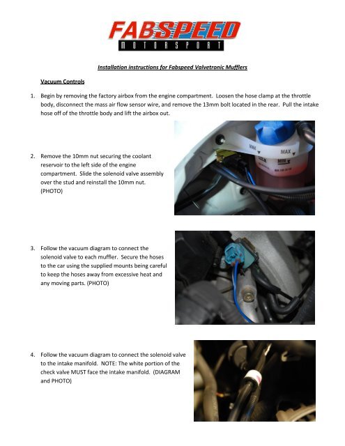
<strong>Vacuum</strong> Controls<br />
<strong>Installation</strong> <strong>instructions</strong> <strong>for</strong> <strong>Fabspeed</strong> <strong>Valvetronic</strong> <strong>Mufflers</strong><br />
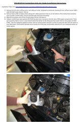
1. Begin by removing the factory airbox from the engine compartment. Loosen the hose clamp at the throttle<br />
body, disconnect the mass air flow sensor wire, and remove the 13mm bolt located in the rear. Pull the intake<br />
hose off of the throttle body and lift the airbox out.<br />
2. Remove the 10mm nut securing the coolant<br />
reservoir to the left side of the engine<br />
compartment. Slide the solenoid valve assembly<br />
over the stud and reinstall the 10mm nut.<br />
(PHOTO)<br />
3. Follow the vacuum diagram to connect the<br />
solenoid valve to each muffler. Secure the hoses<br />
to the car using the supplied mounts being careful<br />
to keep the hoses away from excessive heat and<br />
any moving parts. (PHOTO)<br />
4. Follow the vacuum diagram to connect the solenoid valve<br />
to the intake manifold. NOTE: The white portion of the<br />
check valve MUST face the intake manifold. (DIAGRAM<br />
and PHOTO)
Electronic Controls<br />
1. Place the convertible top into the service position. Open the top until the boot cover is up approx. 8”.<br />
Disconnect the cables at each end and fold the rear glass up out of the way.<br />
2. Remove the four plastic retaining clips from the trim panel and remove the trim panel from the car.<br />
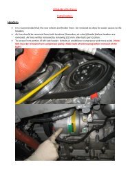
3. The rear relay/fuse panel is now visible behind the rear seat. Lift up the sound deadening under the relay panel<br />
on the left side and remove the rubber body plug beneath it (PHOTO). Cut a small hole in the plug (approx<br />
.125”) and snap back into place.<br />
4. Feed the BLUE and BLACK/WHITE wires through the hole into the engine compartment. Snap the black plastic<br />
connector onto the wires according the wire diagram (observe polarity!) and plug the connector into the<br />
solenoid valve.<br />
5. Secure the wires away from excessive heat or any moving parts using wire ties.<br />
6. Connect the red wire to a 12volt battery source at the relay panel. (Consult your vehicle’s specific wiring diagram<br />
to locate a suitable source.)<br />
7. Connect the black wire to a clean ground location<br />
(PHOTO).<br />
8. Mount the receiver box in a suitable location near the relay<br />
panel using either double-sided tape or the mounting tabs.<br />
9. Connect the white 12pin connector into the receiver.<br />
Final Assembly and testing<br />
1. Reinstall airbox and plug in mass air flow sensor.<br />
Double check all wires and hoses <strong>for</strong> interference and tight connections.<br />
2. With key on press “open” or “close” button on remote and listen to the solenoid valve. There should be an<br />
audible “click” when activated.<br />
3. Start engine, let idle and double check <strong>for</strong> vacuum leaks caused by loose hoses.<br />
4. Press “Open” or “Close” button on remote to open or close valves. A significant change in exhaust note<br />
should be heard.