
Create successful ePaper yourself
Turn your PDF publications into a flip-book with our unique Google optimized e-Paper software.
PREFACE<br />
Rev. 02 of the 20/02/2013<br />
Carbon Sequential Gear – <strong>User</strong> <strong>Manual</strong><br />
To take advantage of the features of your product and<br />
protect it from malfunction and/or damage damage, read this<br />
document carefully.<br />
By purchasing this product you agree to the terms<br />
contained in the warranty.<br />
ATTENTION<br />
The opening of the hardware made by<br />
unauthorized personnel, with the consequent<br />
breaking of the warranty seals seals, makes void the<br />
warranty.<br />
Note: the pictures may differ slightly from the product in<br />
your possession. <strong>ARC</strong>_<strong>Team</strong> also reserves the right to<br />
modify and/or adapt shapes, sizes and technical content of<br />
the product without prior notice.<br />
CAUTION<br />
Keep the product out of the reach of children, pets pets, liquids,<br />
moisture and heat above 54 ° C. Use this product indoors<br />
only.<br />
COMPONENTS LIST<br />
- Carbon Sequential Gear<br />
- Lever extension<br />
- Handles<br />
- Sparco’s knob (optional)<br />
- Clamp (optional)<br />
- Lobe knob (optional)<br />
- USB cable (only on “USB” ” type model model)<br />
LOOSEN TIGHTEN<br />
FIG. 1<br />
MOUNTING<br />
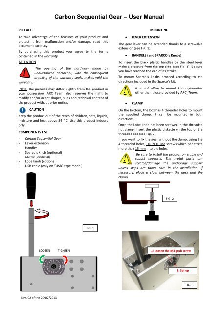
• LEVER EXTENSION<br />
The gear lever can be extended thanks to a screwable<br />
extension (see Fig. 1).<br />
• HANDELS (and SP<strong>ARC</strong>O SP<strong>ARC</strong>O’s Knobs)<br />
To insert the black plastic handles on the steel lever<br />
make a pressure from the top side (see Fig. 1). Be sure<br />
you have reached the end of its stroke.<br />
To mount Sparco’s knobs s proceed according to the<br />
directions included in the Sparco’ Sparco’s kit.<br />
• CLAMP<br />
It is not allow to mount knobbs/handkes<br />
other than those provided by <strong>ARC</strong>_<strong>Team</strong>.<br />
On the bottom, the box has 4 threaded holes to mount<br />
the supplied clamp. It ca can be mounted in both<br />
directions.<br />
Once the Lobe knob has been screwed in the threaded<br />
nut clamp, insert the plastic diskette on the top of the<br />
threaded rod (see Fig. 2)<br />
If you want to fix the gear without the clamp clamp, using the<br />
4 threaded holes, DO NOT use screws which penetrate<br />
more than 15 mm into the holes holes.<br />
Be sure to install the product on stable and<br />
robust supports. The metal parts can<br />
scratch/damage the anchorage support<br />
unless steps are taken care in the installation. If<br />
necessary, place a cloth between the desk and the<br />
clamp.<br />
FIG. 2<br />
1: Loose Loosen the M3 grub screw<br />
2: Set up<br />
FIG. 3
USB CONNECTION<br />
The USB cable must be connected directly to one of the<br />
USB mother board ports of the PC, keeping free the<br />
USB port next to that just used by the cable cable.<br />
Rev. 02 of the 20/02/2013<br />
Do not connect the USB cable to an external<br />
HUB or to the USB ports of the PC cabinet cabinet.<br />
Note: for the configuration without electronics electronics, a cable<br />
for interfacing the gear micro-switches switches to the pcb<br />
joystick controller pins is provided provided. The customer<br />
should arrange for connecting the wires wires, taking care to<br />
consider the colors:<br />
or common<br />
switch A<br />
switch B<br />
DATA<br />
- Dimensions (mm): : length 176 mm, width 50 mm,<br />
height with the extension (excluding handles and<br />
clamp) 190 mm<br />
- Gear weight (kg): 1<br />
- Clamp weight (Kg): 0,5<br />
- Spring plungers force (N): from 57 to 104<br />
- Moment of the force on the lever (Nm): : from 0 to 9<br />
- Power supply: USB<br />
- Clamp span (mm): from 0 to 40<br />
<strong>ARC</strong>_<strong>Team</strong> srl<br />
SETTINGS<br />
Carbon Sequential Gear mounts a couple of adjustable<br />
hardened steel spring plungers plungers. It is possible to<br />
increase/decrease the gear lever resistance by<br />
tightening up or loosening the spring plungers placed<br />
on the sides of the box, in the positive positive/negative sense<br />
shown by the two colored arrows (see Fig. 1). Use a<br />
suitable Allen key in order to setup the resistance,<br />
inserting it inside the Allen spring plungers heads heads, not<br />
before loosening the M3 grub screws placed on the<br />
two nuts where the plungers are screwed (see Fig. 3).<br />
Do not tighten up overly the plungers, in<br />
order to avoid the lever blocking blocking. The<br />
rotation degree in one direction or another<br />
must always be identical on both sides (refer to the<br />
notches). Do not loosen or tighten the external 18 mm<br />
nuts, where the Allen spring plungers are screwed.<br />
Sede Legale e Operativa: V.le Brambilla, 98 – 27100 Pavia (ITALY)<br />
Tel. +39 0382 528079 | Fax +39 0382 520167 | Website http://www.f1driving.it | E--mail<br />
info@f1driving.it