CrossPoint 300 84 HV/HVA - Extron Electronics
CrossPoint 300 84 HV/HVA - Extron Electronics
CrossPoint 300 84 HV/HVA - Extron Electronics

Create successful ePaper yourself
Turn your PDF publications into a flip-book with our unique Google optimized e-Paper software.
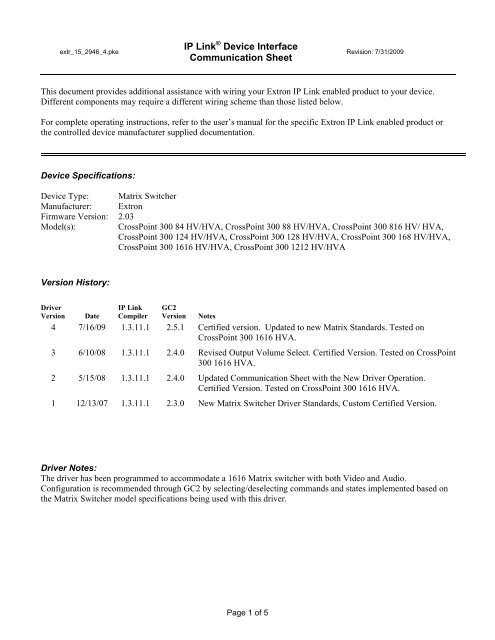
extr_15_2946_4.pke<br />
IP Link ® Device Interface<br />
Communication Sheet<br />
Page 1 of 5<br />
Revision: 7/31/2009<br />
This document provides additional assistance with wiring your <strong>Extron</strong> IP Link enabled product to your device.<br />
Different components may require a different wiring scheme than those listed below.<br />
For complete operating instructions, refer to the user’s manual for the specific <strong>Extron</strong> IP Link enabled product or<br />
the controlled device manufacturer supplied documentation.<br />
Device Specifications:<br />
Device Type: Matrix Switcher<br />
Manufacturer: <strong>Extron</strong><br />
Firmware Version: 2.03<br />
Model(s): <strong>CrossPoint</strong> <strong>300</strong> <strong>84</strong> <strong>HV</strong>/<strong>HV</strong>A, <strong>CrossPoint</strong> <strong>300</strong> 88 <strong>HV</strong>/<strong>HV</strong>A, <strong>CrossPoint</strong> <strong>300</strong> 816 <strong>HV</strong>/ <strong>HV</strong>A,<br />
<strong>CrossPoint</strong> <strong>300</strong> 124 <strong>HV</strong>/<strong>HV</strong>A, <strong>CrossPoint</strong> <strong>300</strong> 128 <strong>HV</strong>/<strong>HV</strong>A, <strong>CrossPoint</strong> <strong>300</strong> 168 <strong>HV</strong>/<strong>HV</strong>A,<br />
<strong>CrossPoint</strong> <strong>300</strong> 1616 <strong>HV</strong>/<strong>HV</strong>A, <strong>CrossPoint</strong> <strong>300</strong> 1212 <strong>HV</strong>/<strong>HV</strong>A<br />
Version History:<br />
Driver<br />
Version<br />
Date<br />
IP Link<br />
Compiler<br />
GC2<br />
Version<br />
Notes<br />
4 7/16/09 1.3.11.1 2.5.1 Certified version. Updated to new Matrix Standards. Tested on<br />
<strong>CrossPoint</strong> <strong>300</strong> 1616 <strong>HV</strong>A.<br />
3 6/10/08 1.3.11.1 2.4.0 Revised Output Volume Select. Certified Version. Tested on <strong>CrossPoint</strong><br />
<strong>300</strong> 1616 <strong>HV</strong>A.<br />
2 5/15/08 1.3.11.1 2.4.0 Updated Communication Sheet with the New Driver Operation.<br />
Certified Version. Tested on <strong>CrossPoint</strong> <strong>300</strong> 1616 <strong>HV</strong>A.<br />
1 12/13/07 1.3.11.1 2.3.0 New Matrix Switcher Driver Standards, Custom Certified Version.<br />
Driver Notes:<br />
The driver has been programmed to accommodate a 1616 Matrix switcher with both Video and Audio.<br />
Configuration is recommended through GC2 by selecting/deselecting commands and states implemented based on<br />
the Matrix Switcher model specifications being used with this driver.
extr_15_2946_4.pke<br />
Control Commands & States:<br />
IP Link ® Device Interface<br />
Communication Sheet<br />
Audio Mute 1-16 On Off<br />
Executive Mode Mode 1 Mode 2 Off<br />
Global Audio Mute On Off<br />
Input 1 - 16 Break<br />
Output 1 - 16<br />
Preset 1 - 16<br />
Page 2 of 5<br />
Revision: 7/31/2009<br />
Take Audio Video Audio-Video<br />
Volume 1-16 (Step) Up Down<br />
Volume 1- 16 (Discrete) 0 to 64<br />
Status Available:<br />
Audio Mute 1-16 On Off<br />
Connection Status Connected Disconnected<br />
Executive Mode Mode 1 Mode 2 Off<br />
Status Matrix routes indexed by output<br />
Volume 1- 16 (Discrete) 0 to 64<br />
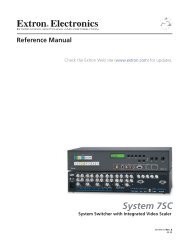
MLC62 Supported Commands:<br />
Audio Mute 1-16 On Off<br />
Executive Mode Mode 1 Mode 2 Off<br />
Global Audio Mute On Off
extr_15_2946_4.pke<br />
IP Link ® Device Interface<br />
Communication Sheet<br />
Page 3 of 5<br />
Revision: 7/31/2009<br />
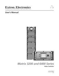
Matrix Driver Operation:<br />
Configuring input output(s) ties on a single button:<br />
This section will describe how to configure a MLC front panel button with either a single input and output tie or single<br />
input to multiple output ties. Please note that there are a minimum of three selections required when configuring a tie in<br />
this method.<br />
To configure a MLC front panel button with a single input and a single output tie follow the steps below.<br />
1. Select the desired input from the “input” command.<br />
2. Select the desired output from the “output” command.<br />
3. Select the type of desired take from the “take” command.<br />
To configure a MLC front panel button with multiple inputs and outputs repeat the steps above then follow the steps<br />
below.<br />
1. Insert a one second delay.<br />
2. Select the next desired output from the “output” command.<br />
3. Select the next desired take from the “take” command.<br />
4. Repeat as many times as desired.<br />
Below is an example of multiple ties configured on input button 1.
extr_15_2946_4.pke<br />
IP Link ® Device Interface<br />
Communication Sheet<br />
Page 4 of 5<br />
Revision: 7/31/2009<br />
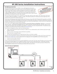
Configuring for direct matrix front panel emulation:<br />
This section will describe how to configure a MLC front panel to produce an input output selection capability.<br />
To configure a MLC front panel button input, create the following button operation.<br />
1. Select the desired input from the “input” command.<br />
To configure a MLC front panel button output, create the following button operations.<br />
1. Select the desired output from the “output” command.<br />
2. Select the desired take from the “take” command.<br />
Below is an example of the output button configuration.
extr_15_2946_4.pke<br />
IP Link ® Device Interface<br />
Communication Sheet<br />
Cable and Adapter Requirements:<br />
M/F RS-232 straight serial cable (<strong>Extron</strong> <strong>Electronics</strong> P/N 26-433-XX)<br />
Notes for the Device:<br />
Serial communication:<br />
Port Type: RS232 Parity: None<br />
Baud Rate: 9600 Stop Bits: 1<br />
Data Bits: 8 Flow Control: None<br />
Pin Assignments Diagram:<br />
Note: Captive screw connector may also be used as a serial connection.<br />
General Notes:<br />
Page 5 of 5<br />
Revision: 7/31/2009