DVI 104 Tx/Rx User's Guide - Extron Electronics
DVI 104 Tx/Rx User's Guide - Extron Electronics
DVI 104 Tx/Rx User's Guide - Extron Electronics

Create successful ePaper yourself
Turn your PDF publications into a flip-book with our unique Google optimized e-Paper software.
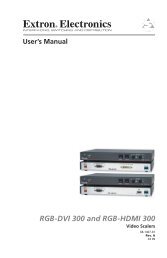
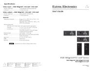
User’s <strong>Guide</strong><br />
<strong>DVI</strong> <strong>104</strong> <strong>Tx</strong>/<strong>Rx</strong><br />
<strong>DVI</strong> Fiber Optic Extender<br />
68-1549-01<br />
Rev. C<br />
10 08
Precautions<br />
Safety Instructions • English<br />
This symbol is intended to alert the user of important<br />
operating and maintenance (servicing) instructions in<br />
the literature provided with the equipment.<br />
This symbol is intended to alert the user of the<br />
presence of uninsulated dangerous voltage within<br />
the product’s enclosure that may present a risk of<br />
electric shock.<br />
Caution<br />
Read Instructions • Read and understand all safety and operating<br />
instructions before using the equipment.<br />
Retain Instructions • The safety instructions should be kept for future<br />
reference.<br />
Follow Warnings • Follow all warnings and instructions marked on the<br />
equipment or in the user information.<br />
Avoid Attachments • Do not use tools or attachments that are not<br />
recommended by the equipment manufacturer because they may be<br />
hazardous.<br />
Consignes de Sécurité • Français<br />
Ce symbole sert à avertir l’utilisateur que la<br />
documentation fournie avec le matériel contient des<br />
instructions importantes concernant l’exploitation et<br />
la maintenance (réparation).<br />
Ce symbole sert à avertir l’utilisateur de la présence<br />
dans le boîtier de l’appareil de tensions dangereuses<br />
non isolées posant des risques d’électrocution.<br />
Attention<br />
Lire les instructions• Prendre connaissance de toutes les consignes de<br />
sécurité et d’exploitation avant d’utiliser le matériel.<br />
Conserver les instructions• Ranger les consignes de sécurité afin de pouvoir<br />
les consulter à l’avenir.<br />
Respecter les avertissements • Observer tous les avertissements et consignes<br />
marqués sur le matériel ou présentés dans la documentation utilisateur.<br />
Eviter les pièces de fixation • Ne pas utiliser de pièces de fixation ni d’outils<br />
non recommandés par le fabricant du matériel car cela risquerait de poser<br />
certains dangers.<br />
Sicherheitsanleitungen • Deutsch<br />
Dieses Symbol soll dem Benutzer in der im<br />
Lieferumfang enthaltenen Dokumentation<br />
besonders wichtige Hinweise zur Bedienung und<br />
Wartung (Instandhaltung) geben.<br />
Dieses Symbol soll den Benutzer darauf aufmerksam<br />
machen, daß im Inneren des Gehäuses dieses<br />
Produktes gefährliche Spannungen, die nicht isoliert<br />
sind und die einen elektrischen Schock verursachen<br />
können, herrschen.<br />
Achtung<br />
Lesen der Anleitungen • Bevor Sie das Gerät zum ersten Mal verwenden,<br />
sollten Sie alle Sicherheits-und Bedienungsanleitungen genau durchlesen<br />
und verstehen.<br />
Aufbewahren der Anleitungen • Die Hinweise zur elektrischen Sicherheit<br />
des Produktes sollten Sie aufbewahren, damit Sie im Bedarfsfall darauf<br />
zurückgreifen können.<br />
Befolgen der Warnhinweise • Befolgen Sie alle Warnhinweise und<br />
Anleitungen auf dem Gerät oder in der Benutzerdokumentation.<br />
Keine Zusatzgeräte • Verwenden Sie keine Werkzeuge oder Zusatzgeräte,<br />
die nicht ausdrücklich vom Hersteller empfohlen wurden, da diese eine<br />
Gefahrenquelle darstellen können.<br />
Instrucciones de seguridad • Español<br />
Este símbolo se utiliza para advertir al usuario<br />
sobre instrucciones importantes de operación y<br />
mantenimiento (o cambio de partes) que se desean<br />
destacar en el contenido de la documentación<br />
suministrada con los equipos.<br />
Este símbolo se utiliza para advertir al usuario sobre<br />
la presencia de elementos con voltaje peligroso sin<br />
protección aislante, que puedan encontrarse dentro<br />
de la caja o alojamiento del producto, y que puedan<br />
representar riesgo de electrocución.<br />
Precaucion<br />
Leer las instrucciones • Leer y analizar todas las instrucciones de operación y<br />
seguridad, antes de usar el equipo.<br />
Conservar las instrucciones • Conservar las instrucciones de seguridad para<br />
futura consulta.<br />
Obedecer las advertencias • Todas las advertencias e instrucciones marcadas<br />
en el equipo o en la documentación del usuario, deben ser obedecidas.<br />
Evitar el uso de accesorios • No usar herramientas o accesorios que no<br />
sean especificamente recomendados por el fabricante, ya que podrian<br />
implicar riesgos.<br />
Warning<br />
Power sources • This equipment should be operated only from the power source<br />
indicated on the product. This equipment is intended to be used with a main power<br />
system with a grounded (neutral) conductor. The third (grounding) pin is a safety<br />
feature, do not attempt to bypass or disable it.<br />
Power disconnection • To remove power from the equipment safely, remove all power<br />
cords from the rear of the equipment, or the desktop power module (if detachable),<br />
or from the power source receptacle (wall plug).<br />
Power cord protection • Power cords should be routed so that they are not likely to be<br />
stepped on or pinched by items placed upon or against them.<br />
Servicing • Refer all servicing to qualified service personnel. There are no userserviceable<br />
parts inside. To prevent the risk of shock, do not attempt to service<br />
this equipment yourself because opening or removing covers may expose you to<br />
dangerous voltage or other hazards.<br />
Slots and openings • If the equipment has slots or holes in the enclosure, these are<br />
provided to prevent overheating of sensitive components inside. These openings<br />
must never be blocked by other objects.<br />
Lithium battery • There is a danger of explosion if battery is incorrectly<br />
replaced. Replace it only with the same or equivalent type recommended by<br />
the manufacturer. Dispose of used batteries according to the manufacturer’s<br />
instructions.<br />
Avertissement<br />
Alimentations• Ne faire fonctionner ce matériel qu’avec la source d’alimentation<br />
indiquée sur l’appareil. Ce matériel doit être utilisé avec une alimentation principale<br />
comportant un fil de terre (neutre). Le troisième contact (de mise à la terre) constitue<br />
un dispositif de sécurité : n’essayez pas de la contourner ni de la désactiver.<br />
Déconnexion de l’alimentation• Pour mettre le matériel hors tension sans danger,<br />
déconnectez tous les cordons d’alimentation de l’arrière de l’appareil ou du module<br />
d’alimentation de bureau (s’il est amovible) ou encore de la prise secteur.<br />
Protection du cordon d’alimentation • Acheminer les cordons d’alimentation de<br />
manière à ce que personne ne risque de marcher dessus et à ce qu’ils ne soient pas<br />
écrasés ou pincés par des objets.<br />
Réparation-maintenance • Faire exécuter toutes les interventions de réparationmaintenance<br />
par un technicien qualifié. Aucun des éléments internes ne peut être<br />
réparé par l’utilisateur. Afin d’éviter tout danger d’électrocution, l’utilisateur ne doit<br />
pas essayer de procéder lui-même à ces opérations car l’ouverture ou le retrait des<br />
couvercles risquent de l’exposer à de hautes tensions et autres dangers.<br />
Fentes et orifices • Si le boîtier de l’appareil comporte des fentes ou des orifices, ceux-ci<br />
servent à empêcher les composants internes sensibles de surchauffer. Ces ouvertures<br />
ne doivent jamais être bloquées par des objets.<br />
Lithium Batterie • Il a danger d’explosion s’ll y a remplacment incorrect de la batterie.<br />
Remplacer uniquement avec une batterie du meme type ou d’un ype equivalent<br />
recommande par le constructeur. Mettre au reut les batteries usagees conformement<br />
aux instructions du fabricant.<br />
Vorsicht<br />
Stromquellen • Dieses Gerät sollte nur über die auf dem Produkt angegebene<br />
Stromquelle betrieben werden. Dieses Gerät wurde für eine Verwendung mit einer<br />
Hauptstromleitung mit einem geerdeten (neutralen) Leiter konzipiert. Der dritte<br />
Kontakt ist für einen Erdanschluß, und stellt eine Sicherheitsfunktion dar. Diese<br />
sollte nicht umgangen oder außer Betrieb gesetzt werden.<br />
Stromunterbrechung • Um das Gerät auf sichere Weise vom Netz zu trennen, sollten<br />
Sie alle Netzkabel aus der Rückseite des Gerätes, aus der externen Stomversorgung<br />
(falls dies möglich ist) oder aus der Wandsteckdose ziehen.<br />
Schutz des Netzkabels • Netzkabel sollten stets so verlegt werden, daß sie nicht im<br />
Weg liegen und niemand darauf treten kann oder Objekte darauf- oder unmittelbar<br />
dagegengestellt werden können.<br />
Wartung • Alle Wartungsmaßnahmen sollten nur von qualifiziertem Servicepersonal<br />
durchgeführt werden. Die internen Komponenten des Gerätes sind wartungsfrei.<br />
Zur Vermeidung eines elektrischen Schocks versuchen Sie in keinem Fall, dieses<br />
Gerät selbst öffnen, da beim Entfernen der Abdeckungen die Gefahr eines<br />
elektrischen Schlags und/oder andere Gefahren bestehen.<br />
Schlitze und Öffnungen • Wenn das Gerät Schlitze oder Löcher im Gehäuse aufweist,<br />
dienen diese zur Vermeidung einer Überhitzung der empfindlichen Teile im<br />
Inneren. Diese Öffnungen dürfen niemals von anderen Objekten blockiert werden.<br />
Litium-Batterie • Explosionsgefahr, falls die Batterie nicht richtig ersetzt<br />
wird. Ersetzen Sie verbrauchte Batterien nur durch den gleichen oder einen<br />
vergleichbaren Batterietyp, der auch vom Hersteller empfohlen wird. Entsorgen Sie<br />
verbrauchte Batterien bitte gemäß den Herstelleranweisungen.<br />
Advertencia<br />
Alimentación eléctrica • Este equipo debe conectarse únicamente a la fuente/tipo<br />
de alimentación eléctrica indicada en el mismo. La alimentación eléctrica de este<br />
equipo debe provenir de un sistema de distribución general con conductor neutro<br />
a tierra. La tercera pata (puesta a tierra) es una medida de seguridad, no puentearia<br />
ni eliminaria.<br />
Desconexión de alimentación eléctrica • Para desconectar con seguridad la acometida<br />
de alimentación eléctrica al equipo, desenchufar todos los cables de alimentación<br />
en el panel trasero del equipo, o desenchufar el módulo de alimentación (si fuera<br />
independiente), o desenchufar el cable del receptáculo de la pared.<br />
Protección del cables de alimentación • Los cables de alimentación eléctrica se deben<br />
instalar en lugares donde no sean pisados ni apretados por objetos que se puedan<br />
apoyar sobre ellos.<br />
Reparaciones/mantenimiento • Solicitar siempre los servicios técnicos de personal<br />
calificado. En el interior no hay partes a las que el usuario deba acceder. Para evitar<br />
riesgo de electrocución, no intentar personalmente la reparación/mantenimiento<br />
de este equipo, ya que al abrir o extraer las tapas puede quedar expuesto a voltajes<br />
peligrosos u otros riesgos.<br />
Ranuras y aberturas • Si el equipo posee ranuras o orificios en su caja/alojamiento,<br />
es para evitar el sobrecalientamiento de componentes internos sensibles. Estas<br />
aberturas nunca se deben obstruir con otros objetos.<br />
Batería de litio • Existe riesgo de explosión si esta batería se coloca en la posición<br />
incorrecta. Cambiar esta batería únicamente con el mismo tipo (o su equivalente)<br />
recomendado por el fabricante. Desachar las baterías usadas siguiendo las<br />
instrucciones del fabricante.
安全须知 • 中文<br />
这个符号提示用户该设备用户手册中<br />
有重要的操作和维护说明。<br />
这个符号警告用户该设备机壳内有暴<br />
露的危险电压,有触电危险。<br />
注意<br />
阅读说明书 • 用户使用该设备前必须阅读并理<br />
解所有安全和使用说明。<br />
保存说明书 • 用户应保存安全说明书以备将来使<br />
用。<br />
遵守警告 • 用户应遵守产品和用户指南上的所有安<br />
全和操作说明。<br />
避免追加 • 不要使用该产品厂商没有推荐的工具或<br />
追加设备,以避免危险。<br />
声明<br />
警告<br />
电源 • 该设备只能使用产品上标明的电源。 设备<br />
必须使用有地线的供电系统供电。 第三条线<br />
(地线)是安全设施,不能不用或跳过。<br />
拔掉电源 • 为安全地从设备拔掉电源,请拔掉所有设备后<br />
或桌面电源的电源线,或任何接到市电系统的电源线。<br />
电源线保护 • 妥善布线, 避免被踩踏,或重物挤压。<br />
维护 • 所有维修必须由认证的维修人员进行。 设备内部<br />
没有用户可以更换的零件。为避免出现触电危险不要自<br />
己试图打开设备盖子维修该设备。<br />
通风孔 • 有些设备机壳上有通风槽或孔,它们是用来防止<br />
机内敏感元件过热。 不要用任何东西挡住通风孔。<br />
锂电池 • 不正确的更换电池会有爆炸的危险。 必须使用<br />
与厂家推荐的相同或相近型号的电池。 按照生产厂的<br />
建议处理废弃电池。<br />
所使用电源为 A 级产品,在生活环境中,该产品可能会造成无线电干扰。在这种情况下,可能需要用<br />
户对其干扰采取切实可行的措施。<br />
FCC Class A Notice<br />
This equipment has been tested and found to comply with the limits for a Class A digital device,<br />
pursuant to part 15 of the FCC Rules. Operation is subject to the following two conditions: (1) this<br />
device may not cause harmful interference, and (2) this device must accept any interference received,<br />
including interference that may cause undesired operation. The Class A limits are designed to<br />
provide reasonable protection against harmful interference when the equipment is operated in<br />
a commercial environment. This equipment generates, uses, and can radiate radio frequency<br />
energy and, if not installed and used in accordance with the instruction manual, may cause harmful<br />
interference to radio communications. Operation of this equipment in a residential area is likely to<br />
cause harmful interference, in which case the user will be required to correct the interference at his<br />
own expense.<br />
N This unit was tested with shielded cables on the peripheral devices. Shielded cables must be used<br />
with the unit to ensure compliance with FCC emissions limits.<br />
68-1549-01<br />
Rev. C<br />
10 08
<strong>DVI</strong> <strong>104</strong> <strong>Tx</strong>/<strong>Rx</strong><br />
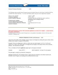
Description<br />
The <strong>DVI</strong> <strong>104</strong> <strong>Tx</strong> and <strong>DVI</strong> <strong>104</strong> <strong>Rx</strong> are fiber optic transmitter/<br />
receiver units that extend <strong>DVI</strong> signals up to 1,640' (500 m) using<br />
four multimode fiber optics cables.<br />
The transmitter plugs directly into the source device and the<br />
receiver plugs directly into the display device.<br />
The transmitter/receiver pair can handle <strong>DVI</strong> video signals with<br />
resolutions up to 1920 x 1200 or 1080p @ 60 Hz.<br />
Optional four-fiber multimode cables are available in varying<br />
lengths.<br />
PC with <strong>DVI</strong> Output<br />
<strong>DVI</strong> <strong>104</strong><br />
Transmitter<br />
4 Multi Mode<br />
Fiber<br />
Up to 500 m (1640')<br />
Hi-resolution<br />
Flat Panel Display<br />
with <strong>DVI</strong>-D Input<br />
<strong>DVI</strong> <strong>104</strong><br />
Receiver<br />
<strong>DVI</strong> <strong>104</strong> <strong>Tx</strong>/<strong>Rx</strong> • User’s <strong>Guide</strong><br />
1
<strong>DVI</strong> <strong>104</strong> <strong>Tx</strong>/<strong>Rx</strong>, cont’d<br />
2<br />
Features<br />
Power Supply — Separate power supplies are provided for both<br />
the transmitter and receiver.<br />
Power LEDs — The LEDs are on the top and bottom panels of<br />
both the receiver and transmitter. They illuminate blue when<br />
the unit is receiving power.<br />
No mounting hardware required — The units plug directly into<br />
the source device (transmitter) or output device (receiver) and<br />
take up very little space.<br />
EDID Minder — The <strong>DVI</strong> <strong>104</strong> transmitter is able to capture<br />
and store the display device’s resolution and refresh rate, which<br />
ensures that the source boots up with the correct resolution.<br />
Long cable runs — The <strong>DVI</strong> <strong>104</strong> <strong>Tx</strong>/<strong>Rx</strong> uses four fiber optic<br />
cables to extend video signals up to 1640' (500 m). The cables<br />
must be either 62.5/125 multimode cable or 50/125 multimode<br />
cable.<br />
High resolution signal transmission — The units transmit<br />
signals at resolutions up to 1920 x 1200 or 1080p @ 60 Hz.<br />
High rate of data transfer — The units can transmit signals at<br />
up to 1.65 Gbps<br />
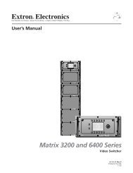
Front panel features<br />
a<br />
1 2<br />
Power input — The transmitter and receiver both have plugs for<br />
a 3.5 mm jack to provide 5 VDC to the unit.<br />
The center pin of the jack carries +5 VDC; the outer shell of the<br />
jack is the negative rail.<br />
N If the source device is able to provide 5 VDC on pin 14<br />
of its <strong>DVI</strong> output, the transmitter can draw power from<br />
the source device. If the source is a laptop or a PC using<br />
a PCI-E graphics card, it will not be able to provide<br />
enough power and the transmitter must be powered with<br />
a separate external power supply.<br />
<strong>DVI</strong> <strong>104</strong> <strong>Tx</strong>/<strong>Rx</strong> • User’s <strong>Guide</strong><br />
The receiver must be powered by an external power<br />
supply through the power input plug.
LC Jacks — Four fiber optic cables connect the transmitter to the<br />
receiver. The cables connect to the four female LC jacks in each<br />
of the units.<br />
A label on the top panel identifies the unit as the transmitter<br />
or receiver and identifies the fiber optic port numbers and the<br />
power input.<br />
N For the transmitter, port 1 is closest to the power input<br />
and port 4 is furthest away. For the receiver, port 4 is<br />
closest to the power input and port 1 is furthest away.<br />
Although the orientation is reversed, ports with the<br />
same number must be connected by the same cable, so<br />
that port 1 on the receiver is connected to port 1 on the<br />
transmitter, etc.<br />
Insert the end of the fiber optic cable into the appropriate plug<br />
on the transmitter or receiver. The locking catch should snap<br />
into the slot and hold the cable securely in place.<br />
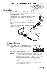
If the cable is loose or slips out of the slot easily, move the<br />
release catch from its normal position above the locking catch,<br />
to the adjusted position under the locking catch (see the figure<br />
below). This provides the extra leverage required to keep the<br />
locking catch in place and hold the cable securely.<br />
Locking catch Release catch<br />
Normal Position<br />
Adjusted Position<br />
<strong>DVI</strong> <strong>104</strong> <strong>Tx</strong>/<strong>Rx</strong> • User’s <strong>Guide</strong><br />
3
<strong>DVI</strong> <strong>104</strong> <strong>Tx</strong>/<strong>Rx</strong>, cont’d<br />
4<br />
Rear panel features<br />
c<br />
3<br />
9<br />
1 3 6 8<br />
17 19 22 24<br />
<strong>DVI</strong> <strong>104</strong> <strong>Tx</strong>/<strong>Rx</strong> • User’s <strong>Guide</strong><br />
Male Connector<br />
A single-link <strong>DVI</strong>-D male connector is used to connect the<br />
transmitter to the source and the receiver to the output device.<br />
Pin Signal Pin Signal Pin Signal<br />
1 TMDS data 2- 9 TMDS data 1- 17 TMDS data 0-<br />
2 TMDS data 2+ 10 TMDS data 1+ 18 TMDS data 0+<br />
3 TMDS data 2<br />
shield<br />
11 TMDS data 1<br />
shield<br />
19 TMDS data 0<br />
shield<br />
6 DDC clock 14 +5 V power 22 TMDS clock<br />
shield<br />
7 DDC data 15 Ground (+5V) 23 TMDS clock+<br />
8 CEC control 16 Hot plug<br />
detect<br />
Top panel features<br />
d<br />
e<br />
4 5<br />
24 TMDD clock -<br />
LED — Both the transmitter and receiver have LEDs on<br />
the top and bottom panels that light blue when the unit is<br />
receiving power. The LEDs on the transmitter also functions as<br />
a status indicator for the EDID minder feature (see “Setup and<br />
Operation”).<br />
Thumbscrews — Use the thumbscrews to secure the transmitter<br />
or receiver to its connector.<br />
6
f<br />
Label — a label on the top panel identifies the unit as the<br />
transmitter (<strong>Tx</strong>, left panel of the figure below) or receiver (<strong>Rx</strong>,<br />
right panel of the figure below) and also identifies the fiber optic<br />
port numbers and the power input.<br />
<strong>Extron</strong><br />
33-1641-01<br />
Rev. A 05 08<br />
TO COMPUTER (<strong>Tx</strong>)<br />
PN 60-977-12<br />
5 V 1 2 3 4<br />
www.extron.com<br />
Bottom panel features<br />
The bottom panels of both the transmitter and receiver have<br />
a label that identifies the unit’s serial number. There is also a<br />
second power LED that mirrors the signals given by the LED on<br />
the top panel.<br />
Side panel features (transmitter only)<br />
g<br />
7<br />
<strong>Extron</strong><br />
33-1642-01<br />
Rev. A 05 08<br />
TO DISPLAY (<strong>Rx</strong>)<br />
PN 60-977-13<br />
5 V 4 3 2 1<br />
EDID Minder storage button (transmitter only) — A recessed<br />
switch activates the transmitter to capture and store EDID<br />
information from the display device. This allows the source<br />
device to provide a signal with a resolution and refresh<br />
rate matching the needs of the display device. (For more<br />
information, see the next section, “Setup and Operation”.)<br />
www.extron.com<br />
<strong>DVI</strong> <strong>104</strong> <strong>Tx</strong>/<strong>Rx</strong> • User’s <strong>Guide</strong><br />
5
<strong>DVI</strong> <strong>104</strong> <strong>Tx</strong>/<strong>Rx</strong>, cont’d<br />
6<br />
Setup and Operation<br />
When using the <strong>DVI</strong> <strong>104</strong> <strong>Tx</strong>/<strong>Rx</strong> for the first time or if the display<br />
device is changed, it is essential to set up the EDID Minder.<br />
The setup process places EDID information on a EEPROM chip<br />
in the transmitter, which allows the video source to boot up<br />
correctly. This process is described below in steps 1-6. If you<br />
have already set up the EDID Minder, proceed to step 7.<br />
1. Ensure that the source, the display, the transmitter, and the<br />
receiver are all powered off and that the fiber optic cables<br />
are unplugged from the transmitter and the receiver.<br />
2. Apply power to the transmitter by inserting the cable from<br />
the external power supply into the input jack. The LEDs<br />
should illuminate a solid blue.<br />
3. Press and release the EDID Minder programming button<br />
by gently inserting a pointed device, such as a paper clip,<br />
into the recess on the side of the transmitter. The blue<br />
LED should blink twice and turn off, although power is<br />
still connected. The transmitter is ready to capture EDID<br />
information from the display device.<br />
4. Power on the display device.<br />
5. Connect the transmitter directly to the <strong>DVI</strong> input of the<br />
display device. The blue LEDs on the transmitter blink<br />
rapidly for a few seconds to indicate that it is reading and<br />
storing EDID information from the display device.<br />
When the information has been captured and stored, the<br />
blue LEDs stop blinking. They may light a solid blue or<br />
they may turn off, depending on the display device.<br />
N The transmitter must remain connected to both the<br />
display device and the power supply for the entire time<br />
that the EDID capture is taking place<br />
6. Once the capture and storage are complete and the blue<br />
LEDs are no longer blinking, disconnect the transmitter<br />
from both the power and the display device.<br />
N Once the transmitter has captured the EDID information<br />
from the display device, the information is stored on<br />
an EEPROM chip in the transmitter. Therefore, this<br />
calibration needs to be performed only once, as long as<br />
the display device is not changed.<br />
<strong>DVI</strong> <strong>104</strong> <strong>Tx</strong>/<strong>Rx</strong> • User’s <strong>Guide</strong><br />
If the display device is changed, repeat steps 1-6 to<br />
capture and store the EDID information for the new<br />
device.
7. Apply power to the receiver by inserting the cable from<br />
the external power supply into the input jack. The LEDs<br />
should illuminate a solid blue.<br />
8. Ensure that the display device is still powered on, connect<br />
the receiver directly to the <strong>DVI</strong> input, and tighten the<br />
thumbscrews.<br />
9. Ensure that the PC or source is powered off, connect the<br />
transmitter directly to the <strong>DVI</strong> input, and tighten the<br />
thumbscrews.<br />
10. If required, apply power to the transmitter by inserting the<br />
cable from the external power supply into the input jack.<br />
The LEDs should illuminate a steady blue.<br />
N If the PC or source is able to provide 5 VDC on pin 14<br />
of its <strong>DVI</strong> output, the transmitter can draw power from<br />
the source device. If the source is a laptop or a PC using<br />
a PCI-E graphics card, the source device cannot provide<br />
enough power and the transmitter must be powered with<br />
a separate external power supply.<br />
11. Connect all four fiber optic cables between the transmitter<br />
and receiver. Pay attention to the orientation of the LC<br />
connectors and ensure that each cable joins ports with the<br />
same number (port 1 of the transmitter must be connected<br />
to port 1 of the receiver, etc.)<br />
<strong>Extron</strong><br />
33-1641-01<br />
Rev. A 05 08<br />
TO COMPUTER (<strong>Tx</strong>)<br />
PN 60-977-12<br />
5 V 1 2 3 4<br />
www.extron.com<br />
2<br />
1<br />
3<br />
4<br />
<strong>Extron</strong><br />
33-1642-01<br />
Rev. A 05 08<br />
TO DISPLAY (<strong>Rx</strong>)<br />
PN 60-977-13<br />
5 V 4 3 2 1<br />
12. Turn on the source device. The source device should read<br />
the information stored in the transmitter and boot up to<br />
that resolution and refresh rate.<br />
<strong>DVI</strong> <strong>104</strong> <strong>Tx</strong>/<strong>Rx</strong> • User’s <strong>Guide</strong><br />
www.extron.com<br />
7
<strong>DVI</strong> <strong>104</strong> <strong>Tx</strong>/<strong>Rx</strong>, cont’d<br />
8<br />
Trouble Shooting<br />
Display does not show an image<br />
•<br />
Ensure that all plugs and jacks used by the external power<br />
supplies are firmly connected.<br />
If the cable is loose or slips out of the slot easily, move the<br />
release catch from its normal position above the locking<br />
catch, to the adjusted position under the locking catch<br />
(see the figure below). This provides the extra leverage<br />
required to keep the locking catch in place and hold the<br />
cable securely.<br />
Locking catch Release catch<br />
•<br />
•<br />
•<br />
•<br />
•<br />
Normal Position<br />
Adjusted Position<br />
Ensure that the blue LEDs for both the transmitter and<br />
receiver are on.<br />
Ensure that the correct EDID information has been stored<br />
on the transmitter’s EDID Minder. When using the<br />
<strong>DVI</strong> <strong>104</strong> <strong>Tx</strong>/<strong>Rx</strong> for the first time or if the display device<br />
is changed, it is essential to set up the EDID Minder as<br />
described in steps 1-6 of “Setup and Operation” on page 6<br />
of this manual.<br />
Ensure that the source device and output device are<br />
powered on and have booted correctly.<br />
Ensure that the fiber optic cables are connecting the correct<br />
ports. A port on the transmitter must be connected to the<br />
same numbered port on the receiver. For example,<br />
port 1 of the transmitter must be connected to port 1 of the<br />
receiver.<br />
Ensure that the fiber optic cable jacks are securely seated.<br />
<strong>DVI</strong> <strong>104</strong> <strong>Tx</strong>/<strong>Rx</strong> • User’s <strong>Guide</strong>
•<br />
•<br />
•<br />
Ensure that the transmitter is firmly plugged into the<br />
source device and the receiver is firmly plugged into the<br />
output device.<br />
Try resetting the system by unplugging and reconnecting<br />
the <strong>DVI</strong> connectors or the power jacks.<br />
Try rebooting the computer.<br />
Screen is distorted or displays noise<br />
• Ensure that the cable length does not exceed 1,640' (500 m).<br />
• Ensure that the cables are high quality multimode cable<br />
and are terminated with securely fitting plugs.<br />
•<br />
•<br />
•<br />
Ensure that the graphic resolution is correctly set (see<br />
“Setup and Operation”).<br />
View the “Display Properties” of the source device to check<br />
the output resolution. The resolution and refresh rate must<br />
match the capabilities of the display device and must not<br />
exceed 1920 x 1200 at 60 Hz.<br />
Try resetting the system by unplugging and reconnecting<br />
the <strong>DVI</strong> connectors or the power jacks.<br />
<strong>DVI</strong> <strong>104</strong> <strong>Tx</strong>/<strong>Rx</strong> • User’s <strong>Guide</strong><br />
9
<strong>DVI</strong> <strong>104</strong> <strong>Tx</strong>/<strong>Rx</strong>, cont’d<br />
Specifications<br />
N The <strong>DVI</strong> <strong>104</strong> TX/RX consists of a transmitter (<strong>DVI</strong> <strong>104</strong> TX)<br />
and a receiver (<strong>DVI</strong> <strong>104</strong> RX) with fiber optic cables linking the<br />
two units.<br />
N These transceivers are Class 1 laser products. They meet the<br />
safety regulations of IEC-60825, FAD 21, CFR <strong>104</strong>0.10, and<br />
FDA 21 CFR <strong>104</strong>0.11.<br />
Optical fiber interconnection between transmitter and<br />
receiver<br />
Number/type ................................ 4 fiber optic, multimode<br />
Connectors ..................................... 4 female LC connectors<br />
Operating Distance ....................... Up to 1,640' (500 m)<br />
Video<br />
Gain ................................................. Unity<br />
Maximum data rate....................... 4.95 Gbps (1.65 Gbps per color)<br />
Maximum pixel clock ................... 165 MHz<br />
Resolution range ........................... Up to 1920x1200 or 1080p at 60 Hz<br />
Formats ........................................... RGB and YCbCr digital video<br />
Standards ........................................ <strong>DVI</strong> 1.0<br />
Video input (transmitter)<br />
Number/signal type ..................... 1 single link <strong>DVI</strong><br />
Connectors .................................... 1 male <strong>DVI</strong>-D<br />
Video output (receiver)<br />
Number/signal type ..................... 1 single link <strong>DVI</strong><br />
Connectors .................................... 1 male <strong>DVI</strong>-D<br />
General<br />
Power .............................................. Supplied by an external power supply or<br />
by the source device’s 5 VDC output on<br />
pin 14 of a <strong>DVI</strong> connector<br />
External power supply ................ 100 VAC to 240 VAC, 50/60 Hz, external,<br />
to 5 VDC, 4 A, regulated<br />
Power input requirements ........... 5 VDC, 0.1 A<br />
Temperature/humidity ................ Storage -40° to +158°F (-40° to +70°C) /<br />
10% to 90%, noncondensing<br />
Operating +32° to +122°F (0° to +50°C) /<br />
10% to 90%, noncondensing<br />
10<br />
<strong>DVI</strong> <strong>104</strong> <strong>Tx</strong>/<strong>Rx</strong> • User’s <strong>Guide</strong>
Cooling ........................................... Convection, no vents<br />
Mounting<br />
Rack mount ........................ No<br />
Furniture mount ................ No<br />
Enclosure type .............................. Plastic<br />
Enclosure dimensions .................. 0.6" H x 1.5" W x 2.3" D<br />
(1.5 cm H x 3.9 cm W x 5.9 cm D)<br />
(Depth excludes <strong>DVI</strong> connector.)<br />
Product weight .............................. 0.7 lbs (0.3 kg) per TX/RX pair<br />
Shipping weight ............................ 1 lb (
<strong>DVI</strong> <strong>104</strong> <strong>Tx</strong>/<strong>Rx</strong>, cont’d<br />
12<br />
Parts<br />
Included parts<br />
Included Parts Replacement<br />
part number<br />
<strong>DVI</strong> <strong>104</strong> <strong>Tx</strong>/<strong>Rx</strong> 60-977-01<br />
<strong>DVI</strong> <strong>104</strong> <strong>Tx</strong> 60-977-12<br />
<strong>DVI</strong> <strong>104</strong> <strong>Rx</strong> 60-977-13<br />
(2) 5 VDC Power Supply<br />
<strong>DVI</strong> <strong>104</strong> <strong>Tx</strong>/<strong>Rx</strong> User’s <strong>Guide</strong><br />
Fiber optic cables<br />
Accessories Part number<br />
4-fiber MM LC-LC - 10 m (33') 26-652-01<br />
4-fiber MM LC-LC - 20 m (66') 26-652-02<br />
4-fiber MM LC-LC - 30 m (98') 26-652-03<br />
4-fiber MM LC-LC - 40 m (131') 26-652-04<br />
4-fiber MM LC-LC - 50 m (164') 26-652-05<br />
4-fiber MM LC-LC - 60 m (197') 26-652-06<br />
4-fiber MM LC-LC - 70 m (230') 26-652-07<br />
4-fiber MM LC-LC - 80 m (263') 26-652-08<br />
4-fiber MM LC-LC - 90 m (295') 26-652-09<br />
4-fiber MM LC-LC - 100 m (328') 26-652-10<br />
4-fiber MM LC-LC - 200 m (656') 26-652-11<br />
4-fiber MM LC-LC - 300 m (984') 26-652-12<br />
<strong>DVI</strong> <strong>104</strong> <strong>Tx</strong>/<strong>Rx</strong> • User’s <strong>Guide</strong>
<strong>DVI</strong> <strong>104</strong> <strong>Tx</strong>/<strong>Rx</strong> • User’s <strong>Guide</strong> 13
14<br />
<strong>DVI</strong> <strong>104</strong> <strong>Tx</strong>/<strong>Rx</strong> • User’s <strong>Guide</strong>
<strong>Extron</strong>’s Warranty<br />
<strong>Extron</strong> <strong>Electronics</strong> warrants this product against defects in materials and workmanship<br />
for a period of three years from the date of purchase. In the event of malfunction during<br />
the warranty period attributable directly to faulty workmanship and/or materials,<br />
<strong>Extron</strong> <strong>Electronics</strong> will, at its option, repair or replace said products or components,<br />
to whatever extent it shall deem necessary to restore said product to proper operating<br />
condition, provided that it is returned within the warranty period, with proof of<br />
purchase and description of malfunction to:<br />
USA, Canada, South America, Europe, Africa, and the Middle East:<br />
and Central America:<br />
<strong>Extron</strong> <strong>Electronics</strong>, Europe<br />
<strong>Extron</strong> <strong>Electronics</strong> Beeldschermweg 6C<br />
1001 East Ball Road 3821 AH Amersfoort<br />
Anaheim, CA 92805, USA The Netherlands<br />
Asia: Japan:<br />
<strong>Extron</strong> <strong>Electronics</strong>, Japan<br />
<strong>Extron</strong> <strong>Electronics</strong>, Asia Kyodo Building<br />
135 Joo Seng Road, #04-01 16 Ichibancho<br />
PM Industrial Bldg. Chiyoda-ku, Tokyo 102-0082<br />
Singapore 368363 Japan<br />
This Limited Warranty does not apply if the fault has been caused by misuse, improper<br />
handling care, electrical or mechanical abuse, abnormal operating conditions or non-<br />
<strong>Extron</strong> authorized modification to the product.<br />
If it has been determined that the product is defective, please call <strong>Extron</strong> and ask for an<br />
Applications Engineer at (714) 491-1500 (USA), 31.33.453.4040 (Europe), 65.6383.4400<br />
(Asia), or 81.3.3511.7655 (Japan) to receive an RA# (Return Authorization number). This<br />
will begin the repair process as quickly as possible.<br />
Units must be returned insured, with shipping charges prepaid. If not insured, you<br />
assume the risk of loss or damage during shipment. Returned units must include the<br />
serial number and a description of the problem, as well as the name of the person to<br />
contact in case there are any questions.<br />
<strong>Extron</strong> <strong>Electronics</strong> makes no further warranties either expressed or implied with respect<br />
to the product and its quality, performance, merchantability, or fitness for any particular<br />
use. In no event will <strong>Extron</strong> <strong>Electronics</strong> be liable for direct, indirect, or consequential<br />
damages resulting from any defect in this product even if <strong>Extron</strong> <strong>Electronics</strong> has been<br />
advised of such damage.<br />
Please note that laws vary from state to state and country to country, and that some<br />
provisions of this warranty may not apply to you.
<strong>Extron</strong> USA - West<br />
Headquarters<br />
+800.633.9876<br />
Inside USA / Canada Only<br />
+1.714.491.1500<br />
+1.714.491.1517 FAX<br />
<strong>Extron</strong> USA - East<br />
+800.633.9876<br />
Inside USA / Canada Only<br />
+1.919.863.1794<br />
+1.919.863.1797 FAX<br />
<strong>Extron</strong> EMEA<br />
+800.3987.6673<br />
Inside Europe Only<br />
+31.33.453.4040<br />
+31.33.453.4050 FAX<br />
<strong>Extron</strong> Asia<br />
+800.7339.8766<br />
Inside Asia Only<br />
+65.6383.4400<br />
+65.6383.4664 FAX<br />
<strong>Extron</strong> Japan<br />
+81.3.3511.7655<br />
+81.3.3511.7656 FAX<br />
© 2008 <strong>Extron</strong> <strong>Electronics</strong>. All rights reserved.<br />
<strong>Extron</strong> China<br />
+400.883.1568<br />
Inside China Only<br />
+86.21.3760.1568<br />
+86.21.3760.1566 FAX<br />
<strong>Extron</strong> Middle East<br />
+971.4.2991800<br />
+971.4.2991880 FAX