RGB-DVI 300 and RGB-HDMI 300 User's Manual - Extron Electronics
RGB-DVI 300 and RGB-HDMI 300 User's Manual - Extron Electronics
RGB-DVI 300 and RGB-HDMI 300 User's Manual - Extron Electronics

You also want an ePaper? Increase the reach of your titles
YUMPU automatically turns print PDFs into web optimized ePapers that Google loves.
User’s <strong>Manual</strong><br />
<strong>RGB</strong>-<strong>DVI</strong> <strong>300</strong> <strong>and</strong> <strong>RGB</strong>-<strong>HDMI</strong> <strong>300</strong><br />
Video Scalers<br />
68-1407-01<br />
Rev. A<br />
03 09
Precautions<br />
Safety Instructions • English<br />
This symbol is intended to alert the user of important<br />
operating <strong>and</strong> maintenance (servicing) instructions in<br />
the literature provided with the equipment.<br />
This symbol is intended to alert the user of the<br />
presence of uninsulated dangerous voltage within<br />
the product’s enclosure that may present a risk of<br />
electric shock.<br />
Caution<br />
Read Instructions • Read <strong>and</strong> underst<strong>and</strong> all safety <strong>and</strong> operating<br />
instructions before using the equipment.<br />
Retain Instructions • The safety instructions should be kept for future<br />
reference.<br />
Follow Warnings • Follow all warnings <strong>and</strong> instructions marked on the<br />
equipment or in the user information.<br />
Avoid Attachments • Do not use tools or attachments that are not<br />
recommended by the equipment manufacturer because they may be<br />
hazardous.<br />
Consignes de Sécurité • Français<br />
Ce symbole sert à avertir l’utilisateur que la<br />
documentation fournie avec le matériel contient des<br />
instructions importantes concernant l’exploitation et<br />
la maintenance (réparation).<br />
Ce symbole sert à avertir l’utilisateur de la présence<br />
dans le boîtier de l’appareil de tensions dangereuses<br />
non isolées posant des risques d’électrocution.<br />
Attention<br />
Lire les instructions• Prendre connaissance de toutes les consignes de<br />
sécurité et d’exploitation avant d’utiliser le matériel.<br />
Conserver les instructions• Ranger les consignes de sécurité afin de pouvoir<br />
les consulter à l’avenir.<br />
Respecter les avertissements • Observer tous les avertissements et consignes<br />
marqués sur le matériel ou présentés dans la documentation utilisateur.<br />
Eviter les pièces de fixation • Ne pas utiliser de pièces de fixation ni d’outils<br />
non recomm<strong>and</strong>és par le fabricant du matériel car cela risquerait de poser<br />
certains dangers.<br />
Sicherheitsanleitungen • Deutsch<br />
Dieses Symbol soll dem Benutzer in der im<br />
Lieferumfang enthaltenen Dokumentation<br />
besonders wichtige Hinweise zur Bedienung und<br />
Wartung (Inst<strong>and</strong>haltung) geben.<br />
Dieses Symbol soll den Benutzer darauf aufmerksam<br />
machen, daß im Inneren des Gehäuses dieses<br />
Produktes gefährliche Spannungen, die nicht isoliert<br />
sind und die einen elektrischen Schock verursachen<br />
können, herrschen.<br />
Achtung<br />
Lesen der Anleitungen • Bevor Sie das Gerät zum ersten Mal verwenden,<br />
sollten Sie alle Sicherheits-und Bedienungsanleitungen genau durchlesen<br />
und verstehen.<br />
Aufbewahren der Anleitungen • Die Hinweise zur elektrischen Sicherheit<br />
des Produktes sollten Sie aufbewahren, damit Sie im Bedarfsfall darauf<br />
zurückgreifen können.<br />
Befolgen der Warnhinweise • Befolgen Sie alle Warnhinweise und<br />
Anleitungen auf dem Gerät oder in der Benutzerdokumentation.<br />
Keine Zusatzgeräte • Verwenden Sie keine Werkzeuge oder Zusatzgeräte,<br />
die nicht ausdrücklich vom Hersteller empfohlen wurden, da diese eine<br />
Gefahrenquelle darstellen können.<br />
Instrucciones de seguridad • Español<br />
Este símbolo se utiliza para advertir al usuario<br />
sobre instrucciones importantes de operación y<br />
mantenimiento (o cambio de partes) que se desean<br />
destacar en el contenido de la documentación<br />
suministrada con los equipos.<br />
Este símbolo se utiliza para advertir al usuario sobre<br />
la presencia de elementos con voltaje peligroso sin<br />
protección aislante, que puedan encontrarse dentro<br />
de la caja o alojamiento del producto, y que puedan<br />
representar riesgo de electrocución.<br />
Precaucion<br />
Leer las instrucciones • Leer y analizar todas las instrucciones de operación y<br />
seguridad, antes de usar el equipo.<br />
Conservar las instrucciones • Conservar las instrucciones de seguridad para<br />
futura consulta.<br />
Obedecer las advertencias • Todas las advertencias e instrucciones marcadas<br />
en el equipo o en la documentación del usuario, deben ser obedecidas.<br />
Evitar el uso de accesorios • No usar herramientas o accesorios que no<br />
sean especificamente recomendados por el fabricante, ya que podrian<br />
implicar riesgos.<br />
Warning<br />
Power sources • This equipment should be operated only from the power source<br />
indicated on the product. This equipment is intended to be used with a main power<br />
system with a grounded (neutral) conductor. The third (grounding) pin is a safety<br />
feature, do not attempt to bypass or disable it.<br />
Power disconnection • To remove power from the equipment safely, remove all power<br />
cords from the rear of the equipment, or the desktop power module (if detachable),<br />
or from the power source receptacle (wall plug).<br />
Power cord protection • Power cords should be routed so that they are not likely to be<br />
stepped on or pinched by items placed upon or against them.<br />
Servicing • Refer all servicing to qualified service personnel. There are no userserviceable<br />
parts inside. To prevent the risk of shock, do not attempt to service<br />
this equipment yourself because opening or removing covers may expose you to<br />
dangerous voltage or other hazards.<br />
Slots <strong>and</strong> openings • If the equipment has slots or holes in the enclosure, these are<br />
provided to prevent overheating of sensitive components inside. These openings<br />
must never be blocked by other objects.<br />
Lithium battery • There is a danger of explosion if battery is incorrectly<br />
replaced. Replace it only with the same or equivalent type recommended by<br />
the manufacturer. Dispose of used batteries according to the manufacturer’s<br />
instructions.<br />
Avertissement<br />
Alimentations• Ne faire fonctionner ce matériel qu’avec la source d’alimentation<br />
indiquée sur l’appareil. Ce matériel doit être utilisé avec une alimentation principale<br />
comportant un fil de terre (neutre). Le troisième contact (de mise à la terre) constitue<br />
un dispositif de sécurité : n’essayez pas de la contourner ni de la désactiver.<br />
Déconnexion de l’alimentation• Pour mettre le matériel hors tension sans danger,<br />
déconnectez tous les cordons d’alimentation de l’arrière de l’appareil ou du module<br />
d’alimentation de bureau (s’il est amovible) ou encore de la prise secteur.<br />
Protection du cordon d’alimentation • Acheminer les cordons d’alimentation de<br />
manière à ce que personne ne risque de marcher dessus et à ce qu’ils ne soient pas<br />
écrasés ou pincés par des objets.<br />
Réparation-maintenance • Faire exécuter toutes les interventions de réparationmaintenance<br />
par un technicien qualifié. Aucun des éléments internes ne peut être<br />
réparé par l’utilisateur. Afin d’éviter tout danger d’électrocution, l’utilisateur ne doit<br />
pas essayer de procéder lui-même à ces opérations car l’ouverture ou le retrait des<br />
couvercles risquent de l’exposer à de hautes tensions et autres dangers.<br />
Fentes et orifices • Si le boîtier de l’appareil comporte des fentes ou des orifices, ceux-ci<br />
servent à empêcher les composants internes sensibles de surchauffer. Ces ouvertures<br />
ne doivent jamais être bloquées par des objets.<br />
Lithium Batterie • Il a danger d’explosion s’ll y a remplacment incorrect de la batterie.<br />
Remplacer uniquement avec une batterie du meme type ou d’un ype equivalent<br />
recomm<strong>and</strong>e par le constructeur. Mettre au reut les batteries usagees conformement<br />
aux instructions du fabricant.<br />
Vorsicht<br />
Stromquellen • Dieses Gerät sollte nur über die auf dem Produkt angegebene<br />
Stromquelle betrieben werden. Dieses Gerät wurde für eine Verwendung mit einer<br />
Hauptstromleitung mit einem geerdeten (neutralen) Leiter konzipiert. Der dritte<br />
Kontakt ist für einen Erdanschluß, und stellt eine Sicherheitsfunktion dar. Diese<br />
sollte nicht umgangen oder außer Betrieb gesetzt werden.<br />
Stromunterbrechung • Um das Gerät auf sichere Weise vom Netz zu trennen, sollten<br />
Sie alle Netzkabel aus der Rückseite des Gerätes, aus der externen Stomversorgung<br />
(falls dies möglich ist) oder aus der W<strong>and</strong>steckdose ziehen.<br />
Schutz des Netzkabels • Netzkabel sollten stets so verlegt werden, daß sie nicht im<br />
Weg liegen und niem<strong>and</strong> darauf treten kann oder Objekte darauf- oder unmittelbar<br />
dagegengestellt werden können.<br />
Wartung • Alle Wartungsmaßnahmen sollten nur von qualifiziertem Servicepersonal<br />
durchgeführt werden. Die internen Komponenten des Gerätes sind wartungsfrei.<br />
Zur Vermeidung eines elektrischen Schocks versuchen Sie in keinem Fall, dieses<br />
Gerät selbst öffnen, da beim Entfernen der Abdeckungen die Gefahr eines<br />
elektrischen Schlags und/oder <strong>and</strong>ere Gefahren bestehen.<br />
Schlitze und Öffnungen • Wenn das Gerät Schlitze oder Löcher im Gehäuse aufweist,<br />
dienen diese zur Vermeidung einer Überhitzung der empfindlichen Teile im<br />
Inneren. Diese Öffnungen dürfen niemals von <strong>and</strong>eren Objekten blockiert werden.<br />
Litium-Batterie • Explosionsgefahr, falls die Batterie nicht richtig ersetzt<br />
wird. Ersetzen Sie verbrauchte Batterien nur durch den gleichen oder einen<br />
vergleichbaren Batterietyp, der auch vom Hersteller empfohlen wird. Entsorgen Sie<br />
verbrauchte Batterien bitte gemäß den Herstelleranweisungen.<br />
Advertencia<br />
Alimentación eléctrica • Este equipo debe conectarse únicamente a la fuente/tipo<br />
de alimentación eléctrica indicada en el mismo. La alimentación eléctrica de este<br />
equipo debe provenir de un sistema de distribución general con conductor neutro<br />
a tierra. La tercera pata (puesta a tierra) es una medida de seguridad, no puentearia<br />
ni eliminaria.<br />
Desconexión de alimentación eléctrica • Para desconectar con seguridad la acometida<br />
de alimentación eléctrica al equipo, desenchufar todos los cables de alimentación<br />
en el panel trasero del equipo, o desenchufar el módulo de alimentación (si fuera<br />
independiente), o desenchufar el cable del receptáculo de la pared.<br />
Protección del cables de alimentación • Los cables de alimentación eléctrica se deben<br />
instalar en lugares donde no sean pisados ni apretados por objetos que se puedan<br />
apoyar sobre ellos.<br />
Reparaciones/mantenimiento • Solicitar siempre los servicios técnicos de personal<br />
calificado. En el interior no hay partes a las que el usuario deba acceder. Para evitar<br />
riesgo de electrocución, no intentar personalmente la reparación/mantenimiento<br />
de este equipo, ya que al abrir o extraer las tapas puede quedar expuesto a voltajes<br />
peligrosos u otros riesgos.<br />
Ranuras y aberturas • Si el equipo posee ranuras o orificios en su caja/alojamiento,<br />
es para evitar el sobrecalientamiento de componentes internos sensibles. Estas<br />
aberturas nunca se deben obstruir con otros objetos.<br />
Batería de litio • Existe riesgo de explosión si esta batería se coloca en la posición<br />
incorrecta. Cambiar esta batería únicamente con el mismo tipo (o su equivalente)<br />
recomendado por el fabricante. Desachar las baterías usadas siguiendo las<br />
instrucciones del fabricante.
安全须知 • 中文<br />
这个符号提示用户该设备用户手册中<br />
有重要的操作和维护说明。<br />
这个符号警告用户该设备机壳内有暴<br />
露的危险电压,有触电危险。<br />
注意<br />
阅读说明书 • 用户使用该设备前必须阅读并理<br />
解所有安全和使用说明。<br />
保存说明书 • 用户应保存安全说明书以备将来使<br />
用。<br />
遵守警告 • 用户应遵守产品和用户指南上的所有安<br />
全和操作说明。<br />
避免追加 • 不要使用该产品厂商没有推荐的工具或<br />
追加设备,以避免危险。<br />
警告<br />
电源 • 该设备只能使用产品上标明的电源。 设备<br />
必须使用有地线的供电系统供电。 第三条线<br />
(地线)是安全设施,不能不用或跳过。<br />
拔掉电源 • 为安全地从设备拔掉电源,请拔掉所有设备后<br />
或桌面电源的电源线,或任何接到市电系统的电源线。<br />
电源线保护 • 妥善布线, 避免被踩踏,或重物挤压。<br />
维护 • 所有维修必须由认证的维修人员进行。 设备内部<br />
没有用户可以更换的零件。为避免出现触电危险不要自<br />
己试图打开设备盖子维修该设备。<br />
通风孔 • 有些设备机壳上有通风槽或孔,它们是用来防止<br />
机内敏感元件过热。 不要用任何东西挡住通风孔。<br />
锂电池 • 不正确的更换电池会有爆炸的危险。 必须使用<br />
与厂家推荐的相同或相近型号的电池。 按照生产厂的<br />
建议处理废弃电池。<br />
声明<br />
所使用电源为 A 级产品,在生活环境中,该产品可能会造成无线电干扰。在这种情况下,可能需要用<br />
户对其干扰采取切实可行的措施。<br />
FCC Class A Notice<br />
This equipment has been tested <strong>and</strong> found to comply with the limits for a Class A digital device,<br />
pursuant to part 15 of the FCC Rules. Operation is subject to the following two conditions: (1) this<br />
device may not cause harmful interference, <strong>and</strong> (2) this device must accept any interference received,<br />
including interference that may cause undesired operation. The Class A limits are designed to<br />
provide reasonable protection against harmful interference when the equipment is operated in<br />
a commercial environment. This equipment generates, uses, <strong>and</strong> can radiate radio frequency<br />
energy <strong>and</strong>, if not installed <strong>and</strong> used in accordance with the instruction manual, may cause harmful<br />
interference to radio communications. Operation of this equipment in a residential area is likely to<br />
cause harmful interference, in which case the user will be required to correct the interference at his<br />
own expense.<br />
N This unit was tested with shielded cables on the peripheral devices. Shielded cables must be used<br />
with the unit to ensure compliance with FCC emissions limits.<br />
N For complete safety information about these products please read the Safety<br />
Compliances sheet, which available online at www.extron.com.
Table of Contents<br />
Chapter One • Introduction .................................................... 1-1<br />
About this <strong>Manual</strong> .................................................................... 1-2<br />
<strong>RGB</strong>-<strong>DVI</strong> <strong>300</strong> <strong>and</strong> <strong>RGB</strong>-<strong>HDMI</strong> <strong>300</strong> Description .................. 1-2<br />
<strong>RGB</strong>-<strong>DVI</strong> <strong>300</strong> <strong>and</strong> <strong>RGB</strong>-<strong>HDMI</strong> <strong>300</strong> Features ........................ 1-3<br />
Chapter Two • Installation ...................................................... 2-1<br />
Mounting the Scalers ............................................................... 2-2<br />
Tabletop placement ............................................................... 2-2<br />
Rack Mounting ....................................................................... 2-2<br />
UL guidelines for rack mounting ...........................................2-2<br />
Rack mounting procedures ....................................................2-3<br />
Under-desk/wall mounting ................................................... 2-4<br />
Through-desk mounting ........................................................ 2-5<br />
Front Panel Layout .................................................................... 2-6<br />
Rear Panel Layout ...................................................................... 2-7<br />
Chapter Three • Operation ...................................................... 3-1<br />
Input <strong>and</strong> Output Configuration .......................................... 3-2<br />
Input signal............................................................................. 3-2<br />
Output Signal ......................................................................... 3-3<br />
Table of Output Resolutions <strong>and</strong> Refresh Rates .................. 3-4<br />
Other ....................................................................................... 3-6<br />
Front Panel Connections <strong>and</strong> Controls ............................... 3-7<br />
LED indicator .......................................................................... 3-7<br />
Config port ............................................................................. 3-7<br />
Front panel menu controls .................................................... 3-8<br />
Front panel security lockout (executive mode)
Table of Contents, cont’d<br />
Chapter Four • Controls ............................................................ 4-1<br />
Introduction to SIS .................................................................. 4-2<br />
Symbols used in this manual ................................................. 4-3<br />
Error messages ....................................................................... 4-5<br />
Comm<strong>and</strong>/response table for SIS comm<strong>and</strong>s .................. 4-6<br />
Signal Processing Products Control Program ................. 4-17<br />
Installing the SPPCP ............................................................. 4-17<br />
Running the SPPCP............................................................... 4-17<br />
Firmware Upgrades................................................................. 4-19<br />
Appendix A • Reference Information ............................A-1<br />
Specifications ..............................................................................A-2<br />
Included Parts .............................................................................A-5<br />
Accessories ...................................................................................A-5<br />
All trademarks mentioned in this manual are the properties of their respective owners.<br />
ii <strong>RGB</strong>-<strong>DVI</strong> <strong>300</strong> <strong>and</strong> <strong>RGB</strong>-<strong>HDMI</strong> <strong>300</strong> • Table of Contents<br />
68-1407-01<br />
Rev. A<br />
03 09
<strong>RGB</strong>-<strong>DVI</strong> <strong>300</strong> <strong>and</strong> <strong>RGB</strong>-<strong>HDMI</strong> <strong>300</strong><br />
1<br />
Chapter One<br />
Introduction<br />
About this <strong>Manual</strong><br />
<strong>RGB</strong>-<strong>DVI</strong> <strong>300</strong> <strong>and</strong> <strong>RGB</strong>-<strong>HDMI</strong> <strong>300</strong> Description<br />
<strong>RGB</strong>-<strong>DVI</strong> <strong>300</strong> <strong>and</strong> <strong>RGB</strong>-<strong>HDMI</strong> <strong>300</strong> Features
Introduction<br />
1-2<br />
About this <strong>Manual</strong><br />
This manual contains information about the <strong>Extron</strong><br />
<strong>RGB</strong>-<strong>DVI</strong> <strong>300</strong> <strong>and</strong> <strong>RGB</strong>-<strong>HDMI</strong> <strong>300</strong> video scalers/converters<br />
with instructions on how to install, configure, <strong>and</strong> operate the<br />
equipment.<br />
Unless otherwise specified, references in this manual to the<br />
"video converter" or "video scaler" relate to the features or<br />
operation of both models.<br />
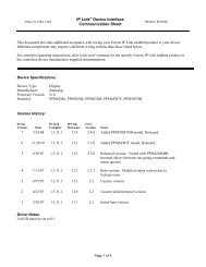
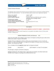
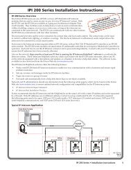
<strong>RGB</strong>-<strong>DVI</strong> <strong>300</strong> <strong>and</strong> <strong>RGB</strong>-<strong>HDMI</strong> <strong>300</strong> Description<br />
The <strong>RGB</strong>-<strong>DVI</strong> <strong>300</strong> <strong>and</strong> <strong>RGB</strong>-<strong>HDMI</strong> <strong>300</strong> are analog to digital<br />
video converters with built-in scaling.<br />
The units accept a single <strong>RGB</strong> or HDTV component (R-Y, Y, B-Y)<br />
input video signal at any st<strong>and</strong>ard <strong>RGB</strong> or HDTV component<br />
resolution, through a female 15-pin HD connector.<br />
A single video output at any of large range of resolutions<br />
<strong>and</strong>/or refresh rates is provided through a <strong>DVI</strong>-I (<strong>RGB</strong>-<strong>DVI</strong> <strong>300</strong>)<br />
or <strong>HDMI</strong> (<strong>RGB</strong>-<strong>HDMI</strong> <strong>300</strong>) connector.<br />
Input <strong>and</strong> output settings, picture controls, <strong>and</strong> advanced<br />
settings can be adjusted through the front panel menu with<br />
on-screen display, or RS-232, using <strong>Extron</strong>'s Simple Instruction<br />
Set (SIS ) comm<strong>and</strong>s.<br />
<strong>Extron</strong><br />
MVX 128 VGA A<br />
VGA & Audio<br />
Matrix Switcher<br />
1<br />
2<br />
LISTED<br />
1T23<br />
I.T.E.<br />
C U S<br />
3<br />
4<br />
5<br />
6<br />
INPUTS<br />
7<br />
8<br />
INPUTS<br />
1 2 3 4 5 6 7 8 9 10 11 12<br />
PC<br />
9<br />
10<br />
11<br />
12<br />
1<br />
2<br />
<strong>RGB</strong>-<strong>DVI</strong> <strong>300</strong> <strong>and</strong> <strong>RGB</strong>-<strong>HDMI</strong> <strong>300</strong> • Introduction<br />
3<br />
4<br />
OUTPUTS<br />
OUTPUTS<br />
1 2 3 4 5 6 7 8<br />
5<br />
6<br />
7<br />
8<br />
7<br />
8<br />
RESET<br />
LAN<br />
REMOTE<br />
RS232/RS422<br />
POWER<br />
12V<br />
0.5A MAX<br />
<strong>RGB</strong> INPUT<br />
<strong>RGB</strong> - <strong>HDMI</strong> <strong>300</strong><br />
<strong>Extron</strong><br />
<strong>RGB</strong>-<strong>HDMI</strong> <strong>300</strong><br />
<strong>RGB</strong> to <strong>HDMI</strong> Scaler<br />
RS-232<br />
<strong>HDMI</strong> OUTPUT<br />
Tx Rx<br />
Flat Panel Display
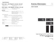
<strong>RGB</strong>-<strong>DVI</strong> <strong>300</strong> <strong>and</strong> <strong>RGB</strong>-<strong>HDMI</strong> <strong>300</strong> Features<br />
Accept all st<strong>and</strong>ard <strong>RGB</strong> <strong>and</strong> HDTV YUV inputs — through a female<br />
15-pin HD connector.<br />
Multiple output resolutions — These units can output an extensive<br />
range of unique <strong>DVI</strong> (or <strong>HDMI</strong>) combinations of resolution/<br />
refresh rate. Resolutions range from 640x480 to 1920x1200,<br />
including 1080p, with refresh rates ranging from 23.98 to 75 Hz.<br />
Auto Image — This feature automatically optimizes the image to the<br />
scaled output rate, eliminating complex setup.<br />
Simple Instruction Set comm<strong>and</strong>s — RS-232 ports on the front <strong>and</strong><br />
back panels allow easy configuration by a host device, using<br />
<strong>Extron</strong> SIS comm<strong>and</strong>s.<br />
Complete picture control adjustment — Input <strong>and</strong> output video<br />
signals can be fully adjusted through the front panel menu or<br />
through serial SIS comm<strong>and</strong>s.<br />
Front panel menu selection — The front panel buttons can be used to<br />
navigate <strong>and</strong> select menu options with the on-screen display.<br />
Preset values — 16 Input Presets <strong>and</strong> 3 User Presets make it easy to<br />
save <strong>and</strong> recall commonly used input sources.<br />
Front panel security lockout — This feature locks all front panel<br />
controls to prevent accidental or unauthorized reconfiguration.<br />
Easy mounting — The 1" H x 8.75" W x 6" D (2.6 cm H x<br />
22.2 cm W x 15.2 cm D) size of the units allows a wide range of<br />
mounting options.<br />
<strong>RGB</strong>-<strong>DVI</strong> <strong>300</strong> <strong>and</strong> <strong>RGB</strong>-<strong>HDMI</strong> <strong>300</strong> • Introduction<br />
1-3
Introduction, cont’d<br />
1-4<br />
<strong>RGB</strong>-<strong>DVI</strong> <strong>300</strong> <strong>and</strong> <strong>RGB</strong>-<strong>HDMI</strong> <strong>300</strong> • Introduction
<strong>RGB</strong>-<strong>DVI</strong> <strong>300</strong> <strong>and</strong> <strong>RGB</strong>-<strong>HDMI</strong> <strong>300</strong><br />
2<br />
Chapter Two<br />
Installation<br />
Mounting the Scalers<br />
Front Panel Layout<br />
Rear Panel Layout
Installation<br />
2-2<br />
Mounting the Scalers<br />
The 1" height <strong>and</strong> half rack width of the <strong>RGB</strong>-<strong>DVI</strong> <strong>300</strong> <strong>and</strong><br />
<strong>RGB</strong>-<strong>HDMI</strong> <strong>300</strong> units allow them to be mounted on a tabletop,<br />
on racks, under furniture, or through furniture.<br />
Tabletop placement<br />
Attach the four provided rubber feet to the bottom of the unit<br />
<strong>and</strong> place it in any convenient location.<br />
Rack Mounting<br />
UL guidelines for rack mounting<br />
The following Underwriters Laboratories (UL) guidelines are<br />
relevant to the safe installation of these products in a rack:<br />
1. Elevated operating ambient temperature — If the unit<br />
is installed in a closed or multi-unit rack assembly, the<br />
operating ambient temperature of the rack environment<br />
may be greater than room ambient temperature. Therefore,<br />
install the equipment in an environment compatible with<br />
the maximum ambient temperature (Tma: +122 °F, +50 °C)<br />
specified by <strong>Extron</strong>.<br />
2. Reduced air flow — Install the equipment in the rack<br />
so that the equipment gets adequate air flow for safe<br />
operation.<br />
3. Mechanical loading — Mount the equipment in the rack<br />
so that uneven mechanical loading does not create a<br />
hazardous condition.<br />
4. Circuit overloading — Connect the equipment to<br />
the supply circuit <strong>and</strong> consider the effect that circuit<br />
overloading might have on overcurrent protection<br />
<strong>and</strong> supply wiring. Appropriate consideration of the<br />
equipment nameplate ratings should be used when<br />
addressing this concern.<br />
5. Reliable earthing (grounding) — Maintain reliable<br />
grounding of rack-mounted equipment. Pay particular<br />
attention to supply connections other than direct<br />
connections to the branch circuit (such as the use of power<br />
strips).<br />
<strong>RGB</strong>-<strong>DVI</strong> <strong>300</strong> <strong>and</strong> <strong>RGB</strong>-<strong>HDMI</strong> <strong>300</strong> • Installation
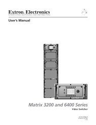
Rack mounting procedure<br />
The unit can be mounted on any of these rack systems:<br />
•<br />
•<br />
•<br />
•<br />
RSU 129: 9.5" deep, 1U rack shelf kit (part # 60-190-01)<br />
RSB 129: 9.5" deep, 1U basic rack shelf (part # 60-604-01)<br />
RSU 126: 6" deep, 1U rack shelf kit (part # 60-190-10)<br />
RSB 126: 6" deep, 1U basic rack shelf (part # 60-604-10)<br />
1. Remove rubber feet if these have been installed on the<br />
bottom of the unit.<br />
2. Align the holes in the base of the unit with holes in the<br />
shelf. Secure the unit to the shelf with two 4-40 x 3/16"<br />
screws in diagonally opposite corners (see the figure<br />
below).<br />
3. Install false faceplate(s) or other unit(s) on the rack shelf.<br />
4. Attach the shelf to the rack with the four provided<br />
10-32 x 3/4" bolts<br />
Front false<br />
faceplate<br />
uses 2<br />
screws.<br />
Rack mounting<br />
6" Deep Rack Shelf<br />
Use 2 mounting holes on<br />
opposite corners.<br />
1/2 Rack Width Front False<br />
Faceplate<br />
<strong>RGB</strong>-<strong>DVI</strong> <strong>300</strong> <strong>and</strong> <strong>RGB</strong>-<strong>HDMI</strong> <strong>300</strong> • Installation<br />
(2) 4-40 x 3/16"<br />
Screws<br />
2-3
Installation, cont’d<br />
2-4<br />
Under-desk/wall mounting<br />
Mount the unit under a desk or podium or to a wall, using<br />
the optional <strong>Extron</strong> MBU 125 under-desk mounting kit<br />
(part # 70-077-01) as follows:<br />
1. Remove rubber feet if these have been attached.<br />
2. Secure the mounting brackets to the scaler, using the four<br />
4-40 x 3/16" screws provided.<br />
N Because of the position of the mounting holes, the<br />
units must be mounted upside-down under the desk or<br />
podium, or with the bottom surface facing the wall.<br />
Under-desk mounting<br />
3. Hold the unit, with the brackets attached, against the wall<br />
or under the table or other furniture. Mark the location of<br />
the bracket s' screw holes on the mounting surface.<br />
4. Drill four pilot holes, each 3/32" (2 mm) in diameter by<br />
1/4" (6.3 mm) deep in the mounting surface at the marked<br />
screw locations.<br />
5. Insert #8 wood screws into the four pilot holes. Tighten<br />
each screw into the mounting surface until just less than<br />
1/4" (6.3 mm) of the screw head protrudes.<br />
6. Guide the mounting screws through the slots in the<br />
brackets <strong>and</strong> place the unit tight against the surface.<br />
7. Slide the unit slightly in or out so that the brackets are<br />
resting on the screws <strong>and</strong> support the weight of the unit;<br />
tighten all four screws to secure the unit in place (see the<br />
figure above).<br />
<strong>RGB</strong>-<strong>DVI</strong> <strong>300</strong> <strong>and</strong> <strong>RGB</strong>-<strong>HDMI</strong> <strong>300</strong> • Installation
Through-desk mounting<br />
Mount the unit through a desk or podium using the optional<br />
<strong>Extron</strong> MBD 129 through desk mounting kit (part # 70-077-02) as<br />
follows:<br />
1. Remove rubber feet if these have been attached.<br />
2. Attach the brackets to the scaler, using the four 4-40 screws<br />
provided; leave the screws slightly loose.<br />
Through-desk mounting<br />
3. Hold the unit in position, under the mounting surface.<br />
Mark the location of the four screw holes <strong>and</strong> the<br />
mounting hole to be cut in the table.<br />
4. Remove the table material. Test the fit by inserting the<br />
front of the device through the hole. If necessary, use a<br />
rasp or coarse file to enlarge the hole.<br />
5. Drill four pilot holes, each 3/32" (2 mm) in diameter by<br />
1/4" deep (6.3 mm) deep.<br />
6. Attach the brackets to the mounting surface, using the four<br />
#8 wood screws provided with the kit.<br />
7. Slide the device in or out until the front panel is flush with<br />
the table surface. Tighten the screws installed in step 2.<br />
8. If these screws are inaccessible to a screwdriver, mark the<br />
location of the unit relative to the brackets, remove the unit<br />
<strong>and</strong> brackets, tighten the screws, <strong>and</strong> replace the unit.<br />
<strong>RGB</strong>-<strong>DVI</strong> <strong>300</strong> <strong>and</strong> <strong>RGB</strong>-<strong>HDMI</strong> <strong>300</strong> • Installation<br />
2-5
Installation, cont’d<br />
2-6<br />
Front Panel Layout<br />
The illustration below shows the front panel features <strong>and</strong><br />
controls of the <strong>RGB</strong>-<strong>HDMI</strong> <strong>300</strong> (upper image) <strong>and</strong> <strong>RGB</strong>-<strong>DVI</strong> <strong>300</strong><br />
(lower image):<br />
a<br />
b<br />
c<br />
d<br />
CONFIG<br />
CONFIG<br />
MENU ENTER<br />
1 2 3 4<br />
Front panel layout<br />
MENU ENTER<br />
<strong>RGB</strong>-<strong>DVI</strong> <strong>300</strong> <strong>and</strong> <strong>RGB</strong>-<strong>HDMI</strong> <strong>300</strong> • Installation<br />
ADJUST<br />
ADJUST<br />
<strong>RGB</strong> - <strong>HDMI</strong> <strong>300</strong><br />
<strong>RGB</strong> - <strong>DVI</strong> <strong>300</strong><br />
LED indicator — A solid green light indicates the unit is<br />
receiving power <strong>and</strong> has an active video input. A solid amber<br />
light indicates the unit is receiving power but no video input.<br />
Config port — Both models can be configured using the <strong>Extron</strong><br />
Simple Instruction Set (SIS ) comm<strong>and</strong>s or through the Signal<br />
Processing Products Control Program (SPPCP). Either type of<br />
control is provided through this 2.5 mm Tip Ring Sleeve (TRS)<br />
serial configuration port or the RS-232 captive screw connector<br />
on the rear panel ( 8 ). See chapter 4 for instructions about SIS<br />
comm<strong>and</strong>s <strong>and</strong> the control software.<br />
Menu <strong>and</strong> Enter buttons — These buttons are used to navigate<br />
the menu when configuring the input <strong>and</strong> output video signals<br />
(see page 3-8) <strong>and</strong> to enable <strong>and</strong> disable the Front Panel Security<br />
Lockout (Executive mode; see page 3-8).<br />
N To see menu selections, a display device must be attached<br />
to the output of the video converter.<br />
Rotary encoders — The horizontal <strong>and</strong> vertical rotary encoders<br />
highlight menu items <strong>and</strong> adjust the value of items that have<br />
been selected from the menu.
Rear Panel Layout<br />
The illustration below shows the rear panel features of the<br />
<strong>RGB</strong>-<strong>HDMI</strong> <strong>300</strong> (upper image) <strong>and</strong> <strong>RGB</strong>-<strong>DVI</strong> <strong>300</strong> (lower image):<br />
POWER<br />
12V<br />
1.0A MAX<br />
<strong>RGB</strong>/ R-Y, Y, B-Y INPUT<br />
<strong>RGB</strong> - <strong>HDMI</strong> <strong>300</strong><br />
<strong>HDMI</strong> OUTPUT<br />
5 6<br />
7 8<br />
POWER<br />
12V<br />
1.0A MAX<br />
e<br />
f<br />
g<br />
h<br />
<strong>RGB</strong>/ R-Y, Y, B-Y INPUT<br />
Rear panel layout<br />
<strong>RGB</strong> - <strong>DVI</strong> <strong>300</strong><br />
<strong>DVI</strong>-D OUTPUT<br />
Power input — Connect the 12 VDC external power supply<br />
(provided) to this 3.5 mm, 2-pole captive screw connector.<br />
<strong>RGB</strong> input — Connect an analog <strong>RGB</strong> or HDTV YUV video<br />
input signal to this female 15-pin HD connector.<br />
Digital signal output — Both models output digital signals.<br />
The <strong>RGB</strong>-<strong>DVI</strong> <strong>300</strong> outputs a <strong>DVI</strong>-D signal through a female<br />
<strong>DVI</strong>-I connector; the <strong>RGB</strong>-<strong>HDMI</strong> <strong>300</strong> outputs an <strong>HDMI</strong> signal<br />
through a female <strong>HDMI</strong> connector.<br />
RS-232 input — Both models can be configured by using SIS<br />
comm<strong>and</strong>s or through the SPPCP. Either means of control is<br />
provided through this 3.5 mm, 3-pole captive screw RS-232<br />
serial port connector or the TRS config port on the front panel<br />
( 2 ). See chapter 4 for instructions about SIS comm<strong>and</strong>s <strong>and</strong><br />
control software.<br />
<strong>RGB</strong>-<strong>DVI</strong> <strong>300</strong> <strong>and</strong> <strong>RGB</strong>-<strong>HDMI</strong> <strong>300</strong> • Operation<br />
RS-232<br />
Tx Rx<br />
RS-232<br />
Tx Rx<br />
2-7
Installation, cont’d<br />
2-8<br />
<strong>RGB</strong>-<strong>DVI</strong> <strong>300</strong> <strong>and</strong> <strong>RGB</strong>-<strong>HDMI</strong> <strong>300</strong> • Installation
<strong>RGB</strong>-<strong>DVI</strong> <strong>300</strong> <strong>and</strong> <strong>RGB</strong>-<strong>HDMI</strong> <strong>300</strong><br />
3<br />
Chapter Three<br />
Operation<br />
Input <strong>and</strong> Output Configuration<br />
Front Panel Connections <strong>and</strong> Controls<br />
Rear Panel Connections
Operation<br />
3-2<br />
Input <strong>and</strong> Output Configuration<br />
The on-screen display menu <strong>and</strong> the serial ports can be used<br />
to configure the unit's input <strong>and</strong> output signals. "Front panel<br />
menu controls" later in this chapter has instructions on using the<br />
front panel menu. Chapter 4 has instructions for SIS comm<strong>and</strong>s<br />
to the unit.<br />
Vertical<br />
Start<br />
Total<br />
Lines Active<br />
Lines<br />
The figure below shows how some of the settings of a video<br />
signal are defined. The active area is the image seen on the<br />
screen. The blanking area is the part of each frame containing<br />
additional information that allows the display device to position<br />
the image.<br />
Horizontal<br />
Start<br />
Blanking Area<br />
Active Area<br />
Active Pixels<br />
Total Pixels<br />
Input signal<br />
Signal type — <strong>RGB</strong> or HDTV component (Y, R-Y, B-Y)<br />
Total pixels — The total number of pixels in a line, including<br />
blanking on both sides of the input active area (active,<br />
horizontal sync width, back porch, <strong>and</strong> front porch). The values<br />
can be adjusted from the default value ± 512.<br />
N The total number of lines per frame, including the<br />
blanking above <strong>and</strong> below the active area is determined<br />
by the input signal <strong>and</strong> is not user adjustable.<br />
N Default values for the detected input rate for total pixels,<br />
active pixels, <strong>and</strong> active lines are shown with an asterisk<br />
(*) in the on-screen display.<br />
<strong>RGB</strong>-<strong>DVI</strong> <strong>300</strong> <strong>and</strong> <strong>RGB</strong>-<strong>HDMI</strong> <strong>300</strong> • Operation
Start — The horizontal start defines the number of pixels in<br />
the blanking area to the left of the active area; the vertical start<br />
defines the number of pixels above the active area.<br />
N The vertical <strong>and</strong> horizontal starts <strong>and</strong> the active area<br />
must be set to frame the active area of the input signal.<br />
If these values are set incorrectly, the scaler may crop<br />
trailing edges (right or bottom) or partially mask the<br />
leading edges (left or top).<br />
Active pixels — The number of pixels per line that are inside<br />
the active area. The baseline for the active pixels adjustment<br />
depends on the horizontal <strong>and</strong> vertical resolutions of the input<br />
signal. The values can be adjusted from the default value ± 512.<br />
N The horizontal active pixels <strong>and</strong> total pixels adjustments<br />
are interactive. Setting one of these variables may<br />
require the other to be adjusted.<br />
Active lines — The number of horizontal lines inside the active<br />
area. The baseline for the active lines adjustment depends on<br />
the input <strong>and</strong> output resolutions. The values can be adjusted<br />
from the default value ± 256.<br />
Phase — The timing of the digital scaler’s sampling. Sampling<br />
at the optimum pixel phase results in a bright, stable output.<br />
N Total pixels <strong>and</strong> active pixels must be correctly set before<br />
adjusting phase.<br />
Output Signal<br />
Auto Image — Automatically sizes <strong>and</strong> centers the input signal<br />
to fill the screen of the output device. Auto Image can be used<br />
to configure each input rate separately, or it can be enabled, in<br />
the advanced menu, to automatically size <strong>and</strong> center each new<br />
input rate.<br />
Picture position — Sets the horizontal <strong>and</strong> vertical centers for<br />
the output image.<br />
Picture size — Sets the size of the output image so that it can fill<br />
the entire display device.<br />
Detail filter — Uses variable filters to increase or decrease the<br />
detail <strong>and</strong> definition of the displayed image. The value can be<br />
adjusted on a scale from 0 to 127. The default setting is 64.<br />
Brightness — Brightness adjusts the black level of the image on<br />
the screen, on a scale from 0 to 127. The default setting is 64.<br />
Contrast — Contrast adjusts the difference between the input's<br />
darkest <strong>and</strong> brightest settings, on a scale from 0 to 127 (the<br />
default is 64).<br />
<strong>RGB</strong>-<strong>DVI</strong> <strong>300</strong> <strong>and</strong> <strong>RGB</strong>-<strong>HDMI</strong> <strong>300</strong> • Operation<br />
3-3
Operation, cont’d<br />
Table of Output Resolutions <strong>and</strong> Refresh Rates<br />
3-4<br />
Resolution Refresh Rate (Hz)<br />
23.98 24 25 29.97 30 50 59.94 60 75<br />
640 x 480 X X X<br />
800 x 600 X X X<br />
852 x 480 X X X<br />
1024 x 768 X X X<br />
1024 x 852 X X X<br />
1024 x 1024 X X X<br />
1280 x 768 X X X<br />
1280 x 800 X X X<br />
1280 x 1024 X X X<br />
1360 x 765 X X X<br />
1360 x 768 X X X<br />
<strong>RGB</strong>-<strong>DVI</strong> <strong>300</strong> <strong>and</strong> <strong>RGB</strong>-<strong>HDMI</strong> <strong>300</strong> • Operation<br />
1365 x 768 X X X<br />
1366 x 768 X X X<br />
1365 x 1024 X X<br />
1440 x 900 X X X<br />
1400 x 1050 X X
Resolution Refresh Rate (Hz)<br />
23.98 24 25 29.97 30 50 59.94 60 75<br />
1680 x 1050 X X<br />
1600 x 1200 X X<br />
1920 x 1200 X X<br />
480p X X<br />
576p X<br />
720p X X X X X X<br />
1080i X X X<br />
1080p X X X X X X X X<br />
2048 x 1080 X X X X X X X X<br />
AUTO Output resolution based on display EDID<br />
LOCK Output rate will match input resolution <strong>and</strong> refresh rate<br />
<strong>RGB</strong>-<strong>DVI</strong> <strong>300</strong> <strong>and</strong> <strong>RGB</strong>-<strong>HDMI</strong> <strong>300</strong> • Operation<br />
3-5
Operation, cont’d<br />
3-6<br />
Zoom — Zoom enlarges a portion of the scaled image.<br />
N Zoom values match picture size values.<br />
Output Resolution <strong>and</strong> refresh rate — Every display device has<br />
an optimal (native) resolution <strong>and</strong> refresh rate. It is essential<br />
that the output resolution <strong>and</strong> refresh rate match the display<br />
device's capabilities. The table on the two previous pages<br />
shows the full range of resolutions <strong>and</strong> refresh rates available<br />
for output signals with these scalers. There are two additional<br />
settings:<br />
• When Auto is selected, the video converter receives EDID<br />
information from the display device <strong>and</strong> adjusts the output<br />
signal to match the requirements of the display<br />
• When Lock is selected, the video converter matches the<br />
resolution <strong>and</strong> refresh rate of the output signal with those of<br />
the input signal.<br />
Other<br />
User presets — When contrast, brightness, detail, horizontal<br />
<strong>and</strong> vertical centering, <strong>and</strong> horizontal <strong>and</strong> vertical size have<br />
been adjusted, the values can be saved as presets. This allows<br />
the values for the three most commonly used picture control<br />
settings to be instantly recalled, which is useful for h<strong>and</strong>ling<br />
inputs with different aspect ratios.<br />
Test pattern — Test patterns help in the configuration of the<br />
output signal. The available patterns include Color Bars,<br />
grayscale, cross-hatch, alternating pixels, crop, 1.33 aspect ratio,<br />
1.78 aspect ratio, 1.85 aspect ratio, 2.35 aspect ratio, <strong>and</strong> off (no<br />
test pattern).<br />
Freeze — When freeze is enabled, the video output is a still<br />
image of the last active frame. The output will remain frozen<br />
even if the input signal is removed.<br />
Blank — When blank is enabled, no video signal is sent to the<br />
output device, although the on-screen display is still available.<br />
Reset — There are two types of reset. Firmware reset returns all<br />
options, including the firmware to the factory defaults. Factory<br />
reset returns all image options to the factory defaults but keeps<br />
the current version of the firmware. For more information, see<br />
page 3-17.<br />
<strong>RGB</strong>-<strong>DVI</strong> <strong>300</strong> <strong>and</strong> <strong>RGB</strong>-<strong>HDMI</strong> <strong>300</strong> • Operation
Front Panel Connections <strong>and</strong> Controls<br />
The front panels of both the <strong>RGB</strong>-<strong>DVI</strong> <strong>300</strong> <strong>and</strong> the<br />
<strong>RGB</strong>-<strong>HDMI</strong> <strong>300</strong> have a green/amber LED indicator, a config<br />
port, menu <strong>and</strong> enter buttons, <strong>and</strong> two rotary encoders (see<br />
page 2-6).<br />
LED indicator<br />
A green light indicates the unit is receiving power <strong>and</strong> has an<br />
active video input. An amber light indicates the unit is receiving<br />
power but no video input.<br />
Config port<br />
Both the video scaler/converters accept SIS comm<strong>and</strong>s from<br />
a host device such as a computer running the HyperTerminal<br />
utility or other control system.<br />
To connect the host device to the config port on the front<br />
panel, use the optional <strong>Extron</strong> 9-pin D female to 2.5 mm TRS<br />
Configuration Cable (PN 70-335-01). The same port can also be<br />
used to provide control by the SPPCP. For more information<br />
about SIS <strong>and</strong> the control software, see chapter 4.<br />
1 5<br />
6 9<br />
Male DB9 Connector<br />
Pin Configuration<br />
2.5 mm TRS Connector<br />
Male TRS RS-232<br />
Pin Function<br />
2 Tip Transmit (Tx)<br />
3 Ring Receive (Rx)<br />
5 Sleeve Ground ( )<br />
Tip<br />
Ring<br />
Sleeve (Gnd)<br />
Control comm<strong>and</strong>s can also be sent through the 3-pin captive<br />
screw connector on the rear panel (see page 3-20).<br />
N Only one serial port can be used at a time. If the front<br />
port is in use, the rear captive screw connector must be<br />
disconnected from the computer or other control device.<br />
Likewise, if the captive screw port is in use, the Config<br />
port on the front panel must be disconnected from the<br />
computer or other control device.<br />
<strong>RGB</strong>-<strong>DVI</strong> <strong>300</strong> <strong>and</strong> <strong>RGB</strong>-<strong>HDMI</strong> <strong>300</strong> • Operation<br />
3-7
Operation, cont’d<br />
3-8<br />
Front panel menu controls<br />
The menu <strong>and</strong> enter buttons <strong>and</strong> rotary encoders are used to<br />
configure <strong>and</strong> optimize the unit's input <strong>and</strong> output signals.<br />
N The menus for the <strong>RGB</strong>-<strong>DVI</strong> <strong>300</strong> <strong>and</strong> <strong>RGB</strong>-<strong>HDMI</strong> <strong>300</strong><br />
are On-Screen Dipslay (OSD). To see menu selections, a<br />
display device must be attached to the output of the video<br />
scaler/converter.<br />
Front panel security lockout (executive mode)<br />
When the front panel security lockout, also known as executive<br />
mode, is enabled, all front panel controls are locked. RS-232<br />
control remains available.<br />
Front panel security lockout is enabled by pressing <strong>and</strong> holding<br />
the menu <strong>and</strong> enter buttons simultaneously for two seconds.<br />
It can also be enabled using an SIS comm<strong>and</strong> (see page 4-14).<br />
When front panel security lockout has been enabled, the<br />
following message will appear on-screen for approximately two<br />
seconds:<br />
This message also displays if the user attempts to use any of the<br />
front panel controls while the executive mode is enabled.<br />
Front panel security lockout is disabled by pressing <strong>and</strong> holding<br />
the menu <strong>and</strong> enter buttons simultaneously for two seconds. It<br />
can also be disabled by sending the appropriate SIS comm<strong>and</strong><br />
(see page 4-15). When front panel security lockout has been<br />
disabled, the following message will appear on-screen for<br />
approximately two seconds:<br />
When front panel security lockout is disabled, the unit can be<br />
fully configured from the front panel without restrictions.<br />
Main menu<br />
The menu <strong>and</strong> enter buttons <strong>and</strong> the two rotary encoders are<br />
used to enter <strong>and</strong> navigate the menu, which is displayed on the<br />
output screen.<br />
MENU ENTER<br />
ADJUST<br />
<strong>RGB</strong>-<strong>DVI</strong> <strong>300</strong> <strong>and</strong> <strong>RGB</strong>-<strong>HDMI</strong> <strong>300</strong> • Operation
Press the Menu button to open the menu. A header that<br />
identifies the model <strong>and</strong> the top-level menu appears on the<br />
output display.<br />
N In all following figures the <strong>RGB</strong>-<strong>DVI</strong> <strong>300</strong> has been used<br />
in the illustrations. Apart from the heading, the<br />
<strong>RGB</strong>-<strong>HDMI</strong> <strong>300</strong> menu is identical in all respects.<br />
The six options of the top-level menu are Auto-Image,<br />
Picture Controls, User Presets, Input Configuration, Output<br />
Configuration, <strong>and</strong> Advanced Configuration.<br />
The option that is currently highlighted appears as white text<br />
in a light blue box, with a white border. The other options <strong>and</strong><br />
the header are shown as white text in a dark blue box. Turn the<br />
{ rotary encoder to move between menu items <strong>and</strong> highlight the<br />
desired option.<br />
Press the Enter to select the highlighted button <strong>and</strong> move deeper<br />
into the menu. Press the Menu button to return to a higher level<br />
of the menu system. When a sub-menu item is highlighted, it<br />
appears as a light blue box with white text <strong>and</strong> a white border.<br />
To select that item, press the Enter button again. The selected<br />
item will appear as a gray box with white text <strong>and</strong> a white<br />
border.<br />
<strong>RGB</strong>-<strong>DVI</strong> <strong>300</strong> <strong>and</strong> <strong>RGB</strong>-<strong>HDMI</strong> <strong>300</strong> • Operation<br />
3-9
Operation, cont’d<br />
3-10<br />
Auto Image<br />
The Auto Image function automatically sizes <strong>and</strong> centers the<br />
input to fill the screen. It is activated by pressing the enter<br />
button after Auto Image has been selected.<br />
N This feature initiates a one-time auto image on the<br />
current input. Auto image can also be set globally, using<br />
the Advanced Configuration menu, to size <strong>and</strong> center<br />
each new input rate, automatically.<br />
<strong>RGB</strong>-<strong>DVI</strong> <strong>300</strong> <strong>and</strong> <strong>RGB</strong>-<strong>HDMI</strong> <strong>300</strong> • Operation
Picture controls<br />
The picture controls sub-menu sets horizontal <strong>and</strong> vertical<br />
centering, sizing, brightness <strong>and</strong> contrast, <strong>and</strong> detail (sharpness)<br />
<strong>and</strong> controls the zoom feature. Use the { knob to select from the<br />
sub-menu, <strong>and</strong> press the enter button.<br />
The values for position (H), size (H), <strong>and</strong> brightness are<br />
adjusted using the [ knob. The values for position (V), size<br />
(V), <strong>and</strong> contrast are adjusted using the { knob. The values for<br />
detail <strong>and</strong> zoom can be adjusted using either knob.<br />
Zoom locks the aspect ratio as the image is resized. Zoom is<br />
pixel based (not percentage based), so the current Zoom values<br />
for H <strong>and</strong> V will match the current Size values for H <strong>and</strong> V.<br />
Once the input has been zoomed, the H <strong>and</strong> V positions can be<br />
adjusted to obtain a panning effect.<br />
Option Minimum Maximum<br />
Position Depends on output resolution<br />
Size Depends on output resolution<br />
Brightness 0 127<br />
Contrast 0 127<br />
Zoom Depends on output resolution<br />
User presets<br />
User presets are a user defined set of picture control settings for<br />
up to three commonly used aspect ratio settings. When picture<br />
controls <strong>and</strong> input configuration have been set, as described<br />
elsewhere in this section, the current values for contrast,<br />
<strong>RGB</strong>-<strong>DVI</strong> <strong>300</strong> <strong>and</strong> <strong>RGB</strong>-<strong>HDMI</strong> <strong>300</strong> • Operation<br />
3-11
Operation, cont’d<br />
3-12<br />
brightness, detail, horizontal <strong>and</strong> vertical centering, <strong>and</strong><br />
horizontal <strong>and</strong> vertical size can be saved. User presets can be<br />
saved on one input rate <strong>and</strong> recalled for a different input rate.<br />
To save user presets, navigate to the User Presets > Save submenu.<br />
Use the { knob to select user preset 1, 2, or 3 <strong>and</strong> press<br />
Enter to save, <strong>and</strong> press Menu to exit.<br />
When a preset has been saved, it can be recalled or cleared using<br />
the Recall or Clear options. Select a memory preset (1, 2, or 3)<br />
to be recalled or cleared <strong>and</strong> press Enter.<br />
N The brackets around the current selection are only<br />
visible when that function (recall, save, or clear) has been<br />
activated. Attempts to recall a memory preset that has<br />
not yet been saved, <strong>and</strong> "Invalid Preset" message will<br />
appear on the on-screen display.<br />
User Presets Input Presets<br />
H position Input type H start H position<br />
V position Total Pixel V start V position<br />
Contrast H size Contrast H active H size<br />
Brightness V size Brightness V active V size<br />
Detail Zoom Detail Phase Zoom<br />
An additional sixteen presets (input presets) are available<br />
through SIS comm<strong>and</strong>s only. Input presets save picture control<br />
settings (the same values saved by user presets) <strong>and</strong> input<br />
configuration values (input type, total pixels, horizontal <strong>and</strong><br />
vertical starts, horizontal <strong>and</strong> vertical active areas <strong>and</strong> phase).<br />
The exact settings of a source are saved <strong>and</strong> can be recalled each<br />
<strong>RGB</strong>-<strong>DVI</strong> <strong>300</strong> <strong>and</strong> <strong>RGB</strong>-<strong>HDMI</strong> <strong>300</strong> • Operation
time that source is used. Input presets are only valid for the<br />
source/resolution that was active when the preset was saved.<br />
Input configuration<br />
The input configuration submenu is used to adjust input type,<br />
total pixels, phase, horizontal <strong>and</strong> vertical video start, <strong>and</strong><br />
horizontal <strong>and</strong> vertical active areas.<br />
N On the on-screen menu display, default values for the<br />
current input rates, total pixels, H active, <strong>and</strong> V active<br />
are accompanied by an asterisk (*).<br />
With the start or active options, use the [ knob to adjust the<br />
horizontal values <strong>and</strong> the { knob to adjust the vertical values.<br />
Total pix <strong>and</strong> phase are adjusted by the [ <strong>and</strong> { knobs,<br />
respectively.<br />
Option Minimum Maximum<br />
Input <strong>RGB</strong> (default) or YUV<br />
Total Pix default value (depends on input resolution) ± 512<br />
Phase 0 31<br />
Horizontal start 0<br />
255<br />
Vertical start<br />
0<br />
255<br />
Active Pixels default value (depends on input resolution) ± 512<br />
Active Lines default value (depends on input resolution) ± 256<br />
<strong>RGB</strong>-<strong>DVI</strong> <strong>300</strong> <strong>and</strong> <strong>RGB</strong>-<strong>HDMI</strong> <strong>300</strong> • Operation<br />
3-13
Operation, cont’d<br />
3-14<br />
Output configuration<br />
The output configuration is used to select a scaler output rate<br />
from the various available resolution <strong>and</strong> refresh rates. Both<br />
the <strong>RGB</strong>-<strong>DVI</strong> <strong>300</strong> <strong>and</strong> the <strong>RGB</strong>-<strong>HDMI</strong> <strong>300</strong> have a large range of<br />
combinations of resolution <strong>and</strong> refresh rate (see table on pages<br />
3-4 <strong>and</strong> 3-5).<br />
Select output configuration from the main menu. Use the<br />
[ knob to select a resolution. Then use the { knob to select a<br />
refresh rate. Apply the settings by pressing the enter button, or<br />
they will be applied automatically after 5 seconds.<br />
In addition to the resolutions <strong>and</strong> refresh rates available in the<br />
menu, two other options are available:<br />
Auto — The unit receives EDID information from the display<br />
device <strong>and</strong> adjusts the output signal to match the requirements<br />
of the display.<br />
Lock — The unit matches the resolution <strong>and</strong> refresh rate of the<br />
output signal with those of the input signal.<br />
When color space is selected, the two available options are <strong>RGB</strong><br />
(default) <strong>and</strong> YUV. Use the up/down rotary encoder to select<br />
the desired value <strong>and</strong> then apply the setting by pressing the<br />
enter button.<br />
<strong>RGB</strong>-<strong>DVI</strong> <strong>300</strong> <strong>and</strong> <strong>RGB</strong>-<strong>HDMI</strong> <strong>300</strong> • Operation
Advanced configuration<br />
The advanced configuration menu configures global settings,<br />
including Test Patterns, Blank, Freeze, Global Auto Image,<br />
Auto Memory, <strong>and</strong> Factory Reset.<br />
The advanced configuration is activated by pressing the menu<br />
button to display the main menu, using either rotary encoder to<br />
select advanced configuration <strong>and</strong> pressing the enter button.<br />
Test pattern can be set to Color Bars, grayscale, crosshatch,<br />
alternating pixels, crop, four different aspect ratios, or off. These<br />
patterns are used to configure the output signal.<br />
<strong>RGB</strong>-<strong>DVI</strong> <strong>300</strong> <strong>and</strong> <strong>RGB</strong>-<strong>HDMI</strong> <strong>300</strong> • Operation<br />
3-15
Operation, cont’d<br />
3-16<br />
Color Bars<br />
Alternating<br />
Pixels Crop<br />
1.78 Aspect<br />
Split Grayscale 4x4 Crosshatch<br />
1.85 Aspect 2.35 Aspect<br />
<strong>RGB</strong>-<strong>DVI</strong> <strong>300</strong> <strong>and</strong> <strong>RGB</strong>-<strong>HDMI</strong> <strong>300</strong> • Operation<br />
1.33 Aspect<br />
N All aspect ratio patterns also include a 1 pixel wide crop<br />
pattern at the edge of the video output raster.<br />
When Blank is enabled, there is no video output (aside from the<br />
on-screen display).<br />
When Freeze is on, the video output is a still picture of the last<br />
active frame.<br />
The Auto Image <strong>and</strong> Auto Memory functions work<br />
interactively. Either function can be on or off, giving four<br />
possible combinations.<br />
Auto Image on <strong>and</strong> Auto Memory on — If the Auto Image<br />
function is on, the output signal is sized <strong>and</strong> centered to fill the<br />
screen. If the Auto Memory function is on, these parameters<br />
are saved. The next time the unit encounters the same signal,<br />
the parameters saved by the Auto Memory are applied<br />
automatically.<br />
When all 64 memories are filled, the oldest is overwritten by<br />
new ones.<br />
Auto Image off <strong>and</strong> Auto Memory on — If the Auto Image is<br />
off, the unit applies the values from the input lookup table. If<br />
no further adjustments are made, the Auto Memory does not<br />
save an entry, since all the parameters already match the input<br />
lookup table. However, if the user adjusts the input manually or<br />
carries out an Auto Image, the new parameters is automatically<br />
stored by the Auto Memory function.
Auto Image on <strong>and</strong> Auto Memory off — Each new signal is<br />
compared with the values in the input lookup table <strong>and</strong> an<br />
Auto Image carried out. However, the parameters are not saved<br />
<strong>and</strong> the next time this signal is encountered, it is, once again,<br />
compared with the lookup table <strong>and</strong> Auto Imaged.<br />
Auto Image off <strong>and</strong> Auto Memory off — Each new signal is<br />
set up with the default values. There is no Auto Image <strong>and</strong> the<br />
parameters are not saved by the Auto Memory.<br />
To reset all user settings, but keep the current version of the<br />
firmware, enter the menu, select advanced configuration, <strong>and</strong><br />
Factory Reset. Press <strong>and</strong> hold the enter button until the "Factory<br />
Reset" message is displayed on the screen. This is the same as<br />
the Zap SIS comm<strong>and</strong> (EZXXX}), as shown on page 4-16.<br />
To reset all options, including the original shipped firmware<br />
to the factory defaults, press <strong>and</strong> hold the enter button while<br />
applying power; the "Firmware Reset" message is displayed on<br />
the on-screen display.<br />
When the output display has an incompatible output rate, it<br />
is often difficult to get an image on the display. An additional<br />
reset mode allows the user to toggle between two almost<br />
universally applicable output rates of 1024 x 768 at 60 Hz (XGA)<br />
<strong>and</strong> 720p at 60 Hz.<br />
Applying power to the unit while holding the Menu button<br />
initially changes to output rate to 1024 x 768 at 60 Hz. On the<br />
next occasion power is applied to the unit while holding the<br />
Menu button, the output rate toggles to 720p at 60 Hz.<br />
These values were chosen because most PC monitors with<br />
a digital input will accept an XGA signal <strong>and</strong> most other<br />
consumer/professional displays will accept 720p.<br />
<strong>RGB</strong>-<strong>DVI</strong> <strong>300</strong> <strong>and</strong> <strong>RGB</strong>-<strong>HDMI</strong> <strong>300</strong> • Operation<br />
3-17
Operation, cont’d<br />
Rear Panel Connections<br />
The rear panels of both the <strong>RGB</strong>-<strong>DVI</strong> <strong>300</strong> <strong>and</strong> the<br />
<strong>RGB</strong>-<strong>HDMI</strong> <strong>300</strong> have a power input, <strong>RGB</strong>/HDTV YUV signal<br />
input, digital signal output, <strong>and</strong> RS-232 port.<br />
3-18<br />
Power Connections<br />
1. Connect the captive screw connector from the supplied<br />
12 VDC power supply into the power receptacle.<br />
POWER<br />
12V<br />
1.0A MAX<br />
Back Panel<br />
Power Receptacle<br />
DC Power Cord<br />
Captive Screw Connector<br />
Ground<br />
+12 VDC<br />
AC Power Cord<br />
<strong>RGB</strong>-<strong>DVI</strong> <strong>300</strong> <strong>and</strong> <strong>RGB</strong>-<strong>HDMI</strong> <strong>300</strong> • Operation<br />
External<br />
Power Supply<br />
(12 VDC, 2 A )<br />
2. Connect the AC power cord of the power supply unit to a<br />
110 or 220 VAC electrical source.
Input Connections<br />
The <strong>RGB</strong>-<strong>DVI</strong> <strong>300</strong> <strong>and</strong> <strong>RGB</strong>-<strong>HDMI</strong> <strong>300</strong> accept <strong>RGB</strong> (<strong>RGB</strong>HV,<br />
<strong>RGB</strong>S, RGsB, <strong>and</strong> RsGsBs) <strong>and</strong> HDTV component (YUV)<br />
signals. Connect the input signal to the 15 pin female HD<br />
connector on the back of the scaler.<br />
If necessary, use a BNC to VGA adapter cable, such as the <strong>Extron</strong><br />
SY BNCM series (PN 26-533-xx; see the figure below).<br />
Output Connections<br />
Use the Female <strong>DVI</strong>-I connector (<strong>RGB</strong>-<strong>DVI</strong> <strong>300</strong>) or the Female<br />
<strong>HDMI</strong> connector (<strong>RGB</strong>-<strong>HDMI</strong> <strong>300</strong>) to pass the output signal to<br />
the display device.<br />
<strong>DVI</strong>-D OUTPUT<br />
Rear panel <strong>DVI</strong> connector (<strong>RGB</strong>-<strong>DVI</strong> <strong>300</strong>)<br />
N Although the <strong>RGB</strong>-<strong>DVI</strong> <strong>300</strong> has a rear panel <strong>DVI</strong>-I<br />
connector, the output signal is <strong>DVI</strong>-D (digital only).<br />
<strong>HDMI</strong> OUTPUT<br />
<strong>RGB</strong>HV<br />
<strong>RGB</strong>S<br />
RGsB,<br />
RsGsBs,<br />
Component<br />
R Gs B H V<br />
RsGsBs R-Y Y B-Y<br />
Rear panel <strong>HDMI</strong> connector (<strong>RGB</strong>-<strong>HDMI</strong> <strong>300</strong>)<br />
G B H V<br />
<strong>RGB</strong>-<strong>DVI</strong> <strong>300</strong> <strong>and</strong> <strong>RGB</strong>-<strong>HDMI</strong> <strong>300</strong> • Operation<br />
R<br />
R G B S V<br />
3-19
Operation, cont’d<br />
3-20<br />
RS-232 Connection<br />
Both the video scaler/converters accept SIS comm<strong>and</strong>s from<br />
a host device such as a computer running the HyperTerminal<br />
utility or other control system.<br />
The same port can also be used to provide control by the SPPCP.<br />
For more information about SIS <strong>and</strong> the SPPCP, see chapter 4.<br />
RS-232<br />
T R<br />
x x<br />
3 Pin Captive Screw Connector<br />
<strong>RGB</strong>-<strong>DVI</strong> <strong>300</strong> <strong>and</strong> <strong>RGB</strong>-<strong>HDMI</strong> <strong>300</strong> • Operation<br />
Pin Function<br />
T x Transmit data<br />
Rx Receive data<br />
Signal ground<br />
N The wiring in the RS-232 cables must cross over so that<br />
the transmit port of the control device connects with the<br />
receive port of the video converter <strong>and</strong> vice versa.<br />
Control comm<strong>and</strong>s can also be sent through the TRS Config port<br />
on the front panel (see page 3-7).<br />
N Only one serial port can be used at a time. If the front<br />
port is in use, the rear captive screw connector must be<br />
disconnected from the computer or other control device.<br />
Likewise, if the captive screw port is in use, the config<br />
port on the front panel must be disconnected from the<br />
computer or other control device.
<strong>RGB</strong>-<strong>DVI</strong> <strong>300</strong> <strong>and</strong> <strong>RGB</strong>-<strong>HDMI</strong> <strong>300</strong><br />
4<br />
Chapter Four<br />
Controls<br />
Introduction to SIS <br />
Symbols used in this manual<br />
Comm<strong>and</strong>/response table for SIS comm<strong>and</strong>s<br />
Signal Processing Products Control Program
Serial Communications<br />
4-2<br />
Introduction to SIS <br />
Both the <strong>RGB</strong>-<strong>DVI</strong> <strong>300</strong> <strong>and</strong> the <strong>RGB</strong>-<strong>HDMI</strong> <strong>300</strong> accept SIS<br />
comm<strong>and</strong>s from a host device such as a computer running the<br />
HyperTerminal utility or other control system. The host device<br />
can be connected to the 3-pin captive screw connector on the<br />
rear panel or to the Config port on the front panel. To connect<br />
to the config port, use the optional <strong>Extron</strong> 9-pin D female to 2.5<br />
mm TRS Configuration cable (part # 70-335-01).<br />
The protocol is 9600 baud, 8 data bit, 1 stop bit, <strong>and</strong> no parity.<br />
N The wiring in the RS-232 cables crosses over so that<br />
the video scaler/converter Tx connects with the control<br />
device Rx <strong>and</strong> vice versa.<br />
N Only one serial port can be used at a time. If the front<br />
port is in use, the rear captive screw connector must be<br />
disconnected from the computer or other control device.<br />
Likewise, if the captive screw port is in use, the config<br />
port on the front panel must be disconnected from the<br />
computer or other control device.<br />
SIS comm<strong>and</strong>s consist of a string (one or more characters per<br />
comm<strong>and</strong> field). Unless otherwise stated, upper <strong>and</strong> lower<br />
case characters may be used interchangeably. Comm<strong>and</strong>s do<br />
not require any special characters to begin or end the comm<strong>and</strong><br />
string. Each response from the video converter ends with a<br />
carriage return <strong>and</strong> a line feed (CR/LF = ]), which signals the<br />
end of the response character string.<br />
When the <strong>RGB</strong>-<strong>DVI</strong> <strong>300</strong> or <strong>RGB</strong>-<strong>HDMI</strong> <strong>300</strong> is first switched on,<br />
depending on the model, it sends the message:<br />
(c) COPYRIGHT 2009, EXTRON ELECTRONICS,<br />
<strong>RGB</strong>-<strong>DVI</strong> <strong>300</strong>, V x.xx, 60-906-01] or<br />
(c) COPYRIGHT 2009, EXTRON ELECTRONICS,<br />
<strong>RGB</strong>-<strong>HDMI</strong> <strong>300</strong>, V x.xx, 60-907-01]<br />
where V x.xx is the firmware version number <strong>and</strong> 60-90x-01 is<br />
the part number.<br />
<strong>RGB</strong>-<strong>DVI</strong> <strong>300</strong> <strong>and</strong> <strong>RGB</strong>-<strong>HDMI</strong> <strong>300</strong> • Serial Communications
Symbols used in this manual<br />
When programming in the field, certain characters are most<br />
conveniently represented by their hexadecimal rather than<br />
their ASCII values. The table below shows the hexadecimal<br />
equivalent of each ASCII character:<br />
Space<br />
ASCII to HEX Conversion Table<br />
] — carriage return with line feed<br />
} — carriage return (no line feed)<br />
• — space character<br />
E — Escape key<br />
The X/ values defined in this section are the variables used in<br />
the fields of the comm<strong>and</strong> response table (see page 4-6).<br />
X! — Input video format: 1 = <strong>RGB</strong> (default) 2 = YUV<br />
X@ — Auto image, blanking, freeze or executive mode status:<br />
0 = disabled 1 = enabled<br />
X# — Horizontal start value: from 0 to 255 (the midpoint of 128<br />
is the default value in the input lookup tables)<br />
X$ — Vertical start value: from 0 to 255 (the midpoint of 128 is<br />
the default value in the input lookup tables)<br />
X% — Pixel phase value: from 1 to 31 (default = 16)<br />
X^ — Total pixels value for high resolution video is the default<br />
value ± 512 (the default value depends on the the input<br />
resolution)<br />
X& — Active pixels value for high resolution video is the<br />
default value ± 512 (the default value depends on the the<br />
input resolution)<br />
X* — Active lines value for high resolution video is the default<br />
value ± 256 (the default value depends on the the input<br />
resolution)<br />
X1) — Picture adjustment (contrast, brightness, <strong>and</strong> detail):<br />
from 0 to 127 (default = 64)<br />
<strong>RGB</strong>-<strong>DVI</strong> <strong>300</strong> <strong>and</strong> <strong>RGB</strong>-<strong>HDMI</strong> <strong>300</strong> • Serial Communications<br />
.<br />
4-3
Serial Communications, cont’d<br />
4-4<br />
X1! — Horizontal <strong>and</strong> vertical shift values (depend on output<br />
resolution)<br />
X1@ — Horizontal <strong>and</strong> vertical size (depend on output)<br />
X1% — Output resolutions:<br />
1 = 640 x 480 17 = 1680 x 1050<br />
2 = 800 x 600 18 = 1600 x 1200<br />
3 = 852 x 480 19 = 1920 x 1200<br />
4 = 1024 x 768 (default) 20 = 480p<br />
5 = 1024 x 852 21 = 576p<br />
6 = 1024 x 1024 22 = 720p<br />
7 = 1280 x 768 23 = 1080i<br />
8 = 1280 x 800 24 = 1080p<br />
9 = 1280 x 1024 25 = 2048 x 1080<br />
10 = 1360 x 765 30 = AUTO (display EDID<br />
11 = 1360 x 768<br />
controlled).<br />
Not valid for EDID emulation.<br />
12 = 1365 x 768<br />
31 = LOCK (output rate locked<br />
13 = 1366 x 768<br />
to input resolution <strong>and</strong> refresh).<br />
14 = 1365 x 1024<br />
15 = 1440 x 900<br />
Not valid for EDID emulation.<br />
32 = OUTPUT RATE (VGA<br />
EDID emulation matches<br />
16 = 1400 x 1050<br />
X1^ — Output refresh rates:<br />
current ouput rate — valid for<br />
VGA EDID emulation only; not<br />
valid for output rate setting.)<br />
0 = Auto, Lock, or "Output<br />
Rate" EDID emulation<br />
5 = 30 Hz<br />
1 = 23.98 Hz 6 = 50 Hz<br />
2 = 24 Hz 7 = 59.94 Hz<br />
3 = 25 Hz 8 = 60 Hz (default)<br />
4 = 29.97 Hz 9 = 75 Hz<br />
X1& — Ouput format (color space)<br />
0 = <strong>RGB</strong> (default) 1 = YUV<br />
X1* — User presets: from 1 to 3<br />
X1( — Input presets: from 1 to 16<br />
N Input presets are available only through SIS comm<strong>and</strong>s.<br />
<strong>RGB</strong>-<strong>DVI</strong> <strong>300</strong> <strong>and</strong> <strong>RGB</strong>-<strong>HDMI</strong> <strong>300</strong> • Serial Communications
The parameters saved in memory presets <strong>and</strong> input presets are:<br />
User Presets Input Presets<br />
H position Input type H start H position<br />
V position Total Pixel V start V position<br />
Contrast H size Contrast H active H size<br />
Brightness V size Brightness V active V size<br />
Detail Zoom Detail Phase Zoom<br />
X2) — Test patterns:<br />
0 = Off (default) 5 = Crop<br />
1 = Color Bars 6 = 1.33 Aspect Ratio<br />
2 = Grayscale 7 = 1.78 Aspect Ratio<br />
3 = 4 x 4 Crosshatch 8 = 1.85 Aspect Ratio<br />
4 = Alternating Pixels 9 = 2.35 Aspect Ratio<br />
X2! — <strong>RGB</strong> delay (0 to 50 in tenths of a second – 0 to 5 seconds;<br />
default 0.5 seconds). The screen blanks during transition<br />
between inputs of different resolutions, to avoid glitches.<br />
X2@ — On-screen menu time out in seconds (default = 10)<br />
0 = menu never times out; 1 to 64 in seconds<br />
X2# — Horizontal <strong>and</strong> Vertical Frequencies (format is three<br />
digits with single decimal <strong>and</strong> leading zeros).<br />
X2$ — Internal temperature (in degrees Celsius)<br />
X2% — Off/disabled (0) or on/enabled (1)<br />
X2^ — Overscan: applied only to SMPTE (480p - 1080p) input<br />
rates.<br />
0 = 0% (Default for <strong>RGB</strong> input type) A "true" auto image<br />
is executed on SMPTE inputs<br />
1 = 2.5% (Default for YUV input type) An auto image<br />
comm<strong>and</strong> will snap to a 2.5% table; no true auto image<br />
2 = 5% An auto image comm<strong>and</strong> will snap to a 5% table;<br />
no true auto image<br />
X2& — User Preset Availability: 0 = empty; 1 = saved<br />
Error messages<br />
E10 = Invalid comm<strong>and</strong> E14 = Not valid for this config.<br />
E11 = Invalid preset number E17 = Invalid comm<strong>and</strong> for signal type<br />
E13 = Invalid parameter E22 = Busy<br />
N If the <strong>RGB</strong>-<strong>DVI</strong> <strong>300</strong> or <strong>RGB</strong>-<strong>HDMI</strong> <strong>300</strong> does not<br />
support or recognize the entered comm<strong>and</strong>s, nothing will<br />
happen <strong>and</strong> no response is issued.<br />
<strong>RGB</strong>-<strong>DVI</strong> <strong>300</strong> <strong>and</strong> <strong>RGB</strong>-<strong>HDMI</strong> <strong>300</strong> • Serial Communications<br />
4-5
4-6<br />
<strong>RGB</strong>-<strong>DVI</strong> <strong>300</strong> <strong>and</strong> <strong>RGB</strong>-<strong>HDMI</strong> <strong>300</strong> • Serial Communications<br />
Comm<strong>and</strong>/response table for SIS comm<strong>and</strong>s<br />
Comm<strong>and</strong> ASCII Comm<strong>and</strong><br />
(host to unit)<br />
Input video format<br />
Response<br />
(unit to host)<br />
Additional Description<br />
Set Format 1*X!\ Typ1* X!] Sets input format X!.<br />
1 = <strong>RGB</strong> (default)<br />
View Format 1\ TypX!]<br />
2 = YUV<br />
View current video input format.<br />
Auto image<br />
Enable 1*1A Img1*1] Auto image input when selected.<br />
Disable 1*0A Img1*0] Disable auto image.<br />
Execute A Img] Execute auto image on current input.<br />
View auto image status<br />
VGA input EDID Emulation<br />
1A Img1* X@] View current auto image setting X@.<br />
0 = Off (Disabled)<br />
1 = On (Enabled)<br />
Specify a value EX1%*X1^EDID} Edid X1%*X1^] Sets EDID resolution X1% <strong>and</strong> refresh rate<br />
X1^ (see tables on page 4-4).<br />
(Default 32*0 sets EDID to current output<br />
<strong>and</strong> refresh rates).<br />
N An incompatible combination<br />
of resolution <strong>and</strong> refresh rate<br />
results in an error message.<br />
View EEDID} Edid X1%*X1^] View EDID resolution <strong>and</strong> refresh rate.<br />
Serial Communications, cont’d
<strong>RGB</strong>-<strong>DVI</strong> <strong>300</strong> <strong>and</strong> <strong>RGB</strong>-<strong>HDMI</strong> <strong>300</strong> • Serial Communications<br />
4-7<br />
Comm<strong>and</strong> ASCII Comm<strong>and</strong><br />
(host to unit)<br />
Horizontal start<br />
Response<br />
(unit to host)<br />
Additional Description<br />
Set a horizontal start value EX#HSRT} HsrtX#] Set the horizontal location of the first active<br />
pixel X# (from 0 to 255) for active input.<br />
Increment horizontal start value E+HSRT} HsrtX#] Increases the horizontal start value by 1.<br />
Decrement horizontal start value E-HSRT} HsrtX#] Decreases the horizontal start value by 1.<br />
View horizontal start value<br />
Vertical start<br />
EHSRT} HsrtX#] View the horizontal location of the first<br />
active pixel.<br />
Set a vertical start value EX$VSRT} VsrtX$] Set the vertical location of the first active<br />
pixel X$ (from 0 to 255) for active input.<br />
Increment vertical start value E+VSRT} VsrtX$] Increases the vertical start value by 1.<br />
Decrement vertical start value E-VSRT} VsrtX$] Decreases the vertical start value by 1.<br />
View vertical start value<br />
Pixel phase<br />
EVSRT} VsrtX$] View the vertical location of the first active<br />
pixel.<br />
Specify a value EX%PHAS} PhasX%] Adjust pixel phase to specified value X%<br />
(from 1 to 31) for active input.<br />
Increment pixel phase value E+PHAS} PhasX%] Increases pixel phase value by 1.<br />
Decrement pixel phase value E-PHAS} PhasX%] Decreases pixel phase value by 1.<br />
View pixel phase value EPHAS} PhasX%] View the pixel phase value.
4-8<br />
<strong>RGB</strong>-<strong>DVI</strong> <strong>300</strong> <strong>and</strong> <strong>RGB</strong>-<strong>HDMI</strong> <strong>300</strong> • Serial Communications<br />
Comm<strong>and</strong> ASCII Comm<strong>and</strong><br />
(host to unit)<br />
Response<br />
(unit to host)<br />
Additional Description<br />
Total pixels<br />
Specify a value EX^TPIX} TpixX^] Adjust total number of pixels to specified<br />
value for active input.<br />
X^ Total pixels = default value ± 512<br />
Increment total number of pixels E+TPIX} TpixX^] Increases total number of pixels by 1.<br />
Decrement total number of<br />
pixels<br />
E-TPIX} TpixX^] Decreases total number of pixels by 1.<br />
View total number of pixels ETPIX} TpixX^] View total number of pixels.<br />
Active pixels<br />
Specify a value EX&APIX} ApixX&] Adjust number of pixels to specified value<br />
for active input.<br />
X& Active pixels = default value ± 512<br />
Increment number of active<br />
pixels<br />
E+APIX} ApixX&] Increases number of active pixels by 1.<br />
Decrement number of active<br />
pixels<br />
E-APIX} ApixX&] Decreases number of active pixels by 1.<br />
View number of active pixels EAPIX} ApixX&] View number of active pixels.<br />
Active lines<br />
Specify a value EX*ALIN} AlinX*] Adjust number of active lines to specified<br />
value for active input.<br />
X* Active lines = default value ± 256<br />
Increment number of active lines E+ALIN} AlinX*] Increases number of active lines by 1.<br />
Serial Communications, cont’d
<strong>RGB</strong>-<strong>DVI</strong> <strong>300</strong> <strong>and</strong> <strong>RGB</strong>-<strong>HDMI</strong> <strong>300</strong> • Serial Communications<br />
4-9<br />
Comm<strong>and</strong> ASCII Comm<strong>and</strong><br />
(host to unit)<br />
Response<br />
(unit to host)<br />
Additional Description<br />
Decrement number of active<br />
lines<br />
E-ALIN} AlinX*] Decreases number of active lines by 1.<br />
View number of active lines EALIN} AlinX*] View number of active lines.<br />
Video mute<br />
Enable mute 1B Vmt1] Blanks selected input.<br />
Disable mute 0B Vmt0] Displays selected input.<br />
View mute status<br />
Contrast<br />
B VmtX@] View blanking status X@.<br />
0 = Off (Disabled)<br />
1 = On (Enabled)<br />
Specify contrast level EX1)CONT} ContX1)] Sets contrast level to X1) (from 0 to 127).<br />
Increment the contrast level E+CONT} ContX1)] Increases the contrast value by 1.<br />
Decrement the contrast level E-CONT} ContX1)] Decreases the contrast value by 1.<br />
View the current contrast level ECONT} ContX1)] View the current contrast value.<br />
Brightness<br />
Specify brightness level EX1)BRIT} BritX1)] Sets brightness level to X1) (from 0 to 127)<br />
Increment the brightness level E+BRIT} BritX1)] Increases the brightness value by 1.<br />
Decrement the brightness level E-BRIT} BritX1)] Decreases the brightness value by 1.<br />
View the current brightness level EBRIT} BritX1)] View the current brightness value.
4-10<br />
<strong>RGB</strong>-<strong>DVI</strong> <strong>300</strong> <strong>and</strong> <strong>RGB</strong>-<strong>HDMI</strong> <strong>300</strong> • Serial Communications<br />
Comm<strong>and</strong> ASCII Comm<strong>and</strong><br />
(host to unit)<br />
Detail filter<br />
Response<br />
(unit to host)<br />
Additional Description<br />
Specify detail level EX1) HDET} HdetX1)] Sets detail level to X1) (from 0 to 127).<br />
Increment the detail level E+HDET} HdetX1)] Increases the detail level by 1.<br />
Decrement the detail level E-HDET} HdetX1)] Decreases the detail level by 1.<br />
View the current detail level EHDET} HdetX1)] View the current detail level.<br />
Horizontal shift<br />
Specify horizontal shift value EX1!HCTR} HctrX1!] Sets horizontal centering to X1! (depends<br />
on output resolution).<br />
Increment horizontal shift value E+HCTR} HctrX1!] Increases horizontal centering by 1.<br />
Decrement horizontal shift value E-HCTR} HctrX1!] Decreases horizontal centering by 1.<br />
View the current horizontal shift<br />
value<br />
Vertical shift<br />
EHCTR} HctrX1!] View current horizontal centering value.<br />
Specify vertical shift value EX1!VCTR} VctrX1!] Sets vertical centering to X1! (depends on<br />
output resolution).<br />
Increment vertical shift value E+VCTR} VctrX1!] Increases vertical centering by 1.<br />
Decrement vertical shift value E-VCTR} VctrX1!] Decreases vertical centering by 1.<br />
View the current vertical shift<br />
value<br />
EVCTR} VctrX1!] View current vertical centering value.<br />
Serial Communications, cont’d
<strong>RGB</strong>-<strong>DVI</strong> <strong>300</strong> <strong>and</strong> <strong>RGB</strong>-<strong>HDMI</strong> <strong>300</strong> • Serial Communications<br />
4-11<br />
Comm<strong>and</strong> ASCII Comm<strong>and</strong><br />
(host to unit)<br />
Horizontal size<br />
Response<br />
(unit to host)<br />
Additional Description<br />
Specify horizontal size EX1@HSIZ} HsizX1@] Sets horizontal sizing to X1@ (depends on<br />
output resolution).<br />
Increment horizontal size E+HSIZ} HsizX1@] Increases horizontal sizing by 1.<br />
Decrement horizontal size E-HSIZ} HsizX1@] Decreases horizontal sizing by 1.<br />
View current horizontal size EHSIZ} HsizX1@] View current horizontal sizing value.<br />
Vertical size<br />
Specify vertical size EX1@VSIZ} VsizX1@] Sets vertical sizing to X1@ (depends on<br />
output resolution).<br />
Increment vertical size E+VSIZ} VsizX1@] Increases vertical sizing by 1.<br />
Decrement vertical size E-VSIZ} VsizX1@] Decreases vertical sizing by 1.<br />
View current vertical size EVSIZ} VsizX1@] View the current value of vertical sizing.<br />
Zoom mode<br />
Zoom in E+ZOOM} ZoomX1@*X1@] Zooms in, making window larger. The first<br />
X1@ is the horizontal size, the second X1@ is<br />
the vertical size.<br />
Zoom out E-ZOOM} ZoomX1@*X1@] Zooms out, making window smaller.<br />
View current zoom value EZOOM} ZoomX1@*X1@] View the current zoom value.
4-12<br />
<strong>RGB</strong>-<strong>DVI</strong> <strong>300</strong> <strong>and</strong> <strong>RGB</strong>-<strong>HDMI</strong> <strong>300</strong> • Serial Communications<br />
Comm<strong>and</strong> ASCII Comm<strong>and</strong><br />
(host to unit)<br />
Output scaler rate<br />
Response<br />
(unit to host)<br />
Additional Description<br />
Set output rate EX1%*X1^RATE} RateX1% * X1^] Selects scaler resolution X1% <strong>and</strong> refresh<br />
rate X1^ (see tables on page 4-4).<br />
N An incompatible combination<br />
of resolution <strong>and</strong> refresh rate<br />
results in an error message. See<br />
the table on pages 3-4 <strong>and</strong> 3-5.<br />
View output rate<br />
Video output format<br />
ERATE} RateX1% * X1^] View current output resolution <strong>and</strong> refresh<br />
rate.<br />
Set EX1& VTPO } VtpoX1&] Sets the video output format (color space)<br />
to X1& (0 = <strong>RGB</strong>, 1 = YUV).<br />
View E VTPO } VtpoX1&] View current video output format.<br />
User presets<br />
Save preset 1*X1*, 1SprX1*] Saves current settings for selected input as<br />
user preset X1* (1 to 3).<br />
N<br />
The final character of the<br />
comm<strong>and</strong> is a comma (,).<br />
Recall user preset 1*X1*. 1RprX1*] Recalls user preset X1* (1 to 3) for selected<br />
input.<br />
N The final character of the<br />
comm<strong>and</strong> is a period (.).<br />
Serial Communications, cont’d
<strong>RGB</strong>-<strong>DVI</strong> <strong>300</strong> <strong>and</strong> <strong>RGB</strong>-<strong>HDMI</strong> <strong>300</strong> • Serial Communications<br />
4-13<br />
Comm<strong>and</strong> ASCII Comm<strong>and</strong><br />
(host to unit)<br />
Input presets<br />
Response<br />
(unit to host)<br />
Additional Description<br />
Save preset 2*X1(, 2SprX1(] Saves current settings as memory preset<br />
X1( (1 to 16).<br />
N<br />
The final character of the<br />
comm<strong>and</strong> is a comma (,).<br />
Recall preset 2*X1(. 2RprX1(] Recalls input preset X1( (1 to 16).<br />
N<br />
The parameters saved in Memory Presets <strong>and</strong> Input Presets are:<br />
Memory Presets Input Presets<br />
H position Input type H start H position<br />
V position Total Pixel V start V position<br />
Contrast H size Contrast H active H size<br />
Brightness V size Brightness V active V size<br />
Detail Zoom Detail Phase Zoom<br />
The final character of the<br />
comm<strong>and</strong> is a period (.).
4-14<br />
<strong>RGB</strong>-<strong>DVI</strong> <strong>300</strong> <strong>and</strong> <strong>RGB</strong>-<strong>HDMI</strong> <strong>300</strong> • Serial Communications<br />
Comm<strong>and</strong> ASCII Comm<strong>and</strong><br />
(host to unit)<br />
Auto memories<br />
Response<br />
(unit to host)<br />
Additional Description<br />
Enable E1AMEM} Amem1] Sets auto memory on. Previous settings for<br />
incoming signals are auto recalled.<br />
Disable E0AMEM} Amem0] Sets auto memory to off. Defaults to input<br />
lookup table values to configure input.<br />
View Auto Memory status EAMEM} AmemX@] View current auto memory status X@.<br />
Test pattern<br />
0 = Off (Disabled)<br />
1 = On (Enabled)<br />
Set Test Pattern EX2)TEST} TestX2) ] Set test pattern to X2) (see list of test<br />
patterns on page 4-5).<br />
View Test Pattern ETEST} TestX2) ] View current test pattern status.<br />
Freeze<br />
Enable 1F Frz1] Freezes input.<br />
Disable 0F Frz0] Unfreezes input.<br />
View freeze status F FrzX@] Shows the current freeze status X@.<br />
0 = Off (Disabled)<br />
<strong>RGB</strong> delay time<br />
1 = On (Enabled)<br />
Set delay time EX2!VDLY} VdlyX2! ] Set <strong>RGB</strong> delay time X2! (in tenths of a<br />
second - 0 to 5 seconds).<br />
View delay time EVDLY} VdlyX2! ] View current <strong>RGB</strong> delay setting<br />
Serial Communications, cont’d
<strong>RGB</strong>-<strong>DVI</strong> <strong>300</strong> <strong>and</strong> <strong>RGB</strong>-<strong>HDMI</strong> <strong>300</strong> • Serial Communications<br />
4-15<br />
Comm<strong>and</strong> ASCII Comm<strong>and</strong><br />
(host to unit)<br />
Front panel security lockout (executive mode)<br />
Response<br />
(unit to host)<br />
Additional Description<br />
Enable 1X Exe1] Enables front panel security lockout<br />
(executive mode; limits front panel<br />
adjustments).<br />
Disable 0X Exe0] Disables front panel security lockout<br />
(restores ability to make adjustments from<br />
font panel).<br />
View front panel security<br />
lockout status<br />
X ExeX@] View current front panel security lockout<br />
status.<br />
0 = Off (Disabled)<br />
1 = On (Enabled)<br />
Menu time out<br />
Set menu time out EX2@MDUR } MdurX2@ ] Sets the on-screen menu time out X2@<br />
default = 10 seconds.<br />
(0 = menu never times out; 1 to 64 in<br />
seconds).<br />
View menu time out status EMDUR } MdurX2@] View the current menu time out status.<br />
Overscan Mode (Applies only to SMPTE (480p - 1080p) input rates)<br />
Set value EX!*X2^OSCN} OscnX!*X2^] Sets input type X! (1 = <strong>RGB</strong>; 2 = YUV)<br />
to overscan mode X2^ (0 = 0%; 1 = 2.5%;<br />
2 = 5%).<br />
View status EX!OSCN} OscnX!*X2^] View overscan mode status for input type<br />
X!.
4-16<br />
<strong>RGB</strong>-<strong>DVI</strong> <strong>300</strong> <strong>and</strong> <strong>RGB</strong>-<strong>HDMI</strong> <strong>300</strong> • Serial Communications<br />
Comm<strong>and</strong> ASCII Comm<strong>and</strong><br />
(host to unit)<br />
Information requests<br />
Response<br />
(unit to host)<br />
General information I/i Vid 1 • Typ X! • Blk X@ •<br />
Pre X2&X2&X2& • Hrt X2#<br />
• Vrt X2# ]<br />
Query model name 1I <strong>RGB</strong>-<strong>DVI</strong> <strong>300</strong>] or<br />
<strong>RGB</strong>-<strong>HDMI</strong> <strong>300</strong>]<br />
Additional Description<br />
View input type X!, mute status X@, the<br />
availability of the three user presets X2& (0<br />
= empty; 1 = saved), input horizontal scan<br />
rate X2#, <strong>and</strong> input vertical scan rate X2#.<br />
Query model description 2I <strong>Extron</strong> <strong>Electronics</strong> Digital<br />
Video Scaler]<br />
Query firmware version Q x.xx] View the firmware version.<br />
Query firmware version (full) *Q x.xx.xxxx] View the full firmware version.<br />
Query part number N xx-xxx-xx] View the unit part number.<br />
(<strong>RGB</strong>-<strong>DVI</strong> <strong>300</strong> is 60-906-01;<br />
<strong>RGB</strong>-<strong>HDMI</strong> <strong>300</strong> is 60-907-01)<br />
View internal temperature<br />
Reset (zap)/erase comm<strong>and</strong>s<br />
E20STAT} Stat20•X2$] View the internal temperature of the unit<br />
(in degrees Celsius).<br />
Reset all settings to factory EzXXX} Zpx] Resets all user device settings <strong>and</strong> image<br />
adjustments.<br />
Reset image settings to factory EzI} Zpi] Resets all image adjustments of scaler.<br />
Serial Communications, cont’d
Signal Processing Products Control Program<br />
All the features of the <strong>RGB</strong>-<strong>DVI</strong> <strong>300</strong> <strong>and</strong> <strong>RGB</strong>-<strong>HDMI</strong> <strong>300</strong> that<br />
can be controlled by SIS comm<strong>and</strong>s, can also be controlled by a<br />
computer that is running the Signal Processing Products Control<br />
Program (SPPCP).<br />
Installing the SPPCP<br />
The control program is available on the disk provided with the<br />
<strong>RGB</strong>-<strong>DVI</strong> <strong>300</strong> or <strong>RGB</strong>-<strong>HDMI</strong> <strong>300</strong>. It can also be downloaded<br />
from the <strong>Extron</strong> Web site (www.extron.com).<br />
The minimum system requirements for installing the program<br />
on the computer are:<br />
Operating System — Microsoft ® Windows ® 2000 or later<br />
CPU — Intel ® Pentium ® II processor with a 400 MHz clock speed<br />
Hard Disk space — 10 MB<br />
Memory — 256 MB of RAM<br />
Device connection — Serial COMM Port<br />
When the installation program has been located on the <strong>Extron</strong><br />
Software Product disk or the <strong>Extron</strong> Web site, double click to<br />
start it <strong>and</strong> follow the on-screen instructions to download <strong>and</strong><br />
install the program.<br />
Running the SPPCP<br />
The computer can be connected to the video scaler using a 9-pin<br />
D female connector from the PC to either the RS-232 captive<br />
screw connectors on the rear panel or the Config port on the<br />
front panel of the <strong>RGB</strong>-<strong>DVI</strong> <strong>300</strong> or <strong>RGB</strong>-<strong>HDMI</strong> <strong>300</strong>.<br />
To start the program, click on the desk-top icon (shown<br />
at right) or click on the Windows Start button <strong>and</strong> select<br />
All Programs > <strong>Extron</strong> <strong>Electronics</strong> > Signal Processing"><br />
Signal Processing Products Control Program.<br />
First, the "Select Connection Type" dialog box opens:<br />
Select the RS-232 tab <strong>and</strong> then select the computer port<br />
(typically COM1 or COM3) <strong>and</strong> the baud rate to use (the default<br />
rate is 9600).<br />
<strong>RGB</strong>-<strong>DVI</strong> <strong>300</strong> <strong>and</strong> <strong>RGB</strong>-<strong>HDMI</strong> <strong>300</strong> • Serial Communications<br />
4-17
Serial Communications, cont’d<br />
4-18<br />
Click on Connect <strong>and</strong> program opens to the main screen. By<br />
default the control tab is selected:<br />
For complete instructions on<br />
controlling the <strong>RGB</strong>-<strong>DVI</strong> <strong>300</strong> or<br />
<strong>RGB</strong>-<strong>HDMI</strong> <strong>300</strong> using the SPPCP,<br />
refer to the Help File, which can be<br />
selected from the Help drop-down<br />
menu or by pressing the F1 key.<br />
<strong>RGB</strong>-<strong>DVI</strong> <strong>300</strong> <strong>and</strong> <strong>RGB</strong>-<strong>HDMI</strong> <strong>300</strong> • Serial Communications
Firmware Upgrades<br />
Firmware for the <strong>RGB</strong>-<strong>DVI</strong> <strong>300</strong> or <strong>RGB</strong>-<strong>HDMI</strong> <strong>300</strong> can be<br />
upgraded using the <strong>Extron</strong> Firmware Loader utility by<br />
following the steps below:<br />
1. Power on the scaler <strong>and</strong> a computer with internet access.<br />
2. Connect the computer to the video scaler through either<br />
the front Config port or the rear RS-232 captive screw<br />
connectors.<br />
3. If necessary, install the <strong>Extron</strong> Firmware Loader utility.<br />
This is on the software disk that ships with unit or can be<br />
downloaded, free of charge, from the <strong>Extron</strong> web site<br />
(www.extron.com).<br />
4. From the same site, download the firmware for the scaler.<br />
To download either the Firmware Loader or the firmware<br />
for the scaler, click on the Download tab on the <strong>Extron</strong> home<br />
page:<br />
Make a note of the folder in which the firmware file is saved.<br />
The file name is in the format <strong>RGB</strong>_XXX_<strong>300</strong>_v1.01.BIN.<br />
N The same firmware can be used with either the<br />
<strong>RGB</strong>-<strong>DVI</strong> <strong>300</strong> or the <strong>RGB</strong>-<strong>HDMI</strong> <strong>300</strong>.<br />
5. Open the <strong>Extron</strong> Firmware Loader by clicking on<br />
the desktop icon.<br />
<strong>RGB</strong>-<strong>DVI</strong> <strong>300</strong> <strong>and</strong> <strong>RGB</strong>-<strong>HDMI</strong> <strong>300</strong> • Serial Communications<br />
4-19
Serial Communications, cont’d<br />
4-20<br />
6. Choose the RS-232<br />
tab.<br />
7. Select the correct<br />
com port <strong>and</strong><br />
baud rate (default<br />
rate is 9600) from the<br />
drop-down menus<br />
<strong>and</strong> click OK.<br />
8. Click the Browse<br />
button <strong>and</strong> navigate to<br />
the folder where the<br />
firmware file was saved<br />
(see step 4).<br />
9. Click Upload. The<br />
firmware transfer begins<br />
<strong>and</strong> takes approximately<br />
3 minutes.<br />
N During the firmware upload, the front panel LED <strong>and</strong><br />
video output are disabled.<br />
10. When the "Transfer<br />
Complete!" message<br />
appears, click the Exit<br />
button <strong>and</strong> exit the<br />
Firmware Loader.<br />
<strong>RGB</strong>-<strong>DVI</strong> <strong>300</strong> <strong>and</strong> <strong>RGB</strong>-<strong>HDMI</strong> <strong>300</strong> • Serial Communications
<strong>RGB</strong>-<strong>DVI</strong> <strong>300</strong> <strong>and</strong> <strong>RGB</strong>-<strong>HDMI</strong> <strong>300</strong><br />
Appendix A<br />
Reference Information<br />
Specifications<br />
Included Parts<br />
Accessories
Reference Information<br />
Specifications<br />
Video input<br />
Number/signal type ..................... 1 <strong>RGB</strong>HV, HDTV component video<br />
(Y, R-Y, B-Y)<br />
Connectors ..................................... 1 female 15-pin HD<br />
Nominal level ................................ 1.0 Vp-p for Y of component video<br />
0.7 Vp-p for <strong>RGB</strong> <strong>and</strong> for R-Y <strong>and</strong> B-Y of<br />
component video<br />
Minimum/maximum levels ........ Analog: 0.0 V to 2.0 Vp-p with no offset<br />
Impedance ...................................... 75 ohms<br />
Horizontal frequency .................... 30 kHz to 100 kHz<br />
Vertical frequency .......................... 50 Hz to 120 Hz<br />
Resolution range ........................... 640x480 to 1920x1200*, 480p, 576p, 720p,<br />
1080i, 1080p<br />
N *Only the reduced blanking version of the 1920x1200 resolution<br />
is sampled at full bit rate.<br />
Formats ........................................... <strong>RGB</strong> <strong>and</strong> HDTV Y, R-Y, B-Y<br />
Return loss ......................................
Scaled resolutions .......................... 640x480 6,8,9 , 800x600 6,8,9 , 852x480 6,8,9 ,<br />
1024x768 6,8,9 , 1024x852 6,8,9 ,<br />
1024x1024 6,8,9 , 1280x768 6,8,9 , 1280x800 6,8,9 ,<br />
1280x1024 6,8,9 , 1360x765 6,8,9 ,1360x768 6,8,9 ,<br />
1365x768 6,8,9 , 1365x1024 6,8 , 1366x768 6,8,9 ,<br />
1400x900 6,8,9 , 1400x1050 6,8 , 1680x1050 6,8 ,<br />
1600x1200 6,8 , 1920x1200 6,8 , 480p 7,8 , 576p<br />
6 3,4,5,6,7,8 1,2,3,4,5,6,7,8 6,7,8 , 720p , 1080p , 1080i ,<br />
2048x1080 1,2,3,4,5,6,7,8<br />
1 2 3 = at 23.98 Hz, = at 24 Hz, = at 25 Hz,<br />
4 5 6 = at 29.97 Hz, = 30 Hz, = 50 Hz,<br />
7 8 9 = at 59.94 Hz, = 60 Hz, = 75 Hz;<br />
or automatic based on display device or<br />
current input rate;<br />
or locked to the input's resolution <strong>and</strong><br />
refresh rate<br />
Formats ........................................... <strong>RGB</strong> <strong>and</strong> YCbCr digital video<br />
Sync<br />
Input type ....................................... <strong>RGB</strong>HV, <strong>RGB</strong>S, RGsB, bi-level YUVp<br />
component video or tri-level HDTV<br />
component video<br />
Output type .................................... <strong>DVI</strong>-D or <strong>HDMI</strong> digital video<br />
St<strong>and</strong>ards ........................................ <strong>DVI</strong> 1.0, <strong>HDMI</strong> 1.2<br />
Input level ...................................... 2.75 V to 5.0 Vp-p<br />
Input impedance ........................... 10k ohms<br />
Control/remote — Decoder/Scaler<br />
Serial control ports ........................ 1 RS-232, 3.5 mm captive screw connector,<br />
3-pole (rear panel)<br />
1 RS-232, 2.5 mm mini stereo jack (front<br />
panel)<br />
Baud rate <strong>and</strong> protocol ................. 9600, 8 data bits, 1 stop bit, no parity<br />
Serial control pin configurations . 1 = TX, 2 = RX, 3 = GND<br />
Program control ............................. <strong>Extron</strong>'s control/configuration program<br />
for Windows ®<br />
<strong>Extron</strong>'s Simple Instruction Set (SIS )<br />
<strong>RGB</strong>-<strong>DVI</strong> <strong>300</strong> <strong>and</strong> <strong>RGB</strong>-<strong>HDMI</strong> <strong>300</strong> • Reference Information<br />
A-3
Reference Information, cont’d<br />
General<br />
External power supply ................. 100 VAC to 240 VAC, 50/60 Hz external;<br />
to 12 VDC, 2A, regulated<br />
Power input requirements ........... 12 VDC, 1.0 A<br />
Temperature/humidity ................ Storage -40 to +158 °F (-40 to +70 °C)/<br />
10% to 90% non-condensing<br />
Operating +32 to + 122 °F (0 to +50 °C)/<br />
10% to 90% non-condensing<br />
Cooling ........................................... Convection, side <strong>and</strong> top vents<br />
Mounting<br />
Rack mount ........................ Yes, with optional 1U, 9.5" deep rack shelf<br />
or 1U, 6" deep rack shelf<br />
Furniture mount ................ Furniture or wall mountable using<br />
optional mounting kit<br />
Enclosure type ............................... Metal<br />
Enclosure dimensions ................... 1.0" H x 8.75" W x 6.0" D (half rack wide)<br />
(2.5 cm H x 22.2 cm W x 15.2 cm D)<br />
(Depth excludes connectors <strong>and</strong> knobs)<br />
Product weight .............................. 1.6 lbs (0.7 kg)<br />
Shipping weight ............................ 4 lbs (2 kg)<br />
Vibration ......................................... ISTA/NSTA 1A in carton (International<br />
Safe Transit Association)<br />
Regulatory compliance<br />
Safety ................................... CE, CUL, UL<br />
EMI/EMC .......................... CE, C-tick, FCC Class A, ICES, VCCI<br />
Environmental ................... Complies with the appropriate<br />
requirements of WEEE<br />
MTBF ............................................... 30,000 hours<br />
Warranty ......................................... 3 years parts <strong>and</strong> labor<br />
N All nominal levels are ±10%<br />
N Specificatons are subject to change without notice.<br />
A-4<br />
<strong>RGB</strong>-<strong>DVI</strong> <strong>300</strong> <strong>and</strong> <strong>RGB</strong>-<strong>HDMI</strong> <strong>300</strong> • Reference Information
Included Parts<br />
Accessories<br />
Included part Replacement<br />
part number<br />
<strong>RGB</strong>-<strong>DVI</strong> <strong>300</strong> 60-906-01<br />
or <strong>RGB</strong>-<strong>HDMI</strong> <strong>300</strong> 60-907-01<br />
Rubber feet (not attached) (4)<br />
External 12 VDC power supply (1)<br />
3.5 mm, 3-pole captive screw connector for<br />
RS 232 connections<br />
IEC Power cord (1)<br />
Setup Guide - <strong>RGB</strong>-<strong>DVI</strong> <strong>300</strong> <strong>and</strong><br />
<strong>RGB</strong>-<strong>HDMI</strong> <strong>300</strong> (1)<br />
<strong>Extron</strong> software disk (1)<br />
Optional accessories Part number<br />
RSU 129 (1U 9.5" deep rack shelf kit) 60-190-01<br />
RSB 129 (1U 9.5" deep basic rack shelf) 60-604-01<br />
RSU 126 (1U 6" deep rack shelf kit) 60-190-10<br />
RSB 126 (1U 6" deep basic rack shelf) 60-604-10<br />
MBU 125 (under desk mounting kit) 70-077-01<br />
MBD 129 (through desk mounting kit) 70-077-02<br />
<strong>RGB</strong>-<strong>DVI</strong> <strong>300</strong> <strong>and</strong> <strong>RGB</strong>-<strong>HDMI</strong> <strong>300</strong> • Reference Information<br />
A-5
Reference Information, cont’d<br />
A-6<br />
<strong>RGB</strong>-<strong>DVI</strong> <strong>300</strong> <strong>and</strong> <strong>RGB</strong>-<strong>HDMI</strong> <strong>300</strong> • Reference Information
<strong>RGB</strong>-<strong>DVI</strong> <strong>300</strong> <strong>and</strong> <strong>RGB</strong>-<strong>HDMI</strong> <strong>300</strong> • Reference Information<br />
A-7
Reference Information, cont’d<br />
A-8<br />
<strong>RGB</strong>-<strong>DVI</strong> <strong>300</strong> <strong>and</strong> <strong>RGB</strong>-<strong>HDMI</strong> <strong>300</strong> • Reference Information
<strong>Extron</strong>’s Warranty<br />
<strong>Extron</strong> <strong>Electronics</strong> warrants this product against defects in materials <strong>and</strong> workmanship<br />
for a period of three years from the date of purchase. In the event of malfunction during<br />
the warranty period attributable directly to faulty workmanship <strong>and</strong>/or materials,<br />
<strong>Extron</strong> <strong>Electronics</strong> will, at its option, repair or replace said products or components,<br />
to whatever extent it shall deem necessary to restore said product to proper operating<br />
condition, provided that it is returned within the warranty period, with proof of<br />
purchase <strong>and</strong> description of malfunction to:<br />
USA, Canada, South America,<br />
<strong>and</strong> Central America:<br />
<strong>Extron</strong> USA<br />
1001 East Ball Road<br />
Anaheim, CA 92805<br />
U.S.A.<br />
Europe, Africa, <strong>and</strong> the Middle East:<br />
<strong>Extron</strong> Europe<br />
Hanzeboulevard 10<br />
3825 PH Amersfoort<br />
The Netherl<strong>and</strong>s<br />
Asia:<br />
<strong>Extron</strong> Asia<br />
135 Joo Seng Road #04-01<br />
PM Industrial Bldg.<br />
Singapore 368363<br />
Singapore<br />
Japan:<br />
<strong>Extron</strong> Japan<br />
Kyodo Building, 16 Ichibancho<br />
Chiyoda-ku, Tokyo 102-0082<br />
Japan<br />
China:<br />
<strong>Extron</strong> China<br />
686 Ronghua Road<br />
Songjiang District<br />
Shanghai 201611<br />
China<br />
Middle East:<br />
<strong>Extron</strong> Middle East<br />
Dubai Airport Free Zone<br />
F12, PO Box 293666<br />
United Arab Emirates, Dubai<br />
This Limited Warranty does not apply if the fault has been caused by misuse, improper<br />
h<strong>and</strong>ling care, electrical or mechanical abuse, abnormal operating conditions or non-<br />
<strong>Extron</strong> authorized modification to the product.<br />
If it has been determined that the product is defective, please call <strong>Extron</strong> <strong>and</strong> ask for an<br />
Applications Engineer at (714) 491-1500 (USA), 31.33.453.4040 (Europe), 65.6383.4400<br />
(Asia), or 81.3.3511.7655 (Japan) to receive an RA# (Return Authorization number). This<br />
will begin the repair process as quickly as possible.<br />
Units must be returned insured, with shipping charges prepaid. If not insured, you<br />
assume the risk of loss or damage during shipment. Returned units must include the<br />
serial number <strong>and</strong> a description of the problem, as well as the name of the person to<br />
contact in case there are any questions.<br />
<strong>Extron</strong> <strong>Electronics</strong> makes no further warranties either expressed or implied with respect<br />
to the product <strong>and</strong> its quality, performance, merchantability, or fitness for any particular<br />
use. In no event will <strong>Extron</strong> <strong>Electronics</strong> be liable for direct, indirect, or consequential<br />
damages resulting from any defect in this product even if <strong>Extron</strong> <strong>Electronics</strong> has been<br />
advised of such damage.<br />
Please note that laws vary from state to state <strong>and</strong> country to country, <strong>and</strong> that some<br />
provisions of this warranty may not apply to you.
<strong>Extron</strong> USA - West<br />
Headquarters<br />
+800.633.9876<br />
Inside USA / Canada Only<br />
+1.714.491.1500<br />
+1.714.491.1517 FAX<br />
<strong>Extron</strong> USA - East<br />
+800.633.9876<br />
Inside USA / Canada Only<br />
+1.919.863.1794<br />
+1.919.863.1797 FAX<br />
<strong>Extron</strong> Europe<br />
+800.3987.6673<br />
Inside Europe Only<br />
+31.33.453.4040<br />
+31.33.453.4050 FAX<br />
<strong>Extron</strong> Asia<br />
+800.7339.8766<br />
Inside Asia Only<br />
+65.6383.4400<br />
+65.6383.4664 FAX<br />
<strong>Extron</strong> Japan<br />
+81.3.3511.7655<br />
+81.3.3511.7656 FAX<br />
© 2009 <strong>Extron</strong> <strong>Electronics</strong>. All rights reserved.<br />
<strong>Extron</strong> China<br />
+400.883.1568<br />
Inside China Only<br />
+86.21.3760.1568<br />
+86.21.3760.1566 FAX<br />
<strong>Extron</strong> Middle East<br />
+971.4.2991800<br />
+971.4.2991880 FAX