DVI 104 Tx/Rx Setup Guide - Extron Electronics
DVI 104 Tx/Rx Setup Guide - Extron Electronics
DVI 104 Tx/Rx Setup Guide - Extron Electronics

Create successful ePaper yourself
Turn your PDF publications into a flip-book with our unique Google optimized e-Paper software.
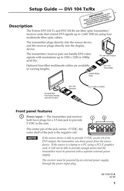
Description<br />
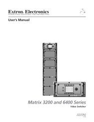
The <strong>Extron</strong> <strong>DVI</strong> <strong>104</strong> <strong>Tx</strong> and <strong>DVI</strong> <strong>104</strong> <strong>Rx</strong> are fiber optic transmitter/<br />
receiver units that extend <strong>DVI</strong> signals up to 1,640' (500 m) using four<br />
multimode fiber optic cables.<br />
The transmitter plugs directly into the source device<br />
and the receiver plugs directly into the display<br />
device.<br />
The transmitter/receiver pair can handle <strong>DVI</strong> video<br />
signals with resolutions up to 1920 x 1200 or 1080p<br />
at 60 Hz.<br />
Optional four-fiber multimode cables are available<br />
in varying lengths.<br />
Hi-resolution<br />
Flat Panel Display<br />
with <strong>DVI</strong>-D Input<br />
Front panel features<br />
a<br />
<strong>Setup</strong> <strong>Guide</strong> — <strong>DVI</strong> <strong>104</strong> <strong>Tx</strong>/<strong>Rx</strong><br />
<strong>DVI</strong> <strong>104</strong><br />
Receiver<br />
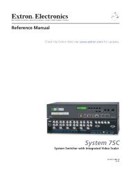
Power input — The transmitter and receiver<br />
both have plugs for a 3.5 mm jack to provide<br />
5 VDC to the unit.<br />
The center pin of the jack carries +5 VDC; the<br />
outer shell of the jack is the negative rail.<br />
4 Multi Mode<br />
Fiber<br />
Up to 500 m (1640')<br />
1 2<br />
PC with <strong>DVI</strong> Output<br />
<strong>DVI</strong> <strong>104</strong><br />
Transmitter<br />
N If the source device is able to provide 5 VDC on pin 14 of its<br />
<strong>DVI</strong> output, the transmitter can draw power from the source<br />
device. If the source is a laptop or a PC using a PCI-E graphics<br />
card, it will not be able to provide enough power and the<br />
transmitter must be powered with a separate external power<br />
supply.<br />
The receiver must be powered by an external power supply<br />
through the power input plug.<br />
68-1549-50 A<br />
02 09<br />
1
2<br />
<strong>Setup</strong> <strong>Guide</strong> — <strong>DVI</strong> <strong>104</strong> <strong>Tx</strong>/<strong>Rx</strong>, (cont’d)<br />
b<br />
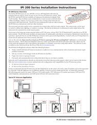
LC Jacks — Four fiber optic cables connect the transmitter to the<br />
receiver. The cables connect to the four female LC jacks in each of the<br />
units.<br />
A label on the top panel identifies the unit as the transmitter or receiver<br />
and identifies the fiber optic port numbers and the power input.<br />
N For the transmitter, port 1 is closest to the power input and<br />
port 4 is furthest away. For the receiver, port 4 is closest to the<br />
power input and port 1 is furthest away.<br />
Although the orientation is reversed, ports with the same<br />
number must be connected by the same cable, so that port 1 on<br />
the receiver is connected to port 1 on the transmitter, etcetera.<br />
Insert the end of the fiber optic cable into the appropriate plug on the<br />
transmitter or receiver. The locking catch should snap into the slot and<br />
hold the cable securely in place.<br />
Top panel features<br />
c<br />
d<br />
LED — Both the transmitter and<br />
receiver have LEDs on both sides<br />
that light blue when the unit is<br />
receiving power. The LEDs on<br />
the transmitter also function as<br />
a status indicator for the EDID<br />
minder feature (see “<strong>Setup</strong> and<br />
Operation”).<br />
Thumbscrews — Use the<br />
thumbscrews to secure the<br />
transmitter or receiver to its<br />
connector.<br />
Side panel features (transmitter only)<br />
e<br />
3 4<br />
EDID Minder storage button<br />
(transmitter only) — A recessed<br />
switch activates the transmitter<br />
to capture and store EDID<br />
information from the display<br />
5<br />
device. This allows the source<br />
device to provide a signal with a resolution and refresh rate matching<br />
the needs of the display device. (For more information, see the next<br />
section, “<strong>Setup</strong> and Operation”.)
<strong>Setup</strong> and Operation<br />
When using the <strong>DVI</strong> <strong>104</strong> <strong>Tx</strong>/<strong>Rx</strong> for the first time or if the display<br />
device is changed, it is essential to set up the EDID Minder. The setup<br />
process places EDID information on a EEPROM chip in the transmitter,<br />
which allows the video source to boot up correctly. This process is<br />
described below in steps 1-6. If you have already set up the EDID<br />
Minder, proceed to step 7.<br />
1. Ensure that the source, the display, the transmitter, and the<br />
receiver are all powered off and that the fiber optic cables are<br />
unplugged from the transmitter and the receiver.<br />
2. Apply power to the transmitter by inserting the cable from the<br />
external power supply into the input jack. The LEDs light a solid<br />
blue.<br />
3. Gently press and release the EDID Minder storage button, using<br />
a pointed device, such as a paper clip. Both LEDs should blink<br />
twice and turn off, although power is still connected.<br />
4. Power on the display device.<br />
5. Connect the transmitter directly to the <strong>DVI</strong> input of the<br />
display device. The LEDs on the transmitter blink rapidly for<br />
a few seconds to indicate that it is reading and storing EDID<br />
information from the display device.<br />
When the information has been captured and stored, the LEDs<br />
stop blinking. They may light steadily or they may turn off,<br />
depending on the display device.<br />
N The transmitter must remain connected to both the display<br />
device and the power supply for the entire time that the EDID<br />
capture is taking place<br />
6. Once the capture and storage are complete and the LEDs are no<br />
longer blinking, disconnect the transmitter from both the power<br />
and the display device.<br />
N Once the transmitter has captured the EDID information from<br />
the display device, the information is stored on an EEPROM<br />
chip in the transmitter. Therefore, this calibration needs to<br />
be performed only once, as long as the display device is not<br />
changed.<br />
If the display device is changed, repeat steps 1-6 to capture<br />
and store the EDID information for the new device.<br />
7. Apply power to the receiver. The LEDs illuminate steadily.<br />
3
8. Ensure that the display device is still powered on, connect the<br />
receiver directly to the <strong>DVI</strong> input, and tighten the thumbscrews.<br />
9. Ensure that the PC or source is powered off, connect the<br />
transmitter directly to the source’s <strong>DVI</strong> input, and tighten the<br />
thumbscrews.<br />
10. If required, apply power to the transmitter. The LEDs illuminate<br />
steadily.<br />
11. Connect all four fiber optic cables between the transmitter and<br />
receiver. Pay attention to the orientation of the LC connectors<br />
and ensure that each cable joins ports with the same number (port<br />
1 of the transmitter must be connected to port 1 of the receiver,<br />
etcetera.)<br />
<strong>Extron</strong><br />
33-1641-01<br />
Rev. A 05 08<br />
TO COMPUTER (<strong>Tx</strong>)<br />
PN 60-977-12<br />
5 V 1 2 3 4<br />
www.extron.com<br />
2<br />
1<br />
3<br />
4<br />
<strong>Extron</strong><br />
33-1642-01<br />
Rev. A 05 08<br />
TO DISPLAY (<strong>Rx</strong>)<br />
PN 60-977-13<br />
5 V 4 3 2 1<br />
12. Turn on the source device. The source device reads the<br />
information stored in the transmitter and boots up to that<br />
resolution and refresh rate.<br />
www.extron.com<br />
4
5<br />
Troubleshooting<br />
Display does not show an image<br />
•<br />
•<br />
•<br />
•<br />
•<br />
•<br />
Ensure that all plugs and jacks used by the external power<br />
supplies are firmly connected.<br />
Ensure that the LEDs for both the transmitter and receiver are lit.<br />
Ensure that the correct EDID information has been stored on the<br />
transmitter’s EDID Minder. When using the<br />
<strong>DVI</strong> <strong>104</strong> <strong>Tx</strong>/<strong>Rx</strong> for the first time or if the display device is<br />
changed, it is essential to set up the EDID Minder as described in<br />
steps 1-6 of “<strong>Setup</strong> and Operation” on page 3 of this guide.<br />
Ensure that the source device and output device are powered on<br />
and have booted up correctly.<br />
Ensure that the fiber optic cables are connecting the correct<br />
ports. A port on the transmitter must be connected to the same<br />
numbered port on the receiver. For example, port 1 of the<br />
transmitter must be connected to port 1 of the receiver.<br />
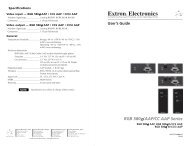
Ensure that the fiber optic cable jacks are securely seated.<br />
If the cable is loose or slips out of the slot easily, move the release<br />
catch from its normal position above the locking catch, to the<br />
adjusted position under the locking catch (see the figure below).<br />
This provides the extra leverage required to keep the locking catch<br />
in place and hold the cable securely.<br />
Locking catch Release catch<br />
Normal Position<br />
Adjusted Position
•<br />
•<br />
•<br />
Ensure that the transmitter is firmly plugged into the source<br />
device and the receiver is firmly plugged into the output device.<br />
Try resetting the system by unplugging and reconnecting the <strong>DVI</strong><br />
connectors or the power jacks.<br />
Try rebooting the computer.<br />
Screen is distorted or displays noise<br />
<strong>Extron</strong> USA - West<br />
Headquarters<br />
+800.633.9876<br />
Inside USA / Canada Only<br />
+1.714.491.1500<br />
+1.714.491.1517 FAX<br />
• Ensure that the cable length does not exceed 1,640' (500 m).<br />
• Ensure that the cables are high quality multimode cable and are<br />
terminated with securely fitting plugs.<br />
•<br />
•<br />
•<br />
Ensure that the resolution is correctly set, using the EDID Minder<br />
(see “<strong>Setup</strong> and Operation”).<br />
View the “Display Properties” of the source device to check the<br />
output resolution. The resolution and refresh rate must match the<br />
capabilities of the display device and must not exceed 1920 x 1200<br />
at 60 Hz.<br />
Try resetting the system by unplugging and reconnecting the <strong>DVI</strong><br />
connectors or the power jacks.<br />
<strong>Extron</strong> USA - East<br />
+800.633.9876<br />
Inside USA / Canada Only<br />
+1.919.863.1794<br />
+1.919.863.1797 FAX<br />
<strong>Extron</strong> Europe<br />
+800.3987.6673<br />
Inside Europe Only<br />
+31.33.453.4040<br />
+31.33.453.4050 FAX<br />
<strong>Extron</strong> Asia<br />
+800.7339.8766<br />
Inside Asia Only<br />
+65.6383.4400<br />
+65.6383.4664 FAX<br />
<strong>Extron</strong> Japan<br />
+81.3.3511.7655<br />
+81.3.3511.7656 FAX<br />
© 2009 <strong>Extron</strong> <strong>Electronics</strong>. All rights reserved.<br />
<strong>Extron</strong> China<br />
+400.883.1568<br />
Inside China Only<br />
+86.21.3760.1568<br />
+86.21.3760.1566 FAX<br />
<strong>Extron</strong> Middle East<br />
+971.4.2991800<br />
+971.4.2991880 FAX<br />
6