68-757-01, rev. D, full manual - Extron Electronics
68-757-01, rev. D, full manual - Extron Electronics
68-757-01, rev. D, full manual - Extron Electronics

You also want an ePaper? Increase the reach of your titles
YUMPU automatically turns print PDFs into web optimized ePapers that Google loves.
User’s Manual<br />
PRELIMINARY<br />
DAV1<strong>01</strong>CM Series, DAS1<strong>01</strong>CM Series<br />
VGA Line Drivers and Audio Buffers<br />
<strong>68</strong>-<strong>757</strong>-<strong>01</strong> Rev. D<br />
11 08
Precautions<br />
Safety Instructions • English<br />
This symbol is intended to alert the user of important<br />
operating and maintenance (servicing) instructions in<br />
the literature provided with the equipment.<br />
This symbol is intended to alert the user of the<br />
presence of uninsulated dangerous voltage within<br />
the product’s enclosure that may present a risk of<br />
electric shock.<br />
Caution<br />
Read Instructions • Read and understand all safety and operating<br />
instructions before using the equipment.<br />
Retain Instructions • The safety instructions should be kept for future<br />
reference.<br />
Follow Warnings • Follow all warnings and instructions marked on the<br />
equipment or in the user information.<br />
Avoid Attachments • Do not use tools or attachments that are not<br />
recommended by the equipment manufacturer because they may be<br />
hazardous.<br />
Consignes de Sécurité • Français<br />
Ce symbole sert à avertir l’utilisateur que la<br />
documentation fournie avec le matériel contient des<br />
instructions importantes concernant l’exploitation et<br />
la maintenance (réparation).<br />
Ce symbole sert à avertir l’utilisateur de la présence<br />
dans le boîtier de l’appareil de tensions dangereuses<br />
non isolées posant des risques d’électrocution.<br />
Attention<br />
Lire les instructions• Prendre connaissance de toutes les consignes de<br />
sécurité et d’exploitation avant d’utiliser le matériel.<br />
Conserver les instructions• Ranger les consignes de sécurité afin de pouvoir<br />
les consulter à l’avenir.<br />
Respecter les avertissements • Observer tous les avertissements et consignes<br />
marqués sur le matériel ou présentés dans la documentation utilisateur.<br />
Eviter les pièces de fixation • Ne pas utiliser de pièces de fixation ni d’outils<br />
non recommandés par le fabricant du matériel car cela risquerait de poser<br />
certains dangers.<br />
Sicherheitsanleitungen • Deutsch<br />
Dieses Symbol soll dem Benutzer in der im<br />
Lieferumfang enthaltenen Dokumentation<br />
besonders wichtige Hinweise zur Bedienung und<br />
Wartung (Instandhaltung) geben.<br />
Dieses Symbol soll den Benutzer darauf aufmerksam<br />
machen, daß im Inneren des Gehäuses dieses<br />
Produktes gefährliche Spannungen, die nicht isoliert<br />
sind und die einen elektrischen Schock verursachen<br />
können, herrschen.<br />
Achtung<br />
Lesen der Anleitungen • Bevor Sie das Gerät zum ersten Mal verwenden,<br />
sollten Sie alle Sicherheits-und Bedienungsanleitungen genau durchlesen<br />
und verstehen.<br />
Aufbewahren der Anleitungen • Die Hinweise zur elektrischen Sicherheit<br />
des Produktes sollten Sie aufbewahren, damit Sie im Bedarfsfall darauf<br />
zurückgreifen können.<br />
Befolgen der Warnhinweise • Befolgen Sie alle Warnhinweise und<br />
Anleitungen auf dem Gerät oder in der Benutzerdokumentation.<br />
Keine Zusatzgeräte • Verwenden Sie keine Werkzeuge oder Zusatzgeräte,<br />
die nicht ausdrücklich vom Hersteller empfohlen wurden, da diese eine<br />
Gefahrenquelle darstellen können.<br />
Instrucciones de seguridad • Español<br />
Este símbolo se utiliza para advertir al usuario<br />
sobre instrucciones importantes de operación y<br />
mantenimiento (o cambio de partes) que se desean<br />
destacar en el contenido de la documentación<br />
suministrada con los equipos.<br />
Este símbolo se utiliza para advertir al usuario sobre<br />
la presencia de elementos con voltaje peligroso sin<br />
protección aislante, que puedan encontrarse dentro<br />
de la caja o alojamiento del producto, y que puedan<br />
representar riesgo de electrocución.<br />
Precaucion<br />
Leer las instrucciones • Leer y analizar todas las instrucciones de operación y<br />
seguridad, antes de usar el equipo.<br />
Conservar las instrucciones • Conservar las instrucciones de seguridad para<br />
futura consulta.<br />
Obedecer las advertencias • Todas las advertencias e instrucciones marcadas<br />
en el equipo o en la documentación del usuario, deben ser obedecidas.<br />
Evitar el uso de accesorios • No usar herramientas o accesorios que no<br />
sean especificamente recomendados por el fabricante, ya que podrian<br />
implicar riesgos.<br />
Warning<br />
Power sources • This equipment should be operated only from the power source<br />
indicated on the product. This equipment is intended to be used with a main power<br />
system with a grounded (neutral) conductor. The third (grounding) pin is a safety<br />
feature, do not attempt to bypass or disable it.<br />
Power disconnection • To remove power from the equipment safely, remove all power<br />
cords from the rear of the equipment, or the desktop power module (if detachable),<br />
or from the power source receptacle (wall plug).<br />
Power cord protection • Power cords should be routed so that they are not likely to be<br />
stepped on or pinched by items placed upon or against them.<br />
Servicing • Refer all servicing to qualified service personnel. There are no userserviceable<br />
parts inside. To p<strong>rev</strong>ent the risk of shock, do not attempt to service<br />
this equipment yourself because opening or removing covers may expose you to<br />
dangerous voltage or other hazards.<br />
Slots and openings • If the equipment has slots or holes in the enclosure, these are<br />
provided to p<strong>rev</strong>ent overheating of sensitive components inside. These openings<br />
must never be blocked by other objects.<br />
Lithium battery • There is a danger of explosion if battery is incorrectly<br />
replaced. Replace it only with the same or equivalent type recommended by<br />
the manufacturer. Dispose of used batteries according to the manufacturer’s<br />
instructions.<br />
Avertissement<br />
Alimentations• Ne faire fonctionner ce matériel qu’avec la source d’alimentation<br />
indiquée sur l’appareil. Ce matériel doit être utilisé avec une alimentation principale<br />
comportant un fil de terre (neutre). Le troisième contact (de mise à la terre) constitue<br />
un dispositif de sécurité : n’essayez pas de la contourner ni de la désactiver.<br />
Déconnexion de l’alimentation• Pour mettre le matériel hors tension sans danger,<br />
déconnectez tous les cordons d’alimentation de l’arrière de l’appareil ou du module<br />
d’alimentation de bureau (s’il est amovible) ou encore de la prise secteur.<br />
Protection du cordon d’alimentation • Acheminer les cordons d’alimentation de<br />
manière à ce que personne ne risque de marcher dessus et à ce qu’ils ne soient pas<br />
écrasés ou pincés par des objets.<br />
Réparation-maintenance • Faire exécuter toutes les interventions de réparationmaintenance<br />
par un technicien qualifié. Aucun des éléments internes ne peut être<br />
réparé par l’utilisateur. Afin d’éviter tout danger d’électrocution, l’utilisateur ne doit<br />
pas essayer de procéder lui-même à ces opérations car l’ouverture ou le retrait des<br />
couvercles risquent de l’exposer à de hautes tensions et autres dangers.<br />
Fentes et orifices • Si le boîtier de l’appareil comporte des fentes ou des orifices, ceux-ci<br />
servent à empêcher les composants internes sensibles de surchauffer. Ces ouvertures<br />
ne doivent jamais être bloquées par des objets.<br />
Lithium Batterie • Il a danger d’explosion s’ll y a remplacment incorrect de la batterie.<br />
Remplacer uniquement avec une batterie du meme type ou d’un ype equivalent<br />
recommande par le constructeur. Mettre au reut les batteries usagees conformement<br />
aux instructions du fabricant.<br />
Vorsicht<br />
Stromquellen • Dieses Gerät sollte nur über die auf dem Produkt angegebene<br />
Stromquelle betrieben werden. Dieses Gerät wurde für eine Verwendung mit einer<br />
Hauptstromleitung mit einem geerdeten (neutralen) Leiter konzipiert. Der dritte<br />
Kontakt ist für einen Erdanschluß, und stellt eine Sicherheitsfunktion dar. Diese<br />
sollte nicht umgangen oder außer Betrieb gesetzt werden.<br />
Stromunterbrechung • Um das Gerät auf sichere Weise vom Netz zu trennen, sollten<br />
Sie alle Netzkabel aus der Rückseite des Gerätes, aus der externen Stomversorgung<br />
(falls dies möglich ist) oder aus der Wandsteckdose ziehen.<br />
Schutz des Netzkabels • Netzkabel sollten stets so verlegt werden, daß sie nicht im<br />
Weg liegen und niemand darauf treten kann oder Objekte darauf- oder unmittelbar<br />
dagegengestellt werden können.<br />
Wartung • Alle Wartungsmaßnahmen sollten nur von qualifiziertem Servicepersonal<br />
durchgeführt werden. Die internen Komponenten des Gerätes sind wartungsfrei.<br />
Zur Vermeidung eines elektrischen Schocks versuchen Sie in keinem Fall, dieses<br />
Gerät selbst öffnen, da beim Entfernen der Abdeckungen die Gefahr eines<br />
elektrischen Schlags und/oder andere Gefahren bestehen.<br />
Schlitze und Öffnungen • Wenn das Gerät Schlitze oder Löcher im Gehäuse aufweist,<br />
dienen diese zur Vermeidung einer Überhitzung der empfindlichen Teile im<br />
Inneren. Diese Öffnungen dürfen niemals von anderen Objekten blockiert werden.<br />
Litium-Batterie • Explosionsgefahr, falls die Batterie nicht richtig ersetzt<br />
wird. Ersetzen Sie verbrauchte Batterien nur durch den gleichen oder einen<br />
vergleichbaren Batterietyp, der auch vom Hersteller empfohlen wird. Entsorgen Sie<br />
verbrauchte Batterien bitte gemäß den Herstelleranweisungen.<br />
Advertencia<br />
Alimentación eléctrica • Este equipo debe conectarse únicamente a la fuente/tipo<br />
de alimentación eléctrica indicada en el mismo. La alimentación eléctrica de este<br />
equipo debe provenir de un sistema de distribución general con conductor neutro<br />
a tierra. La tercera pata (puesta a tierra) es una medida de seguridad, no puentearia<br />
ni eliminaria.<br />
Desconexión de alimentación eléctrica • Para desconectar con seguridad la acometida<br />
de alimentación eléctrica al equipo, desenchufar todos los cables de alimentación<br />
en el panel trasero del equipo, o desenchufar el módulo de alimentación (si fuera<br />
independiente), o desenchufar el cable del receptáculo de la pared.<br />
Protección del cables de alimentación • Los cables de alimentación eléctrica se deben<br />
instalar en lugares donde no sean pisados ni apretados por objetos que se puedan<br />
apoyar sobre ellos.<br />
Reparaciones/mantenimiento • Solicitar siempre los servicios técnicos de personal<br />
calificado. En el interior no hay partes a las que el usuario deba acceder. Para evitar<br />
riesgo de electrocución, no intentar personalmente la reparación/mantenimiento<br />
de este equipo, ya que al abrir o extraer las tapas puede quedar expuesto a voltajes<br />
peligrosos u otros riesgos.<br />
Ranuras y aberturas • Si el equipo posee ranuras o orificios en su caja/alojamiento,<br />
es para evitar el sobrecalientamiento de componentes internos sensibles. Estas<br />
aberturas nunca se deben obstruir con otros objetos.<br />
Batería de litio • Existe riesgo de explosión si esta batería se coloca en la posición<br />
incorrecta. Cambiar esta batería únicamente con el mismo tipo (o su equivalente)<br />
recomendado por el fabricante. Desachar las baterías usadas siguiendo las<br />
instrucciones del fabricante.
安全须知 • 中文<br />
这个符号提示用户该设备用户手册中<br />
有重要的操作和维护说明。<br />
这个符号警告用户该设备机壳内有暴<br />
露的危险电压,有触电危险。<br />
注意<br />
阅读说明书 • 用户使用该设备前必须阅读并理<br />
解所有安全和使用说明。<br />
保存说明书 • 用户应保存安全说明书以备将来使<br />
用。<br />
遵守警告 • 用户应遵守产品和用户指南上的所有安<br />
全和操作说明。<br />
避免追加 • 不要使用该产品厂商没有推荐的工具或<br />
追加设备,以避免危险。<br />
FCC Class A Notice<br />
警告<br />
电源 • 该设备只能使用产品上标明的电源。 设备<br />
必须使用有地线的供电系统供电。 第三条线<br />
(地线)是安全设施,不能不用或跳过。<br />
拔掉电源 • 为安全地从设备拔掉电源,请拔掉所有设备后<br />
或桌面电源的电源线,或任何接到市电系统的电源线。<br />
电源线保护 • 妥善布线, 避免被踩踏,或重物挤压。<br />
维护 • 所有维修必须由认证的维修人员进行。 设备内部没<br />
有用户可以更换的零件。为避免出现触电危险不要自己<br />
试图打开设备盖子维修该设备。<br />
通风孔 • 有些设备机壳上有通风槽或孔,它们是用来防止<br />
机内敏感元件过热。 不要用任何东西挡住通风孔。<br />
锂电池 • 不正确的更换电池会有爆炸的危险。 必须使用与<br />
厂家推荐的相同或相近型号的电池。 按照生产厂的建<br />
议处理废弃电池。<br />
This equipment has been tested and found to comply with the limits for a Class A digital device,<br />
pursuant to part 15 of the FCC Rules. Operation is subject to the following two conditions: (1) this<br />
device may not cause harmful interference, and (2) this device must accept any interference received,<br />
including interference that may cause undesired operation. The Class A limits are designed to<br />
provide reasonable protection against harmful interference when the equipment is operated in<br />
a commercial environment. This equipment generates, uses, and can radiate radio frequency<br />
energy and, if not installed and used in accordance with the instruction <strong>manual</strong>, may cause harmful<br />
interference to radio communications. Operation of this equipment in a residential area is likely to<br />
cause harmful interference, in which case the user will be required to correct the interference at his<br />
own expense.<br />
N This unit was tested with shielded cables on the peripheral devices. Shielded cables must be used<br />
with the unit to ensure compliance with FCC emissions limits.<br />
DAV1<strong>01</strong>CM, DAS1<strong>01</strong>CM • Safety and Compliances
DAV1<strong>01</strong>CM, DAS1<strong>01</strong>CM • Safety and Compliances
Quick Start — DAV/DAS1<strong>01</strong>CM Series<br />
C Installation and service must be performed by authorized<br />
personnel only. These units must be installed in<br />
accordance with national and local electrical codes.<br />
To install the DAV1<strong>01</strong>CM and DAS1<strong>01</strong>CM modules, see the<br />
appropriate section of this <strong>manual</strong> and follow these steps:<br />
Step 1<br />
Install an electrical box or wall bracket (if applicable) and cables.<br />
Use cable clamps to hold cables in place for strain relief. Trim back<br />
or insulate exposed cable shields with heat shrink to p<strong>rev</strong>ent short<br />
circuits. See pages 2-2 to 2-3.<br />
Step 2<br />
Attach cables to the rear panel. Ensure that power and output cables<br />
have been fed through the wallbox/furniture and out the front of the<br />
faceplate, frame, or panel. Connect modules to each other (if<br />
applicable) and to the power supply, but do not apply power yet.<br />
Balanced<br />
Stereo Output Wiring<br />
12VDC<br />
0.1 A<br />
DAS1<strong>01</strong>CM-1/-2/-5<br />
Bottom View<br />
Power In<br />
Unbalanced<br />
Stereo Output Wiring<br />
12VDC<br />
0.1 A<br />
DAS1<strong>01</strong>CM-3/-4/-6<br />
Right, ring, –<br />
See caution.<br />
Right, tip, +<br />
Right, tip, +<br />
Ground, sleeve(s), Gnd, sleeve(s),<br />
Left, ring, –<br />
See caution.<br />
Left, tip, +<br />
Left, tip, +<br />
Connect output cables.<br />
See the diagrams here<br />
and on pages 2-4 to 2-6.<br />
C For unbalanced output, connect the sleeve to ground<br />
(Gnd, _). Connecting the sleeve to a negative (-) terminal<br />
will damage the audio output circuits.<br />
C The pin assignments of the DAS’s power input and power<br />
loop-through ports are different from those of the<br />
TECHNICAL SUPPORT:<br />
800.633.9876<br />
714.491.1500<br />
www.extron.com<br />
MADE IN USA<br />
+<br />
POWER IN<br />
12V @0.3A<br />
IN OUT<br />
12 VDC, 1 A<br />
DC Power<br />
Adapter<br />
DAV1<strong>01</strong>CM<br />
(back view)<br />
DAS1<strong>01</strong>CM<br />
(back view)<br />
Loop Out to DAV1<strong>01</strong>CM or CIA Interface<br />
N The channels of the<br />
DAS1<strong>01</strong>CM-3/-4<br />
are <strong>rev</strong>ersed (R-L<br />
instead of L-R)<br />
relative to the<br />
DAS1<strong>01</strong>CM-1/-2.<br />
DAV’s power input.<br />
Double-check your<br />
work against the wiring<br />
diagrams. Power wires must<br />
be attached to the correct<br />
terminals on each connector<br />
or these products can be<br />
damaged.<br />
DAV1<strong>01</strong>CM, DAS1<strong>01</strong>CM • Quick Start Guide<br />
iii
iv<br />
Quick Start Guide — DAV/DAS1<strong>01</strong>CM, cont’d<br />
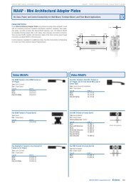
Step 3<br />
For wall/furniture or rack installations, attach the module(s) to a<br />
CPM Series mini architectural adapter plate (MAAP) frame or to a<br />
rack-mountable frame. See pages 2-3 and 2-4.<br />
Step 4<br />
Attach the front panel input cable(s).<br />
Step 5<br />
Verify correct cabling and connector wiring and test the system:<br />
power on all the devices and monitor the audio/video output.<br />
Each DAV module’s Power LED is lit while the unit receives power.<br />
If needed, power off the devices, disconnect the<br />
modules’ power supply, correct cabling or wiring<br />
errors, then restore power.<br />
Step 6<br />
For a DAV1<strong>01</strong>CM, set the sharpness/peaking<br />
control using a small screwdriver, as shown at<br />
right. See page 2–8.<br />
Step 7<br />
Disconnect power from the module(s) and<br />
other devices.<br />
Step 8<br />
For wall or furniture mounting, mount the<br />
modular connector frame and module(s) to<br />
the wall or furniture.<br />
For device mounting, mount the module(s) to the device’s faceplate.<br />
For rack mounting, mount the rack-mountable frame to the<br />
equipment rack.<br />
See pages 2-9 and 2-10. For all installations, place the connector plate<br />
onto/against the mounting surface and secure it to wall, furniture,<br />
device, or rack with the provided screws or bolts. Be careful not to<br />
damage the cables.<br />
Step 9<br />
Restore power to the devices. You have completed the installation.<br />
DAV1<strong>01</strong>CM, DAS1<strong>01</strong>CM • Quick Start Guide<br />
PEAKING<br />
DAV1<strong>01</strong>CM VGA LINE DRIVER<br />
VIDEO INPUT<br />
Peaking<br />
POWER
Table of Contents<br />
Chapter One • Introduction .................................................... 1-1<br />
About this Manual .................................................................... 1-2<br />
About the DAV/DAS1<strong>01</strong>CM Series ....................................... 1-2<br />
Features ........................................................................................ 1-2<br />
DAV1<strong>01</strong>CM Series................................................................... 1-3<br />
DAS1<strong>01</strong>CM Series ................................................................... 1-3<br />
Chapter Two • Installation and Operation ................... 2-1<br />
Installing a Wall Box or Wall Bracket ................................. 2-2<br />
Mounting the Module Into a Connector Module Frame<br />
or Rack-mountable Frame ....................................................... 2-3<br />
Rear Panel Features and Cabling .......................................... 2-4<br />
DAV1<strong>01</strong>CM Series................................................................... 2-4<br />
DAS1<strong>01</strong>CM Series, and DAV-DAS interconnection .............. 2-5<br />
Front Panel Features and Cabling ........................................ 2-7<br />
DAV1<strong>01</strong>CM Series................................................................... 2-7<br />
DAS1<strong>01</strong>CM Series ................................................................... 2-7<br />
Adjusting Sharpness (DAV Modules)
Table of Contents, cont’d<br />
ii DAV1<strong>01</strong>CM, DAS1<strong>01</strong>CM • Table of Contents
DAV1<strong>01</strong>CM, DAS1<strong>01</strong>CM<br />
1<br />
Chapter One<br />
Introduction<br />
About This Manual<br />
About the DAV/DAS1<strong>01</strong>CM Series<br />
Features
Introduction<br />
1-2<br />
About this Manual<br />
This <strong>manual</strong> contains information about the <strong>Extron</strong> DAV1<strong>01</strong>CM<br />
VGA–QXGA line drivers and DAS1<strong>01</strong>CM Series audio buffers<br />
and on how to install them.<br />
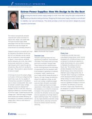
About the DAV/DAS1<strong>01</strong>CM Series<br />
The <strong>Extron</strong> DAV1<strong>01</strong>CM Series modules are compact, one input,<br />
one output, 400 MHz (-3 dB) bandwidth, VGA–QXGA line<br />
drivers that amplify the signal from a laptop, desktop, or other<br />
computer-video source. Each DAV1<strong>01</strong>CM module buffers and<br />
equalizes RGB and sync signals so they can be output on one set<br />
of five BNC connectors (DAV1<strong>01</strong>CM-3, -4, or -6) or one 15-pin<br />
HD connector (DAV1<strong>01</strong>CM-1, -2, or -5) and sent 150 feet or more<br />
on <strong>Extron</strong> Mini HR cable.<br />
The <strong>Extron</strong> DAS1<strong>01</strong>CM Series modules are compact audio<br />
buffers. Each module accepts one unbalanced audio input (on<br />
either a 3.5 mm mini tip-ringsleeve<br />
jack [DAS1<strong>01</strong>CM-1,<br />
-2, or -5] or on a pair of<br />
RCA connectors<br />
[DAS1<strong>01</strong>CM-3,<br />
-4, or -6]) and<br />
provides one<br />
balanced or<br />
unbalanced<br />
audio output<br />
(on a 3.5 mm,<br />
5-pole captive<br />
screw<br />
connector).<br />
A typical<br />
application<br />
<strong>Extron</strong><br />
CPM1<strong>01</strong><br />
Frame<br />
Laptop<br />
Features<br />
Compact design and light weight — These modules can be<br />
easily packed into a laptop case, portable projector case,<br />
or technician’s tool kit.<br />
DAV1<strong>01</strong>CM, DAS1<strong>01</strong>CM • Introduction<br />
DAV1<strong>01</strong>CM VGA Line Driver<br />
Power<br />
Video Input<br />
DAS1<strong>01</strong>CM Audio Buffer<br />
Projector<br />
<strong>Extron</strong><br />
DAV1<strong>01</strong>CM<br />
VGA Line Driver<br />
<strong>Extron</strong><br />
DAS1<strong>01</strong>CM-1<br />
Audio Buffer
Furniture- and rack-mountable design — The DAV/DAS1<strong>01</strong>CM<br />
modules can be mounted in a wall or<br />
furniture using a connector module<br />
frame and a junction box or a wall<br />
bracket. They can also be mounted in<br />
products with openings that<br />
accommodate this style of connector<br />
module or mounted to a CPM Series<br />
rack-mountable frame.<br />
Choice of colors — The modules are available with black, white,<br />
or RAL9<strong>01</strong>0 white faceplates.<br />
DAV1<strong>01</strong>CM Series<br />
DAV1<strong>01</strong>CM-3 (black) DAV1<strong>01</strong>CM-1 (black)<br />
-4 (white) -2 (white)<br />
-6 RAL 9<strong>01</strong>0) -5 (RAL9<strong>01</strong>0)<br />
Adjustable peaking control — High frequency equalization<br />
compensates for signal losses that occur in long cable<br />
runs. The DAV1<strong>01</strong>CM can drive signals for up to 150 feet<br />
of <strong>Extron</strong> Mini HR cable or 250 feet of <strong>Extron</strong> SHR cable.<br />
The variable sharpness control lets you select the best<br />
peaking setting for the resolution and cable length.<br />
Sync signal buffering with AGC — These modules provide<br />
sync signal buffering and automatic gain control (AGC)<br />
to restore sync signals to proper TTL levels for enhanced<br />
stability and reliability over extended cable runs.<br />
DAS1<strong>01</strong>CM Series<br />
DAS1<strong>01</strong>CM-1 (black) DAS1<strong>01</strong>CM-3 (black)<br />
-2 (white) -4 (white)<br />
-5 (RAL9<strong>01</strong>0) -6 (RAL9<strong>01</strong>0)<br />
Balanced or unbalanced audio output — Unbalanced, line<br />
level stereo audio inputs can be output as balanced or<br />
unbalanced stereo audio.<br />
Power loop-through for a paired DAV1<strong>01</strong>CM — A DAS1<strong>01</strong>CM<br />
can be mounted in a faceplate together with a DAV1<strong>01</strong>CM<br />
and share a single power supply so audio and computer<br />
DAV1<strong>01</strong>CM, DAS1<strong>01</strong>CM • Introduction<br />
1-3
Introduction, cont’d<br />
1-4<br />
video can be input, buffered, and driven from the same<br />
location.<br />
DAV1<strong>01</strong>CM, DAS1<strong>01</strong>CM • Introduction
DAV1<strong>01</strong>CM, DAS1<strong>01</strong>CM<br />
2<br />
Chapter Two<br />
Installation and Operation<br />
Installing a Wall Box or Wall Bracket<br />
Mounting the Module Into a Connector Module Frame<br />
or Rack-mountable Frame<br />
Rear Panel Features and Cabling<br />
Front Panel Features and Cabling<br />
Adjusting Sharpness (DAV Modules)<br />
Mounting the Modules
Installation and Operation<br />
2-2<br />
The DAV/DAS1<strong>01</strong>CM modules can be attached to a CPM<br />
mini architectural adapter plate (MAAP) mounting frame and<br />
mounted in a wall or furniture using either a one-gang wall<br />
box or a wall bracket. Alternatively they can be mounted in<br />
the chassis of a device (such as a CIA Series interface) that<br />
accommodates connector modules, or attached to a CPM Series<br />
rack-mountable frame for mounting in a standard equipment rack.<br />
Installing a Wall Box or Wall Bracket<br />
For wall and furniture mounting installations, the installation<br />
site must be deep enough for both the wall box (or the DAV/<br />
DAS, if using a wall bracket) and the cables. The box should be<br />
at least 2.5" (6.4 cm) deep. Install cables into the wall, furniture,<br />
or conduits before installing a wall box or bracket.<br />
1. Place the wall box or mounting bracket against the<br />
installation surface; mark the guidelines for the opening on<br />
the wall or furniture.<br />
2. Cut out the material from the marked area.<br />
3. Insert the wall box/bracket to check the opening’s size and<br />
fit. Enlarge or smooth the edges of the opening if needed.<br />
4. Feed cables through the wall box’s punch-out holes,<br />
ground shields, and<br />
secure cables with<br />
cable clamps to<br />
provide strain relief.<br />
Grounding shields<br />
}<br />
W To p<strong>rev</strong>ent<br />
short circuits, the<br />
Screw<br />
Braided<br />
Shield<br />
Cable<br />
Clamp<br />
Install<br />
Cable<br />
Foil Shield<br />
outer foil shield can be cut<br />
back to the point where the cable exits the cable clamp.<br />
Connect both braided and foil shields to an equipment<br />
ground at the other end of the cable. Insulate any<br />
exposed shields with heat shrink<br />
5. Insert the wall box or wall bracket into the opening, and<br />
attach it to the wall, stud, or furniture, leaving the front<br />
edge flush with the outer wall or furniture surface.<br />
To attach a wall box to wood, use four #8 or #10 screws or<br />
10-penny nails. A minimum of 1/2 inch (1.3 cm) of screw<br />
threads must penetrate the wood.<br />
To attach a wall box to metal, use four #8 or #10 self-tapping<br />
sheet metal screws or machine bolts with matching nuts.<br />
DAV1<strong>01</strong>CM, DAS1<strong>01</strong>CM • Installation and Operation<br />
Metal<br />
Wall<br />
Box
Wall Stud<br />
Installation<br />
Cable<br />
Cable Clamp<br />
1-gang wall box.eps<br />
Screws or Nails<br />
Wall opening<br />
is flush with<br />
edge of box.<br />
Attaching a wall box to a wall stud<br />
7. Mount the module(s) onto a mounting frame, then cable<br />
and test the DAV/DAS before fastening it into the wall box<br />
or bracket. The cables are inaccessible after installation.<br />
Mounting the Module Into a Connector<br />
Module Frame or Rack-mountable Frame<br />
For wall, furniture, or rack mounting installations. DAV and<br />
DAS modules must be attached to a faceplate, frame, or CPM<br />
Series rack-mountable frame and cabled before being installed.<br />
1. Insert the module into the faceplate's or frame’s opening.<br />
2. Secure the module to the<br />
faceplate or frame with the<br />
provided machine<br />
screws and nuts.<br />
INPUT<br />
SELECT POWER<br />
INPUT 1<br />
LOCAL MONITOR OUTPUT<br />
COMPUTER VIDEO INPUT<br />
CIA112 COMPUTER INTERFACE<br />
HORIZONTAL<br />
POSITION<br />
MONITOR<br />
EMULATION<br />
Attaching a DAS/DAV1<strong>01</strong>CM to a device’s faceplate<br />
DAV1<strong>01</strong>CM, DAS1<strong>01</strong>CM • Installation and Operation<br />
INPUT 2<br />
LOCAL MONITOR OUTPUT<br />
COMPUTER VIDEO INPUT<br />
AUDIO INPUT AUDIO INPUT<br />
PEAKING<br />
DAV1<strong>01</strong>CM VGA LINE DRIVER<br />
VIDEO INPUT<br />
POWER<br />
(4) #4 - 40<br />
Screws<br />
2-3
Installation and Operation, cont’d<br />
2-4<br />
DAV1<strong>01</strong>CM w CPM112R-1_10-16-03.eps<br />
CPM112R-1<br />
A/V Connector Panel<br />
PEAKING<br />
DAV1<strong>01</strong>CM VGA LINE DRIVER<br />
POWER<br />
VIDEO INPUT<br />
DAV1<strong>01</strong>CM VGA LINE DRIVER<br />
DAV1<strong>01</strong>CM, DAS1<strong>01</strong>CM • Installation and Operation<br />
PEAKING<br />
VIDEO INPUT<br />
POWER<br />
PEAKING PEAKING<br />
DAV1<strong>01</strong>CM VGA LINE DRIVER<br />
POWER<br />
VIDEO INPUT<br />
(4) #4 - 40<br />
Screws<br />
DAV1<strong>01</strong>CM VGA LINE DRIVER<br />
POWER<br />
VIDEO INPUT<br />
PEAKING<br />
DAV1<strong>01</strong>CM VGA LINE DRIVER<br />
POWER<br />
VIDEO INPUT<br />
PEAKING<br />
DAV1<strong>01</strong>CM VGA LINE DRIVER<br />
POWER<br />
VIDEO INPUT<br />
Attaching a DAS/DAV to a CPM rack-mountable frame<br />
Rear Panel Features and Cabling<br />
DAV1<strong>01</strong>CM Series<br />
DAV1<strong>01</strong>CM-1, -2, -5 DAV1<strong>01</strong>CM-3, -4, -6<br />
a<br />
TECHNICAL SUPPORT:<br />
800.633.9876<br />
714.491.1500<br />
www.extron.com<br />
MADE IN USA<br />
+<br />
POWER IN<br />
12V @0.3A<br />
1 1<br />
2<br />
TECHNICAL SUPPORT:<br />
800.633.9876<br />
714.491.1500<br />
www.extron.com<br />
MADE IN USA<br />
Power input — Connect a 12 VDC<br />
power supply directly to this two-pole<br />
direct insertion captive screw<br />
connector (see the diagram at right),<br />
or<br />
+<br />
POWER IN<br />
12V @0.3A<br />
+<br />
3
c<br />
connect the power supply to a DAS1<strong>01</strong>CM module’s 12 VDC<br />
In port and loop the power through to the DAV1<strong>01</strong>CM via the<br />
DAS1<strong>01</strong>CM’s 12 VDC Out port (see page 2-6).<br />
N Do not tin the stripped power supply leads before<br />
installing the captive screw connector.<br />
C Correct polarity is important! The power wires must<br />
be attached to the correct terminals or the module can<br />
be damaged.<br />
15-pin HD computer-video output (DAV1<strong>01</strong>CM-1, -2, -5) —<br />
Attach this connector to the display’s 15-pin HD input<br />
connector.<br />
BNC computer-video output (DAV1<strong>01</strong>CM-3, -4, -6) — Attach<br />
these five male BNC connectors to the display’s BNC input<br />
connectors.<br />
DAS1<strong>01</strong>CM Series, and DAV-DAS interconnection<br />
a<br />
b<br />
DAS1<strong>01</strong>CM-1, -2, -5<br />
Top View<br />
12VDC<br />
0.1 A<br />
DAS1<strong>01</strong>CM-3, -4, -6<br />
Top<br />
View<br />
12VDC<br />
0.1 A<br />
1 2 3 1 2 3<br />
DAS1<strong>01</strong>CM-1, -2, -5 Rear View DAS1<strong>01</strong>CM-3, -4, -6 Rear View<br />
12 VDC, 0.1 A In (power input) — Connect a 12VDC, 1 A power<br />
supply to these two poles of the DAS’s 4-pole direct insertion<br />
captive screw connector for power input.<br />
C Correct polarity is important! The power wires must<br />
be attached to the correct terminals or the module can<br />
be damaged.<br />
12 VDC, 0.1 A Out (power loop-through for DAV1<strong>01</strong>CM<br />
modules) — This port allows power to be looped through to a<br />
DAV1<strong>01</strong>CM. See the wiring diagram on the next page.<br />
DAV1<strong>01</strong>CM, DAS1<strong>01</strong>CM • Installation and Operation<br />
2-5
Installation and Operation, cont’d<br />
2-6<br />
c<br />
DAS1<strong>01</strong>CM-1/-2/-5<br />
Bottom View<br />
C The pin assignments of the DAS’s power input and<br />
power loop-through ports are different from those of<br />
the DAV modules’ power input. Double-check your<br />
work against the wiring diagram. Power wires must<br />
be attached to the correct terminals on each connector<br />
or these products can be damaged.<br />
Power In<br />
TECHNICAL SUPPORT:<br />
800.633.9876<br />
714.491.1500<br />
www.extron.com<br />
MADE IN USA<br />
+<br />
POWER IN<br />
12V @0.3A<br />
IN OUT<br />
12 VDC, 1 A<br />
DC Power<br />
Adapter<br />
DAV1<strong>01</strong>CM<br />
(back view)<br />
DAS1<strong>01</strong>CM<br />
(back view)<br />
Loop Out to DAV1<strong>01</strong>CM or CIA Interface<br />
DAV-DAS power interconnection<br />
Audio output — Wire this 5-pole, 3.5 mm, direct insertion<br />
captive screw connector as shown below for either balanced or<br />
unbalanced stereo audio output.<br />
Balanced<br />
Stereo Output Wiring<br />
12VDC<br />
0.1 A<br />
Unbalanced<br />
Stereo Output Wiring<br />
12VDC<br />
0.1 A<br />
DAS1<strong>01</strong>CM-3/-4/-6<br />
Right, ring, –<br />
See caution.<br />
Right, tip, +<br />
Right, tip, +<br />
Ground, sleeve(s), Gnd, sleeve(s),<br />
Left, ring, –<br />
See caution.<br />
Left, tip, +<br />
Left, tip, +<br />
N The left and right channels of the DAS1<strong>01</strong>CM-3/-4/-6 are<br />
<strong>rev</strong>ersed (R-L instead of L-R) relative to the<br />
DAS1<strong>01</strong>CM-1/-2/-5, as shown above.<br />
C For unbalanced output, connect the sleeve to ground<br />
(Gnd, _). Connecting the sleeve to a negative (-)<br />
terminal will damage the audio output circuits.<br />
DAV1<strong>01</strong>CM, DAS1<strong>01</strong>CM • Installation and Operation
Front Panel Features and Cabling<br />
DAV1<strong>01</strong>CM Series<br />
a<br />
b<br />
DAV1<strong>01</strong>CM VGA LINE DRIVER<br />
VIDEO INPUT<br />
POWER<br />
DAV1<strong>01</strong>CM VGA LINE DRIVER<br />
VIDEO INPUT<br />
DAV1<strong>01</strong>CM-3/-4/-6 DAV1<strong>01</strong>CM-1/-2/-5<br />
2<br />
1<br />
POWER<br />
Power LED — This indicator remains lit while the DAV is<br />
receiving power.<br />
Video Input — Connect a cable from the source computer to<br />
the DAV via this 15-pin HD connector, which provides ID bit<br />
termination on pins 4 and 11.<br />
DAS1<strong>01</strong>CM Series<br />
a<br />
b<br />
DAS1<strong>01</strong>CM-1, -2, -5 DAS1<strong>01</strong>CM-3, -4, -6<br />
DAS1<strong>01</strong>CM AUDIO BUFFER<br />
DAV1<strong>01</strong>CM, DAS1<strong>01</strong>CM • Installation and Operation<br />
2<br />
1<br />
DAS1<strong>01</strong>CM AUDIO BUFFER<br />
1 2 3<br />
Stereo audio input<br />
(DAS1<strong>01</strong>CM-1, -2, -5) — Connect an<br />
unbalanced, line level stereo audio<br />
source to this mini stereo jack using a<br />
3.5 mm tip-ring-sleeve connector wired<br />
as shown at right.<br />
,c Left and right audio inputs<br />
Tip (L)<br />
Ring (R)<br />
(DAS1<strong>01</strong>CM-3, -4, -6) — Connect an unbalanced, line level,<br />
stereo audio source to these RCA (tip-ring) jacks.<br />
Wire the plugs as shown in the following diagram.<br />
Sleeve ( )<br />
3.5 mm Stereo Plug<br />
(unbalanced)<br />
2-7
Installation and Operation, cont’d<br />
2-8<br />
Tip (Signal)<br />
Sleeve (Gnd )<br />
Audio RCA connector color.eps<br />
Tip (+)<br />
Sleeve ( )<br />
Right Channel<br />
(Red Jacket)<br />
Left Channel<br />
(White Jacket)<br />
RCA connector wiring for DAS1<strong>01</strong>CM-3,-04 audio input<br />
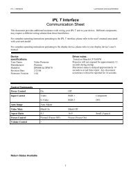
Adjusting Sharpness (DAV Modules)<br />
The longer the cable being used, the<br />
greater the signal loss. The DAV1<strong>01</strong>CMs<br />
have an adjustable sharpness/peaking<br />
control that equalizes the video signal<br />
to compensate for signal losses. The<br />
DAV1<strong>01</strong>CM can drive signals for up<br />
to 150 feet of <strong>Extron</strong> mini HR cable or<br />
250 feet of <strong>Extron</strong> SHR cable.<br />
While viewing the output image,<br />
use a small screwdriver to rotate this<br />
potentiometer to select the setting that<br />
gives the clearest pictures.<br />
C Using a larger screwdriver<br />
can break the potentiometer.<br />
Mounting the Modules<br />
Test the system. Adjust the sharpness (see "Adjusting<br />
Sharpness") or disconnect the power and correct any cabling or<br />
wiring errors before mounting the modules.<br />
C To avoid the risk of electrical shock, disconnect power<br />
from the DAV or DAS module before mounting it.<br />
For all installations, place the DAV’s or DAS’s faceplate (or the<br />
mounting frame it is attached to) onto/against the mounting<br />
surface and secure it with the provided screws or bolts. Be<br />
careful not to damage the cables.<br />
DAV1<strong>01</strong>CM, DAS1<strong>01</strong>CM • Installation and Operation<br />
PEAKING<br />
DAV1<strong>01</strong>CM VGA LINE DRIVER<br />
VIDEO INPUT<br />
Peaking<br />
POWER
DAV-DAS1<strong>01</strong>CM-1 w CPM1<strong>01</strong>_10-16-03.eps<br />
Wall/furniture mounting<br />
Mount the frame and module(s) to the wall or furniture, as<br />
shown below.<br />
DAV1<strong>01</strong>CM, DAS1<strong>01</strong>CM • Installation and Operation<br />
PEAKING<br />
(8) #4 - 40<br />
Screws<br />
DAV1<strong>01</strong>CM VGA LINE DRIVER<br />
Video Input<br />
Power<br />
DAS1<strong>01</strong>CM Audio Buffer<br />
2-9
Installation and Operation, cont’d<br />
2-10<br />
Device mounting<br />
Mount the module(s) to the device’s faceplate, as shown below.<br />
Rack mounting<br />
Mount the rack-mountable<br />
frame to the equipment<br />
rack as shown<br />
below.<br />
DAV1<strong>01</strong>CM Rack mount_10-16-03.eps<br />
DAV1<strong>01</strong>CM VGA LINE DRIVER<br />
VIDEO INPUT<br />
POWER<br />
DAV1<strong>01</strong>CM VGA LINE DRIVER<br />
DAV1<strong>01</strong>CM VGA LINE DRIVER<br />
DAV1<strong>01</strong>CM, DAS1<strong>01</strong>CM • Installation and Operation<br />
VIDEO INPUT<br />
POWER<br />
DAV1<strong>01</strong>CM VGA LINE DRIVER<br />
PEAKING PEAKING PEAKING<br />
VIDEO INPUT<br />
POWER<br />
DAV1<strong>01</strong>CM VGA LINE DRIVER<br />
VIDEO INPUT<br />
POWER<br />
PEAKING<br />
VIDEO INPUT<br />
DAV1<strong>01</strong>CM VGA LINE DRIVER<br />
POWER<br />
(4) #4 - 40<br />
Screws<br />
Restore power to the devices.<br />
You have completed the installation.<br />
VIDEO INPUT<br />
POWER<br />
PEAKING PEAKING PEAKING<br />
DAV1<strong>01</strong>CM VGA LINE DRIVER<br />
VIDEO INPUT<br />
POWER
DAV1<strong>01</strong>CM, DAS1<strong>01</strong>CM<br />
Appendix A<br />
Specifications, Part Numbers,<br />
and Accessories<br />
Specifications<br />
Included Parts<br />
Accessories<br />
Cables
Specifications, Part Numbers, and Accessories<br />
Specifications<br />
Video— DAV1<strong>01</strong>CM<br />
Gain ................................................. Unity<br />
Bandwidth ...................................... 400 MHz (-3 dB)<br />
Video input— DAV1<strong>01</strong>CM<br />
Number/signal type ..................... 1 VGA–QXGA RGBHV, RGBS, RGsB,<br />
RsGsBs, or HDTV component video<br />
Connectors ..................................... (1) 15-pin HD female<br />
Nominal level ................................ 1 Vp-p for Y of component video<br />
0.7 Vp-p for RGB and for R-Y and B-Y of<br />
component video<br />
Minimum/maximum levels ........ Analog: 0.3 V to 1.5 Vp-p with no offset<br />
Impedance ...................................... 75 ohms<br />
Horizontal frequency .................... 15 kHz to 175 kHz<br />
Vertical frequency .......................... 30 Hz to 150 Hz<br />
Return loss ......................................
Input impedance ........................... 510 ohms<br />
Output impedance ........................ +15 dBu, balanced or unbalanced at 1%<br />
THD+N<br />
Maximum level (600 ohm) ........... >+13 dBm, balanced or unbalanced at 1%<br />
THD+N<br />
DAV1<strong>01</strong>CM, DAS1<strong>01</strong>CM • Specifications, Part #s, Accessories<br />
A-3
Specifications, Part Numbers, Accessories, cont’d<br />
General<br />
External power supply ................. 100 VAC to 240 VAC, 50/60 Hz, 3 watts,<br />
external, to a 12 VDC, 1 A power supply<br />
(#70-055-<strong>01</strong> included for the DAV1<strong>01</strong>CM,<br />
optional for the DAS1<strong>01</strong>CM).<br />
Power input requirements<br />
DAV1<strong>01</strong>CM ........................ 12 VDC, 0.3 A<br />
DAS1<strong>01</strong>CM ......................... 12VDC, 0.1 A<br />
Temperature/humidity ................ Storage: -40 to +158 °F (-40 to +70 °C) /<br />
10% to 90%, noncondensing<br />
Operating: +32 to +113 °F (0 to +45 °C) /<br />
10% to 90%, noncondensing<br />
Cooling ........................................... Convection, unvented<br />
Rack mount .................................... Yes, with optional rack shelf and face<br />
plates. Also wall or furniture mountable<br />
with optional faceplates<br />
Enclosure type ............................... Metal<br />
Enclosure dimensions<br />
DAV1<strong>01</strong>CM<br />
Faceplate ..................... 1.4" H x 2.2" W x 0.1" D<br />
(3.6 cm H x 5.6 cm W x 0.2 cm D)<br />
Device ......................... 1.4" H x 1.4" W x 1.2" D<br />
(3.6 cm H x 3.6 cm W x 3.0 cm D)<br />
DAS1<strong>01</strong>CM<br />
Faceplate ..................... 0.7" H x 2.2" W x 0.1" D<br />
(1.8 cm H x 5.6 cm W x 0.2 cm D)<br />
Device ......................... 0.7" H x 1.4" W x 1.3" D<br />
(1.8 cm H x 3.6 cm W x 3.3 cm D)<br />
Product weight .............................. 0.2 lbs (0.1 kg)<br />
Shipping weight ............................ 1 lb (1 kg)<br />
Regulatory compliance<br />
Safety ................................... CE, ETL (UL1950)<br />
EMI/EMC .......................... CE, FCC Class A<br />
MTBF ............................................... 30,000 hours<br />
Warranty ......................................... 3 years parts and labor<br />
N All nominal levels are at ±10%.<br />
N Specifications are subject to change without notice.<br />
A-4<br />
DAV1<strong>01</strong>CM, DAS1<strong>01</strong>CM • Specifications, Part #s, Accessories
Included Parts<br />
These items are included in each order for a DAS/DAV1<strong>01</strong>CM:<br />
Accessories<br />
Cables<br />
Included parts Replacement<br />
part number<br />
DAV1<strong>01</strong>CM-1, -2, -5 (15-pin HD output<br />
[black, white, RAL9<strong>01</strong>0 white])<br />
DAV1<strong>01</strong>CM-3, -4, -6 (BNC output<br />
[black, white, RAL9<strong>01</strong>0 white])<br />
DAS1<strong>01</strong>CM-1, -2, -5 (mini jack input<br />
[black, white, RAL9<strong>01</strong>0 white])<br />
DAS1<strong>01</strong>CM-3, -4, -6 (RCA input<br />
[black, white, RAL9<strong>01</strong>0 white])<br />
12VDC, 1 A external power supply<br />
(DAV only)<br />
3/32" hex wrench<br />
4-40 hex socket cap screws<br />
(4 per DAV, 2 per DAS)<br />
User’s <strong>manual</strong><br />
60-612-11, -21,<br />
-51<br />
60-613-11, -21,<br />
-51<br />
60-610-11, -21,<br />
-51<br />
60-611-11, -21,<br />
-51<br />
70-055-<strong>01</strong><br />
Accessories Part number<br />
12 VDC, 1 A external power supply<br />
(optional for DAS models)<br />
70-055-<strong>01</strong><br />
CPM112R 1U high, <strong>full</strong> rack width frame 60-584-12<br />
CPM 133 1U high, one-third rack width<br />
frame<br />
60-584-15<br />
CPM120 connector frame 60-588-11<br />
CIA111, CIA112, CIA116 interfaces same as model<br />
name<br />
Male-to-female VGA cables w/audio Part number<br />
VGA 3' HRA, VGA 6' HRA 26-491-<strong>01</strong>, -02<br />
VGA 12' HRA, VGA 25' HRA 26-491-03, -04<br />
VGA 35' HRA, VGA 50' HRA 26-491-07, -08<br />
DAV1<strong>01</strong>CM, DAS1<strong>01</strong>CM • Specifications, Part #s, Accessories<br />
A-5
Specifications, Part Numbers, and Accessories<br />
A-6<br />
DAV1<strong>01</strong>CM, DAS1<strong>01</strong>CM • Specifications, Part #s, Accessories
<strong>Extron</strong>’s Warranty<br />
<strong>Extron</strong> <strong>Electronics</strong> warrants this product against defects in materials and workmanship<br />
for a period of three years from the date of purchase. In the event of malfunction during<br />
the warranty period attributable directly to faulty workmanship and/or materials,<br />
<strong>Extron</strong> <strong>Electronics</strong> will, at its option, repair or replace said products or components,<br />
to whatever extent it shall deem necessary to restore said product to proper operating<br />
condition, provided that it is returned within the warranty period, with proof of<br />
purchase and description of malfunction to:<br />
USA, Canada, South America,<br />
and Central America:<br />
<strong>Extron</strong> USA<br />
10<strong>01</strong> East Ball Road<br />
Anaheim, CA 92805<br />
U.S.A.<br />
Europe, Africa, and the Middle East:<br />
<strong>Extron</strong> Europe<br />
Hanzeboulevard 10<br />
3825 PH Amersfoort<br />
The Netherlands<br />
Asia:<br />
<strong>Extron</strong> Asia<br />
135 Joo Seng Road #04-<strong>01</strong><br />
PM Industrial Bldg.<br />
Singapore 3<strong>68</strong>363<br />
Singapore<br />
Japan:<br />
<strong>Extron</strong> Japan<br />
Kyodo Building, 16 Ichibancho<br />
Chiyoda-ku, Tokyo 102-0082<br />
Japan<br />
China:<br />
<strong>Extron</strong> China<br />
<strong>68</strong>6 Ronghua Road<br />
Songjiang District<br />
Shanghai 2<strong>01</strong>611<br />
China<br />
Middle East:<br />
<strong>Extron</strong> Middle East<br />
Dubai Airport Free Zone<br />
F12, PO Box 293666<br />
United Arab Emirates, Dubai<br />
This Limited Warranty does not apply if the fault has been caused by misuse, improper<br />
handling care, electrical or mechanical abuse, abnormal operating conditions or non-<br />
<strong>Extron</strong> authorized modification to the product.<br />
If it has been determined that the product is defective, please call <strong>Extron</strong> and ask for an<br />
Applications Engineer at (714) 491-1500 (USA), 31.33.453.4040 (Europe), 65.6383.4400<br />
(Asia), or 81.3.3511.7655 (Japan) to receive an RA# (Return Authorization number). This<br />
will begin the repair process as quickly as possible.<br />
Units must be returned insured, with shipping charges prepaid. If not insured, you<br />
assume the risk of loss or damage during shipment. Returned units must include the<br />
serial number and a description of the problem, as well as the name of the person to<br />
contact in case there are any questions.<br />
<strong>Extron</strong> <strong>Electronics</strong> makes no further warranties either expressed or implied with respect<br />
to the product and its quality, performance, merchantability, or fitness for any particular<br />
use. In no event will <strong>Extron</strong> <strong>Electronics</strong> be liable for direct, indirect, or consequential<br />
damages resulting from any defect in this product even if <strong>Extron</strong> <strong>Electronics</strong> has been<br />
advised of such damage.<br />
Please note that laws vary from state to state and country to country, and that some<br />
provisions of this warranty may not apply to you.
<strong>Extron</strong> USA - West<br />
Headquarters<br />
+800.633.9876<br />
Inside USA / Canada Only<br />
+1.714.491.1500<br />
+1.714.491.1517 FAX<br />
<strong>Extron</strong> USA - East<br />
+800.633.9876<br />
Inside USA / Canada Only<br />
+1.919.863.1794<br />
+1.919.863.1797 FAX<br />
<strong>Extron</strong> Europe<br />
+800.3987.6673<br />
Inside Europe Only<br />
+31.33.453.4040<br />
+31.33.453.4050 FAX<br />
<strong>Extron</strong> Asia<br />
+800.7339.8766<br />
Inside Asia Only<br />
+65.6383.4400<br />
+65.6383.4664 FAX<br />
<strong>Extron</strong> Japan<br />
+81.3.3511.7655<br />
+81.3.3511.7656 FAX<br />
© 2008 <strong>Extron</strong> <strong>Electronics</strong>. All rights reserved.<br />
<strong>Extron</strong> China<br />
+400.883.15<strong>68</strong><br />
Inside China Only<br />
+86.21.3760.15<strong>68</strong><br />
+86.21.3760.1566 FAX<br />
<strong>Extron</strong> Middle East<br />
+971.4.2991800<br />
+971.4.2991880 FAX