Ethernet Configuration and Control, cont'd - Extron Electronics
Ethernet Configuration and Control, cont'd - Extron Electronics
Ethernet Configuration and Control, cont'd - Extron Electronics

Create successful ePaper yourself
Turn your PDF publications into a flip-book with our unique Google optimized e-Paper software.
3<br />
COM port (RS-232) — Connect the output device serial port to this captive<br />
screw connector to enable bidirectional RS-232 device control. This serial port<br />
contains the following four pins, in order from left to right on the rear panel:<br />
Transmission (TX), receiving (RX), ground ( ), <strong>and</strong> +5 V (to tie h<strong>and</strong>-shaking<br />
lines on the controlled device if needed).<br />
RS-232 port cabling<br />
To connect an output device, such as a plasma display or projector, to the PC1’s<br />
RS-232 connector, see the <strong>Extron</strong> IP Link Device Interface Communication Sheet for<br />
your display device. This sheet contains information about your display device,<br />
including connector pin assignments <strong>and</strong> connection diagrams, <strong>and</strong> is available<br />
from the <strong>Extron</strong> Web site.<br />
Accessing the Communication Sheet<br />
To obtain the Communication Sheet for your output device,<br />
1. On the <strong>Extron</strong> Web site (www.extron.com), click the<br />
Download tab.<br />
2. On the Download Center page, click the Device Drivers<br />
button (shown at right).<br />
3. At the bottom of the Device Drivers page, select IPL T PC1 from the pulldown<br />
menu.<br />
4. On the next page, select Serial from the Protocol Type drop-down menu to<br />
display a list of the <strong>Extron</strong> serial drivers.<br />
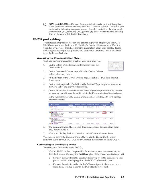
5. On the drivers list, locate the model name of your output device. In the row<br />
for your device, click on the nnKb link in the Communication Sheet column.<br />
In the example below, the Communication sheet link for a 3M-7340 display<br />
has been selected.<br />
6. The Communication Sheet, a .pdf document, opens. You can view, print,<br />
<strong>and</strong>/or download it.<br />
7. Wire your display device as described in its Communication Sheet.<br />
You can also access the Communication Sheets via the Global Configurator<br />
software. Refer to your IPL T PC1 Setup Guide for information on using GC2.3.<br />
Connecting to the display device<br />
To connect the display device to the PC1,<br />
1. Wire an RS-232 cable to the provided four-pin captive screw connector, as<br />
described below. Use only the first three pins of the connector, starting at left.<br />
a. Connect the wire from the display’s Receive port to the connector’s first<br />
pin on the left, which plugs into the PC1’s Tx (Transmit) port.<br />
b. Connect the wire from the display’s Transmit port to the connector’s<br />
second pin, which plugs into the PC1’s Rx (Receive) port.<br />
IPL T PC1 Installation <strong>and</strong> Rear Panel<br />
2-5<br />
PRELIMINARY