Ethernet Configuration and Control, cont'd - Extron Electronics
Ethernet Configuration and Control, cont'd - Extron Electronics
Ethernet Configuration and Control, cont'd - Extron Electronics

Create successful ePaper yourself
Turn your PDF publications into a flip-book with our unique Google optimized e-Paper software.
IP Link Power <strong>Control</strong> Interface<br />
IPL T PC1 <strong>and</strong> IPL T PC1i<br />
68-738-10 Rev. A<br />
06 07
Precautions<br />
Safety Instructions • English<br />
This symbol is intended to alert the user of important operating <strong>and</strong> maintenance<br />
(servicing) instructions in the literature provided with the equipment.<br />
This symbol is intended to alert the user of the presence of uninsulated dangerous<br />
voltage within the product's enclosure that may present a risk of electric shock.<br />
Caution<br />
Read Instructions • Read <strong>and</strong> underst<strong>and</strong> all safety <strong>and</strong> operating instructions before using the<br />
equipment.<br />
Retain Instructions The safety instructions should be kept for future reference.<br />
Follow Warnings Follow all warnings <strong>and</strong> instructions marked on the equipment or in the user<br />
information.<br />
Avoid Attachments Do not use tools or attachments that are not recommended by the equipment<br />
manufacturer because they may be hazardous.<br />
Consignes de Sécurité Français<br />
Ce symbole sert à avertir l’utilisateur que la documentation fournie avec le matériel<br />
contient des instructions importantes concernant l’exploitation et la maintenance<br />
(réparation).<br />
Ce symbole sert à avertir l’utilisateur de la présence dans le boîtier de l’appareil de<br />
tensions dangereuses non isolées posant des risques d’électrocution.<br />
Attention<br />
Lire les instructions Prendre connaissance de toutes les consignes de sécurité et d’exploitation avant<br />
d’utiliser le matériel.<br />
Conserver les instructions Ranger les consignes de sécurité afin de pouvoir les consulter à l’avenir.<br />
Respecter les avertissements Observer tous les avertissements et consignes marqués sur le matériel ou<br />
présentés dans la documentation utilisateur.<br />
Eviter les pièces de fixation Ne pas utiliser de pièces de fixation ni d’outils non recomm<strong>and</strong>és par le<br />
fabricant du matériel car cela risquerait de poser certains dangers.<br />
Sicherheitsanleitungen Deutsch<br />
Dieses Symbol soll dem Benutzer in der im Lieferumfang enthaltenen<br />
Dokumentation besonders wichtige Hinweise zur Bedienung und Wartung<br />
(Inst<strong>and</strong>haltung) geben.<br />
Dieses Symbol soll den Benutzer darauf aufmerksam machen, daß im Inneren des<br />
Gehäuses dieses Produktes gefährliche Spannungen, die nicht isoliert sind und<br />
die einen elektrischen Schock verursachen können, herrschen.<br />
Achtung<br />
Lesen der Anleitungen Bevor Sie das Gerät zum ersten Mal verwenden, sollten Sie alle Sicherheitsund<br />
Bedienungsanleitungen genau durchlesen und verstehen.<br />
Aufbewahren der Anleitungen Die Hinweise zur elektrischen Sicherheit des Produktes sollten Sie<br />
aufbewahren, damit Sie im Bedarfsfall darauf zurückgreifen können.<br />
Befolgen der Warnhinweise Befolgen Sie alle Warnhinweise und Anleitungen auf dem Gerät oder in<br />
der Benutzerdokumentation.<br />
Keine Zusatzgeräte Verwenden Sie keine Werkzeuge oder Zusatzgeräte, die nicht ausdrücklich vom<br />
Hersteller empfohlen wurden, da diese eine Gefahrenquelle darstellen können.<br />
Instrucciones de seguridad Español<br />
Este símbolo se utiliza para advertir al usuario sobre instrucciones importantes de<br />
operación y mantenimiento (o cambio de partes) que se desean destacar en el<br />
contenido de la documentación suministrada con los equipos.<br />
Este símbolo se utiliza para advertir al usuario sobre la presencia de elementos con<br />
voltaje peligroso sin protección aislante, que puedan encontrarse dentro de la caja<br />
o alojamiento del producto, y que puedan representar riesgo de electrocución.<br />
Precaucion<br />
Leer las instrucciones Leer y analizar todas las instrucciones de operación y seguridad, antes de usar<br />
el equipo.<br />
Conservar las instrucciones Conservar las instrucciones de seguridad para futura consulta.<br />
Obedecer las advertencias Todas las advertencias e instrucciones marcadas en el equipo o en la<br />
documentación del usuario, deben ser obedecidas.<br />
Evitar el uso de accesorios No usar herramientas o accesorios que no sean especificamente<br />
recomendados por el fabricante, ya que podrian implicar riesgos.<br />
<br />
<br />
<br />
<br />
<br />
<br />
<br />
<br />
Warning<br />
Power sources This equipment should be operated only from the power source indicated on the product.<br />
This equipment is intended to be used with a main power system with a grounded (neutral)<br />
conductor. The third (grounding) pin is a safety feature, do not attempt to bypass or disable it.<br />
Power disconnection To remove power from the equipment safely, remove all power cords from the rear<br />
of the equipment, or the desktop power module (if detachable), or from the power source receptacle<br />
(wall plug).<br />
Power cord protection Power cords should be routed so that they are not likely to be stepped on or<br />
pinched by items placed upon or against them.<br />
Servicing Refer all servicing to qualified service personnel. There are no user-serviceable parts inside. To<br />
prevent the risk of shock, do not attempt to service this equipment yourself because opening or<br />
removing covers may expose you to dangerous voltage or other hazards.<br />
Slots <strong>and</strong> openings If the equipment has slots or holes in the enclosure, these are provided to prevent<br />
overheating of sensitive components inside. These openings must never be blocked by other objects.<br />
Lithium battery There is a danger of explosion if battery is incorrectly replaced. Replace it only with the<br />
same or equivalent type recommended by the manufacturer. Dispose of used batteries according to the<br />
manufacturer's instructions.<br />
Avertissement<br />
Alimentations Ne faire fonctionner ce matériel qu’avec la source d’alimentation indiquée sur l’appareil.<br />
Ce matériel doit être utilisé avec une alimentation principale comportant un fil de terre (neutre). Le<br />
troisième contact (de mise à la terre) constitue un dispositif de sécurité : n’essayez pas de la<br />
contourner ni de la désactiver.<br />
Déconnexion de l’alimentation Pour mettre le matériel hors tension sans danger, déconnectez tous les<br />
cordons d’alimentation de l’arrière de l’appareil ou du module d’alimentation de bureau (s’il est<br />
amovible) ou encore de la prise secteur.<br />
Protection du cordon d’alimentation Acheminer les cordons d’alimentation de manière à ce que<br />
personne ne risque de marcher dessus et à ce qu’ils ne soient pas écrasés ou pincés par des objets.<br />
Réparation-maintenance Faire exécuter toutes les interventions de réparation-maintenance par un<br />
technicien qualifié. Aucun des éléments internes ne peut être réparé par l’utilisateur. Afin d’éviter tout<br />
danger d’électrocution, l’utilisateur ne doit pas essayer de procéder lui-même à ces opérations car<br />
l’ouverture ou le retrait des couvercles risquent de l’exposer à de hautes tensions et autres dangers.<br />
Fentes et orifices Si le boîtier de l’appareil comporte des fentes ou des orifices, ceux-ci servent à<br />
empêcher les composants internes sensibles de surchauffer. Ces ouvertures ne doivent jamais être<br />
bloquées par des objets.<br />
Lithium Batterie Il a danger d'explosion s'll y a remplacment incorrect de la batterie. Remplacer<br />
uniquement avec une batterie du meme type ou d'un ype equivalent recomm<strong>and</strong>e par le constructeur.<br />
Mettre au reut les batteries usagees conformement aux instructions du fabricant.<br />
Vorsicht<br />
Stromquellen Dieses Gerät sollte nur über die auf dem Produkt angegebene Stromquelle betrieben<br />
werden. Dieses Gerät wurde für eine Verwendung mit einer Hauptstromleitung mit einem geerdeten<br />
(neutralen) Leiter konzipiert. Der dritte Kontakt ist für einen Erdanschluß, und stellt eine<br />
Sicherheitsfunktion dar. Diese sollte nicht umgangen oder außer Betrieb gesetzt werden.<br />
Stromunterbrechung Um das Gerät auf sichere Weise vom Netz zu trennen, sollten Sie alle Netzkabel<br />
aus der Rückseite des Gerätes, aus der externen Stomversorgung (falls dies möglich ist) oder aus der<br />
W<strong>and</strong>steckdose ziehen.<br />
Schutz des Netzkabels Netzkabel sollten stets so verlegt werden, daß sie nicht im Weg liegen und<br />
niem<strong>and</strong> darauf treten kann oder Objekte darauf- oder unmittelbar dagegengestellt werden können.<br />
Wartung Alle Wartungsmaßnahmen sollten nur von qualifiziertem Servicepersonal durchgeführt<br />
werden. Die internen Komponenten des Gerätes sind wartungsfrei. Zur Vermeidung eines<br />
elektrischen Schocks versuchen Sie in keinem Fall, dieses Gerät selbst öffnen, da beim Entfernen der<br />
Abdeckungen die Gefahr eines elektrischen Schlags und/oder <strong>and</strong>ere Gefahren bestehen.<br />
Schlitze und Öffnungen Wenn das Gerät Schlitze oder Löcher im Gehäuse aufweist, dienen diese zur<br />
Vermeidung einer Überhitzung der empfindlichen Teile im Inneren. Diese Öffnungen dürfen niemals<br />
von <strong>and</strong>eren Objekten blockiert werden.<br />
Litium-Batterie Explosionsgefahr, falls die Batterie nicht richtig ersetzt wird. Ersetzen Sie verbrauchte<br />
Batterien nur durch den gleichen oder einen vergleichbaren Batterietyp, der auch vom Hersteller<br />
empfohlen wird. Entsorgen Sie verbrauchte Batterien bitte gemäß den Herstelleranweisungen.<br />
Advertencia<br />
Alimentación eléctrica Este equipo debe conectarse únicamente a la fuente/tipo de alimentación eléctrica<br />
indicada en el mismo. La alimentación eléctrica de este equipo debe provenir de un sistema de<br />
distribución general con conductor neutro a tierra. La tercera pata (puesta a tierra) es una medida de<br />
seguridad, no puentearia ni eliminaria.<br />
Desconexión de alimentación eléctrica Para desconectar con seguridad la acometida de alimentación<br />
eléctrica al equipo, desenchufar todos los cables de alimentación en el panel trasero del equipo, o<br />
desenchufar el módulo de alimentación (si fuera independiente), o desenchufar el cable del<br />
receptáculo de la pared.<br />
Protección del cables de alimentación Los cables de alimentación eléctrica se deben instalar en lugares<br />
donde no sean pisados ni apretados por objetos que se puedan apoyar sobre ellos.<br />
Reparaciones/mantenimiento Solicitar siempre los servicios técnicos de personal calificado. En el interior<br />
no hay partes a las que el usuario deba acceder. Para evitar riesgo de electrocución, no intentar<br />
personalmente la reparación/mantenimiento de este equipo, ya que al abrir o extraer las tapas puede<br />
quedar expuesto a voltajes peligrosos u otros riesgos.<br />
Ranuras y aberturas Si el equipo posee ranuras o orificios en su caja/alojamiento, es para evitar el<br />
sobrecalientamiento de componentes internos sensibles. Estas aberturas nunca se deben obstruir con<br />
otros objetos.<br />
Batería de litio Existe riesgo de explosión si esta batería se coloca en la posición incorrecta. Cambiar esta<br />
batería únicamente con el mismo tipo (o su equivalente) recomendado por el fabricante. Desachar las<br />
baterías usadas siguiendo las instrucciones del fabricante.
FCC Class A Notice<br />
This equipment has been tested <strong>and</strong> found to comply with the limits for a Class A digital<br />
device, pursuant to part 15 of the FCC Rules. These limits are designed to provide reasonable<br />
protection against harmful interference when the equipment is operated in a commercial<br />
environment. This equipment generates, uses <strong>and</strong> can radiate radio frequency energy <strong>and</strong>, if not<br />
installed <strong>and</strong> used in accordance with the instruction manual, may cause harmful interference to<br />
radio communications. Operation of this equipment in a residential area is likely to cause harmful<br />
interference, in which case the user will be required to correct the interference at his own expense.<br />
This unit was tested with shielded cables on the peripheral devices. Shielded cables must<br />
be used with the unit to ensure compliance.<br />
This device complies with Part 15 of the FCC Rules. Operation is subject to the following two<br />
conditions: (1) this device may not cause harmful interference, <strong>and</strong> (2) this device must accept any<br />
interference received, including interference that may cause undesired operation.<br />
PRELIMINARY
PRELIMINARY<br />
Precautions, cont’d<br />
This page was intentionally left blank.
Table of Contents<br />
Chapter 1 Introduction ....................................................................................................... 1-1<br />
About This Manual ............................................................................................................. 1-2<br />
About the IPL T PC1 ............................................................................................................ 1-2<br />
Features .............................................................................................................................. 1-2<br />
Connection diagram .......................................................................................................... 1-3<br />
Chapter 2 Installation <strong>and</strong> Rear Panel ...................................................................... 2-1<br />
Installation Overview ....................................................................................................... 2-2<br />
Mounting the IPL T PC1 Interface ............................................................................... 2-2<br />
Tabletop use ....................................................................................................................... 2-2<br />
Rack mounting ................................................................................................................... 2-2<br />
UL requirements for rack mounting .......................................................................... 2-2<br />
Rack mounting procedure .......................................................................................... 2-3<br />
Under-desk mounting ....................................................................................................... 2-4<br />
Rear Panels <strong>and</strong> Cabling .................................................................................................. 2-4<br />
RS-232 port cabling ............................................................................................................ 2-5<br />
Accessing the Communication Sheet ......................................................................... 2-5<br />
Connecting to the display device ............................................................................... 2-5<br />
Wiring the Local Area Network (LAN) port ...................................................................... 2-6<br />
Wiring for IR control .......................................................................................................... 2-7<br />
Wiring the contact Input port ........................................................................................... 2-8<br />
Connecting the Hardware............................................................................................... 2-8<br />
Chapter 3 Front Panel Features <strong>and</strong> Operation ................................................. 3-1<br />
Front Panel Features ......................................................................................................... 3-2<br />
Setting up the System Using the Front Panel ...................................................... 3-3<br />
Setting up power control .................................................................................................. 3-3<br />
Front panel security lockout (executive mode) ................................................................ 3-3<br />
Resetting ................................................................................................................................. 3-4<br />
Mode 1 (reset firmware) ................................................................................................... 3-4<br />
Mode 2 (enable host port) ................................................................................................ 3-4<br />
Mode 3 (toggle event scripting on <strong>and</strong> off) ..................................................................... 3-5<br />
Mode 4 (reset IP settings) .................................................................................................. 3-5<br />
Mode 5 (complete reset) ................................................................................................... 3-6<br />
Chapter 4 <strong>Ethernet</strong> <strong>Configuration</strong> <strong>and</strong> <strong>Control</strong> ................................................. 4-1<br />
Configuring the Hardware for <strong>Ethernet</strong> <strong>Control</strong> ................................................ 4-2<br />
Setting up <strong>and</strong> configuring the PC1 using ARP ............................................................... 4-2<br />
Setting up <strong>and</strong> configuring the PC1 using a Web browser ............................................. 4-4<br />
Setting up the computer for IP communication ....................................................... 4-4<br />
Configuring the IPL T PC1 using a Web browser....................................................... 4-7<br />
IPL T PC1 • Table of Contents<br />
i<br />
PRELIMINARY
PRELIMINARY<br />
Table of Contents, cont’d<br />
Using the IPL T PC1 Web Pages ..................................................................................... 4-8<br />
Viewing the system status ................................................................................................. 4-9<br />
Using the <strong>Configuration</strong> pages ....................................................................................... 4-10<br />
Specifying system settings ........................................................................................ 4-10<br />
IP settings ............................................................................................................. 4-11<br />
Date <strong>and</strong> time settings ........................................................................................ 4-11<br />
Configuring the RS-232 port <strong>and</strong> the AC receptacle .............................................. 4-12<br />
Contact Input port ............................................................................................... 4-12<br />
RS-232 port........................................................................................................... 4-13<br />
AC receptacle ....................................................................................................... 4-13<br />
Using the IR Drivers screen ....................................................................................... 4-13<br />
Performing a comm<strong>and</strong> ...................................................................................... 4-14<br />
Assigning passwords ................................................................................................. 4-14<br />
Removing passwords ........................................................................................... 4-15<br />
Entering e-mail addresses ......................................................................................... 4-16<br />
Setting up SMTP authentication ......................................................................... 4-17<br />
Upgrading firmware ................................................................................................. 4-18<br />
Downloading the firmware from the Web ........................................................ 4-18<br />
Updating the firmware ....................................................................................... 4-18<br />
Scheduling ................................................................................................................. 4-20<br />
Scheduling output receptacle power ................................................................. 4-20<br />
Scheduling front panel lockout .......................................................................... 4-21<br />
Scheduling by day of the week .......................................................................... 4-22<br />
Changing an individual setting .......................................................................... 4-23<br />
Managing files ................................................................................................................. 4-24<br />
Uploading files to the Web page ............................................................................. 4-24<br />
Adding a directory .................................................................................................... 4-25<br />
Other file management functions ........................................................................... 4-25<br />
Custom Web Pages .............................................................................................4-25<br />
Server side includes (SSIs) ................................................................................................ 4-25<br />
Query strings .................................................................................................................... 4-26<br />
Code example .................................................................................................................. 4-26<br />
URL encoding ................................................................................................................... 4-27<br />
Reserved characters .................................................................................................. 4-28<br />
Unsafe characters ...................................................................................................... 4-28<br />
Accessing <strong>and</strong> Using Telnet (Port 23) ...................................................................... 4-29<br />
Troubleshooting ................................................................................................................ 4-30<br />
Power connections ........................................................................................................... 4-30<br />
Network connections ....................................................................................................... 4-31<br />
Global Configurator Software ................................................................................... 4-32<br />
Chapter 5 SIS Programming <strong>and</strong> <strong>Control</strong> ............................................................ 5-1<br />
Host-to-Interface Communications............................................................................ 5-2<br />
Messages initiated by the IPL T PC1 .................................................................................. 5-2<br />
Password information ....................................................................................................... 5-2<br />
Error responses ................................................................................................................... 5-2<br />
Error response references .................................................................................................. 5-3<br />
ii IPL T PC1 Table of Contents
Using the Comm<strong>and</strong>/Response Table ........................................................................ 5-3<br />
Symbol definitions ............................................................................................................. 5-5<br />
Comm<strong>and</strong>/response table for SIS comm<strong>and</strong>s ................................................................... 5-8<br />
Appendix A Reference Material .................................................................................. A-1<br />
Specifications....................................................................................................................... A-2<br />
Part Numbers <strong>and</strong> Accessories .................................................................................... A-4<br />
Included parts ................................................................................................................... A-4<br />
Optional accessories ......................................................................................................... A-4<br />
Glossary .................................................................................................................................. A-5<br />
All trademarks mentioned in this manual are the properties of their respective owners.<br />
IPL T PC1 Table of Contents<br />
68-738-10 Rev. A<br />
06 07<br />
iii<br />
PRELIMINARY
PRELIMINARY<br />
Table of Contents, cont’d<br />
iv IPL T PC1 Table of Contents<br />
This page was intentionally left blank.
IPL T PC1<br />
1<br />
Chapter One<br />
Introduction<br />
About this Manual<br />
About the IPL T PC1
PRELIMINARY<br />
Introduction<br />
1-2<br />
About this Manual<br />
This manual contains information about the <strong>Extron</strong> IPL T PC1/IPL T PC1i<br />
<strong>Ethernet</strong>-based Power <strong>Control</strong> Interface, including explanations of how to install,<br />
configure, <strong>and</strong> operate it.<br />
About the IPL T PC1<br />
The <strong>Extron</strong> IPL T PC1 <strong>and</strong> IPL T PC1i IP Link ® Power <strong>Control</strong> Interfaces are<br />
<strong>Ethernet</strong>-based power management devices that provide the capability to control<br />
<strong>and</strong> schedule AC power on <strong>and</strong> off. Monitoring of various device conditions is also<br />
available with Global Configurator (GC2.3) software.<br />
The PC1 <strong>and</strong> PC1i ports include a LAN port, a bidirectional RS-232 port, an IR<br />
output port, <strong>and</strong> a contact closure input port, providing integration of power<br />
control, serial device control, IR device control, <strong>and</strong> input sensing in a single device<br />
that can be easily mounted on a rack or behind a display device or kiosk.<br />
The IPL T PC1i is an international version, configured for 220 VAC. Unless<br />
otherwise specified, “IPL T PC1” <strong>and</strong> “PC1” refer to both product versions<br />
throughout this manual.<br />
The PC1 can be used as a st<strong>and</strong>-alone control device or as one of many nodes in a<br />
distributed control system environment.<br />
Features<br />
IPL T PC1 Introduction<br />
Remote powering on <strong>and</strong> off of a device — Centralized management features<br />
such as Telnet allow remote powering on <strong>and</strong> off of a plasma display, camera,<br />
video conferencing equipment, switcher, or other audio/video device. The<br />
Power button on the front panel lets you turn power on <strong>and</strong> off to the<br />
connected device, while an LED to the lower-right of the Power button lights<br />
green to indicate that the device is receiving power.<br />
RS-232 control — The bidirectional serial port on the rear panel, along with an<br />
<strong>Extron</strong> serial driver, enables RS-232 control of an output device.<br />
IR control — An IR port on the rear panel enables unidirectional device control via<br />
an IR emitter, supported by <strong>Extron</strong> IR drivers.<br />
Contact closure input port — This port can detect a closed circuit between an input<br />
<strong>and</strong> ground, <strong>and</strong> trigger an event that has been set up in GC2.3 (e.g., set off an<br />
alarm, turn on a light, <strong>and</strong>/or notify you by e-mail that an event has<br />
occurred).<br />
Industry st<strong>and</strong>ard <strong>Ethernet</strong> protocols — The PC1 uses st<strong>and</strong>ard <strong>Ethernet</strong> <strong>and</strong><br />
TCP/IP communication protocols, including ARP (Address Resolution<br />
Protocol), DHCP (dynamic host configuration protocol), TCP/IP<br />
(Transmission <strong>Control</strong> Protocol/Internet Protocol), Telnet, <strong>and</strong> HTTP<br />
(HyperText Transfer Protocol).<br />
Integral high-performance Web server — The PC1 has a built-in Web server with<br />
memory available for storing device drivers, GlobalViewer, <strong>and</strong> custom user<br />
Web pages.<br />
<strong>Configuration</strong> utility — Global Configurator software, a free, easy to use<br />
Windows ® -based configuration utility, makes product setup simple <strong>and</strong><br />
intuitive; no programming knowledge is required.<br />
E-mail capabilities to enable support — With e-mail notification, technical support<br />
administrators can receive failure <strong>and</strong> service messages through an e-mail<br />
enabled cell phone, PDA, pager, or Internet e-mail account.
Web-based A/V asset management — When used with GlobalViewer software, the<br />
PC1 provides a powerful, flexible way to manage, monitor, <strong>and</strong> control a<br />
projector, flat-panel display, etc., using a st<strong>and</strong>ard <strong>Ethernet</strong> network.<br />
Scheduling of power <strong>and</strong> executive mode — Power to an output device can be<br />
scheduled using the Web pages, SIS comm<strong>and</strong>s, or Global Configurator.<br />
Front panel lockout (executive mode) can also be scheduled by these methods.<br />
Easy configuration <strong>and</strong> control — You can easily control the PC1 using:<br />
The Internet Explorer V5.5 browser<br />
A Web-based interface<br />
DataViewer (or a st<strong>and</strong>ard Telnet client application)<br />
Extensive library of device drivers — Device drivers allow <strong>Extron</strong> products to<br />
control various display <strong>and</strong> source devices, such as projectors, flat-panel<br />
displays, <strong>and</strong> DVD players. <strong>Extron</strong> has produced thous<strong>and</strong>s of fully tested<br />
<strong>and</strong> uniformly modeled RS-232 <strong>and</strong> IR device drivers.<br />
Direct port access — Use existing software programs to control a device that has no<br />
<strong>Ethernet</strong> support. Any existing <strong>Extron</strong> product with a serial control port can<br />
be interfaced with a LAN.<br />
Built-in multi-level security — You can control access to devices attached to the<br />
interface. Two levels of password protection provide appropriate security.<br />
Simultaneous multi-user support — Each IPL T S interface supports multiple<br />
concurrent users, improving system throughput.<br />
Multiple mounting options — The PC1 can be placed on a tabletop, for which four<br />
feet are provided <strong>and</strong> can be attached. Optional hardware for mounting the<br />
unit under a desktop or podium or on a rack shelf is not included, but may be<br />
ordered separately.<br />
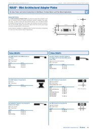
Connection diagram<br />
The following application diagram shows an example of how a device may be<br />
connected to the IPL T PC1 or the IPL T PC1i.<br />
<strong>Extron</strong><br />
IPL T PC1<br />
<strong>Ethernet</strong> <strong>Control</strong><br />
Interface<br />
AC Power<br />
ON<br />
100-120V 50/60Hz<br />
Kiosk<br />
Button<br />
15A MAX POWER OUTPUT 15A MAX<br />
COM<br />
TX RX +5V<br />
INPUT IR<br />
IN S G<br />
RS-232<br />
LAN<br />
Plasma<br />
Display<br />
<strong>Ethernet</strong><br />
DVD<br />
<strong>Extron</strong><br />
IR Emitter<br />
Connection diagram for an IPL T PC1<br />
TCP/IP<br />
Network<br />
IPL T PC1 Introduction<br />
Remote User<br />
<strong>Control</strong> <strong>and</strong><br />
Administrator<br />
Monitoring<br />
1-3<br />
PRELIMINARY
PRELIMINARY<br />
Introduction, cont’d<br />
1-4<br />
IPL T PC1 Introduction<br />
This page was intentionally left blank.
IPL T PC1<br />
2<br />
Chapter Two<br />
Installation <strong>and</strong> Rear Panel<br />
Installation Overview<br />
Mounting the IPL T PC1 Interface<br />
Rear Panels <strong>and</strong> Cabling<br />
Connecting the Hardware
PRELIMINARY<br />
Installation <strong>and</strong> Rear Panel<br />
2-2<br />
Installation Overview<br />
To install <strong>and</strong> set up an IPL T PC1 interface,<br />
1 Disconnect power from the PC1 interface <strong>and</strong> the output device (plasma<br />
display, VCR, projector, etc.).<br />
2<br />
3<br />
4<br />
5<br />
Mount the PC1 interface, if desired. See “Mounting the IPL T PC1 Interface,”<br />
below.<br />
Plug the PC1 power cord into an AC wall outlet.<br />
Connect a LAN <strong>Ethernet</strong> cable from your computer to the RJ-45 port on the<br />
PC1 rear panel to establish a link to the network.<br />
Set up an IP address for the PC1. (See chapter 4, “<strong>Ethernet</strong> <strong>Configuration</strong> <strong>and</strong><br />
<strong>Control</strong>” or chapter 5,” SIS Programming <strong>and</strong> <strong>Control</strong>.”)<br />
6 Plug an output device into the output power receptacle on the PC1 rear panel.<br />
7 If desired, connect the output device to the serial COM port.<br />
8<br />
9<br />
If desired, connect a contact closure device to the Input port.<br />
If desired, connect an IR emitter to the IR port.<br />
10 Press the front panel button to power on the receptacle.<br />
11 Power on the output device.<br />
12 Configure the PC1 interface using Global Configurator (provided on the<br />
included software CD-ROM) or the embedded Web pages.<br />
Mounting the IPL T PC1 Interface<br />
The IPL T PC1 can be set on a table, mounted on a rack shelf, or mounted under<br />
furniture such as a desk, podium, or tabletop.<br />
Tabletop use<br />
Four self-adhesive rubber feet are included with the PC1. For tabletop use, attach<br />
one foot at each corner of the bottom side of the unit, <strong>and</strong> place the PC1 in the<br />
desired location.<br />
Rack mounting<br />
Rack mount the interface, if desired, using one of the optional 19" wide rack<br />
shelves:<br />
RSB 129 — 9.5" deep basic rack shelf, part #60-604-01<br />
RSU 129 — 9.5" deep Universal rack shelf kit, part #60-190-01<br />
RSB 126 — 6" deep basic rack shelf, part #60-604-10<br />
RSU 126 — 6" deep Universal rack shelf kit, part #60-190-10<br />
UL requirements for rack mounting<br />
The following Underwriters Laboratories (UL) requirements pertain to the<br />
installation of the interface into a rack.<br />
Elevated operating ambient temperature — If the equipment is installed in a<br />
closed or multi-unit rack assembly, the operating ambient temperature of the<br />
rack environment may be greater than room ambient. Therefore, consider<br />
installing the equipment in an environment compatible with the maximum<br />
ambient temperature (Tma) specified by the manufacturer.<br />
IPL T PC1 Installation <strong>and</strong> Rear Panel
Reduced air flow — Installation of the equipment in a rack should be such<br />
that the amount of air flow required for safe operation of the equipment is not<br />
compromised.<br />
Mechanical loading — Mounting of the equipment in the rack should be such<br />
that a hazardous condition is not created due to uneven mechanical loading.<br />
Circuit overloading — Consideration should be given to the connection of the<br />
equipment to the supply circuit <strong>and</strong> the effect that overloading of the circuits<br />
might have on overcurrent protection <strong>and</strong> supply wiring. Appropriate<br />
consideration of equipment nameplate ratings should be used when<br />
addressing this concern.<br />
Reliable earthing (grounding) — Reliable earthing of rack-mounted<br />
equipment should be maintained. Particular attention should be given to<br />
supply connections other than direct connections to the branch circuit (e.g.<br />
use of power strips.<br />
Rack mounting procedure<br />
To mount the PC1 on a rack shelf,<br />
1. If rubber feet have been installed on the bottom of the unit, remove them.<br />
2. Mount the PC1 on the rack shelf, using two 4-40 x 3/16" screws in opposite<br />
(diagonal) corners of the unit to secure it to the shelf.<br />
3. Attach a blank panel or other unit(s) to the rack shelf.<br />
RSU 129<br />
1U Universal Rack Shelf<br />
Both front false faceplates<br />
use 2 screws.<br />
Use 2 mounting holes on<br />
opposite corners.<br />
1/2 Rack Width Front False<br />
Faceplate<br />
1/4 Rack Width Front False<br />
Faceplate<br />
(2) 4-40 x 3/16"<br />
Screws<br />
Mounting the IPL T PC1 on an RSU 129 Universal rack shelf<br />
4. Insert the shelf into the rack, aligning the holes in the shelf with those in the<br />
rack.<br />
5. Secure the shelf to the rack using the supplied machine screws. This shelf can<br />
be mounted in the front or in the rear of the rack.<br />
IPL T PC1 Installation <strong>and</strong> Rear Panel<br />
2-3<br />
PRELIMINARY
PRELIMINARY<br />
Installation <strong>and</strong> Rear Panel, cont’d<br />
2-4<br />
Under-desk mounting<br />
The PC1 can also be mounted under furniture, such as a table or podium surface,<br />
using the optional under-desk mounting kit MBU 125 (part #70-077-01).<br />
1. If rubber feet were previously installed on the bottom of the unit, remove<br />
them.<br />
2. Attach the mounting brackets to<br />
the unit with the provided<br />
machine screws.<br />
3. Insert #8 wood screws into the<br />
four pilot holes. Tighten each<br />
screw into the mounting surface<br />
until slightly less than ¼" of the<br />
screw protrudes.<br />
4. Align the mounting screws with<br />
the slots in the brackets, <strong>and</strong><br />
place the PC1 against the surface<br />
with the screws through the<br />
bracket slots.<br />
5. Slide the unit slightly forward or back, then tighten all four screws to secure it<br />
in place.<br />
Rear Panels <strong>and</strong> Cabling<br />
1 2 3<br />
100-120VAC 50/60Hz<br />
12A MAX<br />
MAC ADDRESS<br />
POWER OUTPUT 12A MAX<br />
IPL T PC1 Installation <strong>and</strong> Rear Panel<br />
COM<br />
TX RX<br />
INPUT IR<br />
+5V<br />
IN S G<br />
7 6 5<br />
IPL T PC1 rear panel (120 VAC)<br />
1 2 3<br />
200-240VAC 50/60Hz<br />
10A MAX<br />
MAC ADDRESS<br />
POWER OUTPUT 10A MAX<br />
COM<br />
TX RX<br />
INPUT IR<br />
+5V<br />
IN S G<br />
7 6 5<br />
® US<br />
LISTED 17TT<br />
AUDIO/VIDEO<br />
APARATUS<br />
LAN<br />
® US<br />
LISTED 17TT<br />
AUDIO/VIDEO<br />
APARATUS<br />
LAN<br />
IPL T PC1i rear panel (220 VAC)<br />
1<br />
2<br />
4<br />
4<br />
Power connector — Connect a power cord from a wall outlet to this male IEC<br />
power receptacle.<br />
UID # label — Contains the unique User ID number (MAC address) of the<br />
unit (for example, 00-05-A6-00-00-01).
3<br />
COM port (RS-232) — Connect the output device serial port to this captive<br />
screw connector to enable bidirectional RS-232 device control. This serial port<br />
contains the following four pins, in order from left to right on the rear panel:<br />
Transmission (TX), receiving (RX), ground ( ), <strong>and</strong> +5 V (to tie h<strong>and</strong>-shaking<br />
lines on the controlled device if needed).<br />
RS-232 port cabling<br />
To connect an output device, such as a plasma display or projector, to the PC1’s<br />
RS-232 connector, see the <strong>Extron</strong> IP Link Device Interface Communication Sheet for<br />
your display device. This sheet contains information about your display device,<br />
including connector pin assignments <strong>and</strong> connection diagrams, <strong>and</strong> is available<br />
from the <strong>Extron</strong> Web site.<br />
Accessing the Communication Sheet<br />
To obtain the Communication Sheet for your output device,<br />
1. On the <strong>Extron</strong> Web site (www.extron.com), click the<br />
Download tab.<br />
2. On the Download Center page, click the Device Drivers<br />
button (shown at right).<br />
3. At the bottom of the Device Drivers page, select IPL T PC1 from the pulldown<br />
menu.<br />
4. On the next page, select Serial from the Protocol Type drop-down menu to<br />
display a list of the <strong>Extron</strong> serial drivers.<br />
5. On the drivers list, locate the model name of your output device. In the row<br />
for your device, click on the nnKb link in the Communication Sheet column.<br />
In the example below, the Communication sheet link for a 3M-7340 display<br />
has been selected.<br />
6. The Communication Sheet, a .pdf document, opens. You can view, print,<br />
<strong>and</strong>/or download it.<br />
7. Wire your display device as described in its Communication Sheet.<br />
You can also access the Communication Sheets via the Global Configurator<br />
software. Refer to your IPL T PC1 Setup Guide for information on using GC2.3.<br />
Connecting to the display device<br />
To connect the display device to the PC1,<br />
1. Wire an RS-232 cable to the provided four-pin captive screw connector, as<br />
described below. Use only the first three pins of the connector, starting at left.<br />
a. Connect the wire from the display’s Receive port to the connector’s first<br />
pin on the left, which plugs into the PC1’s Tx (Transmit) port.<br />
b. Connect the wire from the display’s Transmit port to the connector’s<br />
second pin, which plugs into the PC1’s Rx (Receive) port.<br />
IPL T PC1 Installation <strong>and</strong> Rear Panel<br />
2-5<br />
PRELIMINARY
PRELIMINARY<br />
Installation <strong>and</strong> Rear Panel, cont’d<br />
2-6<br />
c. Connect the ground wire from the display to the connector’s third pin,<br />
which plugs into the PC1’s ground ( ) port.<br />
RS-232<br />
Tx Rx +5V<br />
IPL T PC1<br />
Rear Panel<br />
RS-232 Port<br />
Ground ( )<br />
Receive (Rx)<br />
Transmit (Tx)<br />
IPL T PC1 Installation <strong>and</strong> Rear Panel<br />
Bidirectional<br />
Ground ( )<br />
Receive (Rx)<br />
Transmit (Tx)<br />
Display<br />
Device<br />
Connecting an output device to the RS-232 port<br />
d. Connect h<strong>and</strong>-shaking wires to the +5V port if needed.<br />
2. Plug the cable into the RS-232 receptacle on the PC1 rear panel.<br />
4<br />
The RS-232 port is by default a control port. If you want to use it to configure<br />
the PC1, you must perform a mode 2 reset. Refer to “Resetting,” in chapter 3,<br />
“Front Panel Features <strong>and</strong> Operation,” for this procedure.<br />
LAN connector <strong>and</strong> LEDs — An <strong>Ethernet</strong> connection can be used on an<br />
ongoing basis to monitor <strong>and</strong> control the PC1 (<strong>and</strong> the device connected to it).<br />
RJ-45 port — Plug a patch cable into this RJ-45 female<br />
socket, <strong>and</strong> connect the other end to a network<br />
switch, hub, router, or PC.<br />
Link LED — This green LED lights to indicate a good<br />
network connection.<br />
Activity LED — This yellow LED blinks to indicate<br />
network activity.<br />
Wiring the Local Area Network (LAN) port<br />
• For 10Base-T (10 Mbps) networks, use a Category 3 or better cable.<br />
For 100Base-T (100 Mbps) networks, use a Category 5 cable.<br />
Use a straight-through cable to connect to a switch, hub, or router.<br />
Use a crossover cable to connect directly to a computer. Wire the<br />
connector as shown in the tables on the next page.<br />
LAN<br />
Activity<br />
LED<br />
RJ-45<br />
Port<br />
Link<br />
LED
Side View<br />
Pins:<br />
12345678<br />
Insert<br />
Twisted<br />
Pair Wires<br />
RJ-45 Connector<br />
RJ-45 connector wiring<br />
5<br />
Wiring for IR control<br />
Straight-through Cable<br />
(for connection to a switch, hub, or router)<br />
End 1 End 2<br />
Pin Wire Color Pin Wire Color<br />
1 white-orange 1 white-orange<br />
2 orange 2 orange<br />
3 white-green 3 white-green<br />
4 blue 4 blue<br />
5 white-blue 5 white-blue<br />
6 green 6 green<br />
7 white-brown 7 white-brown<br />
8 brown 8 brown<br />
Crossover Cable<br />
(for direct connection to a PC)<br />
End 1 End 2<br />
Pin Wire Color Pin Wire Color<br />
1 white-orange 1 white-green<br />
2 orange 2 green<br />
3 white-green 3 white-orange<br />
4 blue 4 blue<br />
5 white-blue 5 white-blue<br />
6 green 6 orange<br />
7 white-brown 7 white-brown<br />
8 brown 8 brown<br />
IR port — Connect an IR Emitter to pins 3 (S, for signal) <strong>and</strong> 4 (G, for<br />
ground) of this shared captive screw connector to enable infrared remote<br />
control of the output device. The PC1 provides enough current to power one<br />
IR Emitter up to 4000 feet, or a maximum of four Emitters in parallel up to 100<br />
feet each. To enable IR control, load an <strong>Extron</strong> IR driver to the PC1for the<br />
output device, using Global Configurator, the PC1 Web pages, or IR Learning.<br />
If you intend to control the display device via infrared (IR) comm<strong>and</strong>s from<br />
the PC1, you can connect an <strong>Extron</strong> IR Emitter to the IR Signal <strong>and</strong> Ground<br />
pins (pins 3 <strong>and</strong> 4) of the shared captive screw connector. The PC1 provides<br />
enough current to power one IR Emitter up to 4000 feet, or up to four Emitters<br />
for 100 feet each. See the wiring illustration below.<br />
In S G<br />
IPL T PC1 Shared IR<br />
<strong>and</strong> Input Connector<br />
Modulated IR<br />
Ground<br />
4000 feet (1574.8 m) maximum<br />
The PC1 can power a single IR Emitter<br />
up to 4000 feet, or four emitters wired<br />
in parallel up to 100 feet each.<br />
Wiring for IR control via an IR Emitter<br />
E<br />
D<br />
White striped wire only<br />
IR<br />
Emitter<br />
Place the head of the IR Emitter<br />
over or directly adjacent to the<br />
controlled device’s IR receiver.<br />
IPL T PC1 Installation <strong>and</strong> Rear Panel<br />
2-7<br />
PRELIMINARY
PRELIMINARY<br />
Installation <strong>and</strong> Rear Panel, cont’d<br />
2-8<br />
6<br />
Input contact closure port — Connect a contact closure device to pins 1 (IN,<br />
for input) <strong>and</strong> 2 ( , for ground) of this shared captive screw connector to<br />
enable the PC1 to detect a closed circuit between an input <strong>and</strong> ground <strong>and</strong> to<br />
trigger an event.<br />
For example, if a button were pressed or motion were detected by a sensor,<br />
the input would short to ground, which would cause an event such as a bell<br />
ringing, a light turning on, <strong>and</strong>/or an e-mail notification that an event has<br />
occurred.<br />
Wiring the contact Input port<br />
7<br />
The IPL T PC1 contact closure Input port can be connected to any device<br />
providing a closure to ground (closed = logic 1 <strong>and</strong> open = logic 0). The<br />
contact Input is connected to 5VDC via a 1k ohm pull-up resistor <strong>and</strong> must be<br />
wired with a ground. This allows the input to be tied to a device such as a<br />
motion detector, alarm, photo eye, etc. You can define what this input will<br />
trigger via GC2.3.<br />
1. Connect one end of the input cable to a<br />
3.5 mm, 5-pole captive screw connector,<br />
wired appropriately, <strong>and</strong> plug it into pins 1<br />
<strong>and</strong> 2 of the shared input/IR port connector<br />
on the rear panel.<br />
2. Connect the other end of the input cable to<br />
the input device that will provide a<br />
triggering signal. (See the diagram at right.)<br />
Output power receptacle — Connect the power cord from an output device<br />
to this three-prong female Edison (IPL T PC1) or IEC (IPL T PC1i) power<br />
output receptacle.<br />
Connecting the Hardware<br />
Connect the cables to the rear panel as follows:<br />
1. Plug an IEC power cord into a wall outlet <strong>and</strong> into the 3-prong male power<br />
connector on the PC1 rear panel. The green Power LED lights <strong>and</strong> remain lit.<br />
2. Plug the <strong>Ethernet</strong> cable from the network into the LAN port on the rear panel.<br />
The Link LED lights green.<br />
3. Plug the power cord of the output device to be controlled into the output<br />
receptacle on the PCI rear panel.<br />
4. If desired, connect the output device to the RS-232 COM port.<br />
5. If desired, connect an IR emitter to the IR port to control an output device.<br />
6. If desired, connect a contact switch to the contact input port.<br />
IPL T PC1 Installation <strong>and</strong> Rear Panel<br />
INPUT IR<br />
IN S G<br />
Momentary<br />
Switch
IPL T PC1<br />
3<br />
Chapter Three<br />
Front Panel Features <strong>and</strong> Operation<br />
Front Panel Features<br />
Setting up the System Using the Front Panel<br />
Resetting
PRELIMINARY<br />
Front Panel Features <strong>and</strong> Operation<br />
3-2<br />
The PC1 can be set up <strong>and</strong> operated by using<br />
The front panel controls<br />
A computer or other device using an <strong>Ethernet</strong> connection <strong>and</strong> IP protocol<br />
(Telnet or a Web browser).<br />
With a network connection, you can adjust settings using both SIS comm<strong>and</strong>s <strong>and</strong><br />
PC1’s embedded Web pages. For details on setup <strong>and</strong> control via the Web pages,<br />
see chapter 4, “<strong>Ethernet</strong> <strong>Configuration</strong> <strong>and</strong> <strong>Control</strong>.” For information on setup <strong>and</strong><br />
control via SIS comm<strong>and</strong>s, see chapter 5, “SIS Programming <strong>and</strong> <strong>Control</strong>.”<br />
Front Panel Features<br />
8<br />
IPL T PC1<br />
R<br />
7<br />
1 2 3<br />
POWER<br />
IPL T PC1 Front Panel Features <strong>and</strong> Operation<br />
TX<br />
RX<br />
6 5<br />
INPUT<br />
IR<br />
100<br />
LINK<br />
ACT<br />
IPL T PC1 <strong>and</strong> IPL T PC1i front panel<br />
1<br />
2<br />
3<br />
4<br />
5<br />
6<br />
7<br />
8<br />
Power button — Press this button to switch power on <strong>and</strong> off to the output<br />
receptacle on the rear panel.<br />
Tx <strong>and</strong> Rx LEDs — The Tx (transmit) LED lights green when RS-232 data is<br />
being transmitted. The Rx LED lights green when RS-232 data is being<br />
received.<br />
Input LED — Lights green when the Input contact closure port is activated<br />
(shorted).<br />
LAN status LEDs — These three LEDs show the status of the <strong>Ethernet</strong><br />
connection as follows:<br />
100 (green) — When lit, indicates a 100 Mbs connection speed.<br />
Otherwise, the connection speed is 10 Mbs.<br />
Link (green) — Indicates that the interface has an active network<br />
connection.<br />
Act (Activity) (yellow) — Blinks while data is being sent or received.<br />
IR LED — Lights green when IR data is being transmitted.<br />
Receptacle power LED — Indicates that power is being supplied to the rear<br />
panel receptacle <strong>and</strong>, therefore, to the attached output device.<br />
Reset button (recessed) — Use the tip of a small Phillips screwdriver or an<br />
<strong>Extron</strong> Tweeker to press this recessed button to reset the unit in one of five<br />
reset modes. See “Resetting,” later in this chapter, for details on reset modes<br />
<strong>and</strong> on using this Reset button.<br />
Power LED — When this green LED is lit, the PC1/PC1i interface is receiving<br />
power <strong>and</strong> is running.<br />
When the unit is being reset from the front panel, this LED blinks the<br />
appropriate number of times to indicate the reset mode the PC1 has entered.<br />
(See “Resetting,” later in this chapter.)<br />
4
Setting Up the System Using the Front Panel<br />
The following system setup procedures can be performed using the front panel,<br />
Global Configurator, the embedded Web pages, or SIS comm<strong>and</strong>s.<br />
This section discusses the front panel procedures. For information on using the<br />
Web to set up, see chapter 4, “<strong>Ethernet</strong> <strong>Configuration</strong> <strong>and</strong> <strong>Control</strong>.” For the<br />
equivalent SIS comm<strong>and</strong>s, see chapter 5, “SIS Programming <strong>and</strong> <strong>Control</strong>.” For<br />
information on setting up using Global Configurator, see the IPL T PC1 Setup Guide.<br />
The PC1 takes approximately 2 minutes to store settings made via the front<br />
panel, SIS comm<strong>and</strong>s, or the Web pages into its memory. If you disconnect<br />
power from the PC1 less than 2 minutes after entering a setting, your entry<br />
may be lost.<br />
Setting up power control<br />
To set up control of power to the output device plugged into the PC1 output power<br />
receptacle,<br />
1. On the PC1 front panel, press <strong>and</strong> release<br />
the receptacle Power button.<br />
The green receptacle Power LED at the right<br />
of the button lights <strong>and</strong> remains lit while<br />
the receptacle is powered on. It turns off<br />
when the receptacle is powered off.<br />
2. Power on the device, using its own power<br />
switch.<br />
If power is removed from the PC1, the power state of the output receptacle is<br />
preserved in flash memory; for example, if the receptacle was powered on when<br />
the PC1 was disconnected, it is powered on when the PC1 receives power again.<br />
This enables the receptacle configuration to be easily restored if a power loss<br />
occurs.<br />
CAUTION<br />
Receptacle<br />
Power Button<br />
POWER<br />
I<br />
Some devices, such as projectors, need a cool-down period to power off<br />
safely. Use RS-232 or IR comm<strong>and</strong>s to power these devices.<br />
Front panel security lockout (executive mode)<br />
When the PC1 is in executive mode, it does not accept comm<strong>and</strong>s from the front<br />
panel. If any button is pressed while the unit is in executive mode, the Power LED<br />
flashes three times, indicating that input from the front panel is not being accepted.<br />
To enter or exit executive mode, press <strong>and</strong> hold the receptacle Power button for<br />
3 seconds. The Power LED flashes 3 times to indicate that the executive mode has<br />
been switched.<br />
If power to the PC1 is recycled while the unit is in executive mode, the PC1<br />
remains in executive mode.<br />
The Reset button is always functional. It is recessed to avoid it being pressed<br />
accidentally.<br />
IPL T PC1 Front Panel Features <strong>and</strong> Operation<br />
Receptacle<br />
Power LED<br />
3-3<br />
PRELIMINARY
PRELIMINARY<br />
Front Panel Features <strong>and</strong> Operation, cont’d<br />
3-4<br />
Resetting There are five ways to reset the PC1 unit (reset modes). Reset the unit by pressing<br />
the Reset button on the front panel. This button is recessed, <strong>and</strong> can be accessed<br />
with an <strong>Extron</strong> Tweeker or other small Phillips screwdriver.<br />
CAUTION<br />
CAUTION<br />
IPL T PC1<br />
R<br />
IPL T PC1 Front Panel Features <strong>and</strong> Operation<br />
POWER<br />
Review the reset modes carefully. Use of the wrong reset mode may cause<br />
unintended loss of flash memory programming or a unit reboot.<br />
The reset modes described on the following pages break all TCP/IP<br />
connections by closing all sockets to the unit.<br />
TX<br />
RX<br />
Recessed Reset Button<br />
Use tip of Philips head<br />
on Tweeker to activate.<br />
Reset button<br />
I<br />
INPUT<br />
IR<br />
100<br />
LINK<br />
ACT<br />
Mode 1 (reset firmware)<br />
If the Reset button is continually held in, the Power LED pulses (blinks) every<br />
3 seconds, <strong>and</strong> with each pulse, the PC1 goes into a different reset mode. For<br />
mode 5, the LED blinks three times, indicating that it is the last mode.<br />
The reset modes are separate functions, not a progression from mode 1 to<br />
mode 5.<br />
Activation — Hold in the Reset button while applying power to the unit.<br />
Result — Returns the unit to the default base firmware that was shipped with the<br />
PC1 from the factory. Event scripting does not start when the unit is powered<br />
on in this mode.<br />
Purpose <strong>and</strong> notes — Use mode 1 to remove a version of firmware if<br />
incompatibility issues arise. All user files <strong>and</strong> settings are maintained. User<br />
Web pages may not work correctly if you are using an earlier firmware<br />
version.<br />
Mode 2 (enable host port)<br />
After a mode 1 reset, the factory-installed firmware version remains in effect<br />
only until the unit is powered off. After a power cycle, the PC1 returns to the<br />
firmware that was installed prior to the mode 1 reset.<br />
Activation — To enter mode 2 you use both the PC1 front panel <strong>and</strong> your<br />
computer, as follows:<br />
1. On the computer, open a comm<strong>and</strong> interface, such as DataViewer.<br />
2. Momentarily (for less than 1 second) press the Reset button.<br />
3. Within 2 seconds of the momentary press, enter +++ on the computer<br />
keyboard.
Result — The RS-232 port is converted to a host port, which allows the use of SIS<br />
comm<strong>and</strong>s <strong>and</strong> host responses.<br />
No LEDs blink to indicate the mode switch. If the switch to mode 2 is<br />
successful <strong>and</strong> serial port communication is enabled, the interface screen<br />
displays one of the following the copyright messages:<br />
(c) Copyright 2007, <strong>Extron</strong> <strong>Electronics</strong>, IPL T PC1, Vx.xx, 60-544-xx<br />
(c) Copyright 2007, <strong>Extron</strong> <strong>Electronics</strong>, IPL T PC1i Vx.xx, 60-544-xx<br />
Purpose <strong>and</strong> notes — By default, the RS-232 is a device control port. In mode 2,<br />
the serial port is able to receive SIS comm<strong>and</strong>s.<br />
If you do not enter the three plus (+) signs within 2 seconds of the momentary<br />
press of the Reset button, the RS-232 port reverts to a device control port.<br />
Mode 3 (toggle event scripting on <strong>and</strong> off)<br />
Activation — Hold the Reset button in until the Power LED blinks one time (about<br />
3 seconds). Release it, then immediately press it again momentarily (for less<br />
than 1 second).<br />
Nothing happens if the momentary press does not occur within 1 second.<br />
Result — Turns events on or off, depending on their current state. During<br />
resetting, the reset LED flashes:<br />
Two times if events are starting<br />
Three times if events are stopping<br />
Purpose <strong>and</strong> notes — This mode is used for troubleshooting.<br />
Mode 4 (reset IP settings)<br />
Activation — Hold the Reset button in until the Power LED blinks two times<br />
(about 6 seconds). Release it, then immediately press it again momentarily<br />
(for less than 1 second). The Power LED blinks four times in quick<br />
succession, confirming a mode 4 reset.<br />
Nothing happens if the momentary press does not occur within 1 second.<br />
Result — Reset mode 4 does the following:<br />
Enables ARP program capability.<br />
Sets IP address back to factory IP settings.<br />
Sets Subnet address back to factory default.<br />
Sets Gateway address back to factory default.<br />
Sets port mapping back to factory default.<br />
Turns DHCP off.<br />
Turns events off.<br />
Purpose <strong>and</strong> notes — Mode 4 enables you to set IP address information using ARP<br />
<strong>and</strong> the MAC address without affecting any files on the unit.<br />
IPL T PC1 Front Panel Features <strong>and</strong> Operation<br />
3-5<br />
PRELIMINARY
PRELIMINARY<br />
Front Panel Features <strong>and</strong> Operation, cont’d<br />
3-6<br />
Mode 5 (complete reset)<br />
Activation — Hold in the Reset button until the Power LED blinks three times<br />
(about 9 seconds). Release it, then immediately press it again momentarily<br />
(for less than 1 second). The power LED blinks four times in quick<br />
succession, confirming a mode 5 reset.<br />
IPL T PC1 Front Panel Features <strong>and</strong> Operation<br />
Nothing happens if the momentary press does not occur within 1 second.<br />
Result — Performs a complete reset to factory defaults, excluding any firmware<br />
upgrades that have been uploaded. The unit will continue to function on the<br />
firmware version that was most recently uploaded.<br />
Purpose <strong>and</strong> notes — Mode 5 is useful if you want to start over with control<br />
software configuration <strong>and</strong> to replace events.
IPL T PC1<br />
4<br />
Chapter Four<br />
<strong>Ethernet</strong> <strong>Configuration</strong> <strong>and</strong> <strong>Control</strong><br />
Configuring the Hardware for <strong>Ethernet</strong> <strong>Control</strong><br />
Using the IPL T PC1 Web Pages<br />
Custom Web Pages<br />
Accessing <strong>and</strong> Using Telnet (Port 23)<br />
Troubleshooting<br />
Global Configurator Software
PRELIMINARY<br />
<strong>Ethernet</strong> <strong>Configuration</strong> <strong>and</strong> <strong>Control</strong><br />
4-2<br />
The IPL T PC1 must be configured before use in order for it to control other devices.<br />
In addition to using the button on the PC1 front panel, you can configure <strong>and</strong><br />
control the PC1 via any computer attached to a LAN.<br />
The default PC1 embedded Web pages provide a means of setting up, adjusting,<br />
<strong>and</strong> controlling via a Web browser from any type of network-enabled computer.<br />
An alternative way to control <strong>and</strong> configure the PC1 from your computer is by<br />
using Simple Instruction Set (SIS) comm<strong>and</strong>s via Telnet. SIS comm<strong>and</strong>s are<br />
discussed in detail in chapter 5, “SIS Programming <strong>and</strong> <strong>Control</strong>.”<br />
Global Configurator (GC2.3) software enables you to configure <strong>and</strong> control the<br />
PC1 as well as set up output device monitoring <strong>and</strong> scheduling. Refer to the<br />
IPL T PC1 Setup Guide, provided with your PC1.<br />
Configuring the Hardware for <strong>Ethernet</strong> <strong>Control</strong><br />
To enable <strong>Ethernet</strong> control, both the PC <strong>and</strong> the PC1 must be configured correctly.<br />
The PC must be network-capable with the proper protocols, <strong>and</strong> the PC1 must be<br />
set up so it can be connected to a LAN (local area network). Please note that some<br />
settings can be configured only via Internet protocol.<br />
For your PC to communicate with the PC1 via <strong>Ethernet</strong>, it must have a Windowsbased<br />
(Windows NT, 2000, XP, or higher) operating system <strong>and</strong> be equipped with<br />
an network interface card. To allow your PC to work with <strong>Extron</strong>’s <strong>Ethernet</strong>controlled<br />
products, the TCP/IP protocol must be installed <strong>and</strong> properly<br />
configured.<br />
Setting up <strong>and</strong> configuring the PC1 using ARP<br />
The Address Resolution Protocol (ARP) comm<strong>and</strong> provides a quick way to set up<br />
an IP address for the PC1, using your PC. The ARP comm<strong>and</strong>s tell your computer<br />
to associate the PC1’s Media Access <strong>Control</strong> (MAC) address with an IP address that<br />
you assign.<br />
1. Obtain a valid IP address for your PC1 from your network administrator.<br />
2. Obtain the PC1’s MAC address (UID#) from the label on the PC1’s rear panel.<br />
The MAC address should have the following format:<br />
00-05-A6-nn-nn-nn<br />
3. If the PC1 has never been configured <strong>and</strong> is still set for factory defaults, skip<br />
to step 4. If not, perform a mode 4 system reset to restore the factory-set<br />
values. (See chapter 3, “Front Panel Features <strong>and</strong> Operations,”“Resetting”<br />
section, for the resetting procedure.)<br />
CAUTION<br />
IPL T PC1 <strong>Ethernet</strong> <strong>Configuration</strong> <strong>and</strong> <strong>Control</strong><br />
The PC1 must be configured with the factory default IP address<br />
(192.168.254.254) before you execute the ARP comm<strong>and</strong>, as described<br />
below.<br />
4. At the PC, access the MS-DOS comm<strong>and</strong> prompt as follows:<br />
a. From your Windows desktop Start menu, select Run... .<br />
b. On the Run window, enter cmd. The MS DOS comm<strong>and</strong> window opens.<br />
5. At the DOS prompt enter arp -s, the desired new IP address for the PC1, a<br />
space, <strong>and</strong> finally the PC1’s MAC address (taken from the label on the rear<br />
panel). For example:<br />
arp -s 10.13.197.57 00-05-A6-01-33-0D<br />
A space must follow arp (i.e., precede the hyphen [-].)
ARP-S comm<strong>and</strong> screen<br />
6. Execute a ping comm<strong>and</strong> by entering “ping,” followed by the new IP address,<br />
at the comm<strong>and</strong> prompt.<br />
Example:<br />
Ping is a utility or diagnostic tool that tests network connections. It is used to<br />
determine if the host has an operating connection <strong>and</strong> is able to exchange<br />
information with another host.<br />
ping 10.13.197.57<br />
The response should be the PC1’s new IP address, as shown below.<br />
Ping comm<strong>and</strong> on Comm<strong>and</strong> Prompt screen<br />
7. After verifying that the IP address change was successful, issue the arp -d<br />
comm<strong>and</strong> at the DOS prompt to remove the address from the computer’s<br />
ARP table. For example:<br />
arp -d 10.13.197.57<br />
A space must follow arp (i.e., precede the hyphen [-].<br />
IPL T PC1 <strong>Ethernet</strong> <strong>Configuration</strong> <strong>and</strong> <strong>Control</strong><br />
4-3<br />
PRELIMINARY
PRELIMINARY<br />
<strong>Ethernet</strong> <strong>Configuration</strong> <strong>and</strong> <strong>Control</strong>, cont’d<br />
4-4<br />
Setting up <strong>and</strong> configuring the PC1 using a Web browser<br />
To set up the PC1 for <strong>Ethernet</strong> communication using a Web browser, you must<br />
temporarily configure the PC to communicate with the interface. Then you can<br />
change the PC1’s default settings (IP address, subnet mask, <strong>and</strong> [optionally]<br />
administrator name <strong>and</strong> password) in order to use the unit on an intranet (LAN) or<br />
on the Internet (WAN). After you have set up the PC1 for network communication,<br />
you can reset the PC to its original network configuration.<br />
IPL T PC1’s LAN port defaults:<br />
PC1’s IP address: 192.168.254.254<br />
Gateway’s IP address: 0.0.0.0<br />
Subnet mask: 255.255.0.0<br />
DHCP: Off<br />
Link speed <strong>and</strong> duplex level: Auto detected<br />
If you use an existing <strong>Ethernet</strong> LAN intranet, your network administrator can<br />
provide you with a unique IP address for the PC1 or confirm whether you need to<br />
set up the PC1 for DHCP (Dynamic Host <strong>Configuration</strong> protocol) to have an<br />
address assigned automatically.<br />
Setting up the computer for IP communication<br />
Follow these steps to set up communication between your computer <strong>and</strong> the PC1<br />
using Windows 2000 or Windows XP.<br />
1. Open the Network Connections page as follows:<br />
Windows 2000:<br />
a. Locate <strong>and</strong> right-click My Network<br />
Places on the Windows desktop.<br />
b. Select Properties.<br />
or<br />
a. Click the Start menu, <strong>and</strong> select Settings<br />
(if necessary).<br />
b. From the Start menu, select <strong>Control</strong> Panel.<br />
c. On the <strong>Control</strong> Panel window, double-click Network Connections, then<br />
Dial-up Connections (if necessary).<br />
<strong>Control</strong> Panel window for Windows 2000<br />
Windows XP:<br />
a. From the Start menu, select My Network Places.<br />
b. From the Network Tasks side-bar menu, select View Network<br />
connections.<br />
IPL T PC1 <strong>Ethernet</strong> <strong>Configuration</strong> <strong>and</strong> <strong>Control</strong>
2. Right-click Local Area Connection, then select Properties.<br />
Network Connections window for Windows XP<br />
3. On the Local Area Connection Properties window, select Internet Protocol<br />
(TCP/IP), <strong>and</strong> click the Properties button. If Internet Protocol (TCP/IP) is not<br />
on the list, you must install it. Refer to the Windows user’s manual or the<br />
Windows online help system for the procedure.<br />
Internet Protocol (TCP/IP) selected on Local Area Connection Properties<br />
window for Windows XP<br />
IPL T PC1 <strong>Ethernet</strong> <strong>Configuration</strong> <strong>and</strong> <strong>Control</strong><br />
4-5<br />
PRELIMINARY
PRELIMINARY<br />
<strong>Ethernet</strong> <strong>Configuration</strong> <strong>and</strong> <strong>Control</strong>, cont’d<br />
4-6<br />
4. Write down your PC’s current IP address <strong>and</strong> subnet mask below. You will<br />
need to restore these settings to the PC later.<br />
If Obtain an IP address automatically has been selected, make a note of that.<br />
If not, write down the following:<br />
IP address:<br />
__________________________<br />
Subnet mask:<br />
__________________________<br />
5. On the Internet Protocol (TCP/IP) Properties window, change your<br />
computer’s IP address temporarily so that it can communicate with the PC1:<br />
a. Select the “Use the following IP address:” radio button.<br />
b. Enter the following values as shown on the next page:<br />
IP address: 192.168.254.253<br />
Subnet mask: 255.255.0.0<br />
Default gateway: Blank or 0.0.0.0<br />
(The temporary IP address differs from the PC1’s factory default by one<br />
digit.)<br />
Internet Protocol (TCP/IP) Properties window for Windows XP<br />
c. Click OK to save the changes, <strong>and</strong> exit the network setup.<br />
d. Reboot the PC, if required for the changes to become effective.<br />
6. Plug one end of a Category 5 network/<strong>Ethernet</strong> crossover cable into the<br />
<strong>Ethernet</strong> (LAN) connector on the PC1 rear panel. (See chapter 2, “Installation<br />
<strong>and</strong> Rear Panel,” for information on the RJ-45 LAN connector wiring.) Plug<br />
the other end of the <strong>Ethernet</strong> cable into the <strong>Ethernet</strong> port on the PC.<br />
IPL T PC1 <strong>Ethernet</strong> <strong>Configuration</strong> <strong>and</strong> <strong>Control</strong><br />
If you are using a network hub or switch between the PC <strong>and</strong> the PC1, use a<br />
straight-through Category 5 cable instead of a crossover cable.
7. Set up the PC1’s IP address. See “Configuring the IPL T PC1 using a Web<br />
browser,” below, for the procedure.<br />
Once the PC1 has been reconfigured, you can subsequently use an <strong>Ethernet</strong><br />
(intranet or Internet) connection to configure or control it.<br />
Both your computer <strong>and</strong> the PC1 must be connected to the same LAN.<br />
Configuring the IPL T PC1 using a Web browser<br />
The default Web pages that are preloaded on the PC1 are compatible with popular<br />
Web browsers such as Internet Explorer (version 5.5 or higher).<br />
The following instructions assume that you have configured the Windowsbased<br />
PC, connected it to the PC1’s LAN port, <strong>and</strong> powered on the interface.<br />
1. Obtain a valid IP address, subnet mask, <strong>and</strong> gateway address for the PC1<br />
from your network administrator.<br />
2. Launch a Web browser (such as Internet Explorer) on the connected PC (for<br />
which you set up the network configuration earlier), <strong>and</strong> enter the PC1’s<br />
default address, http://192.168.254.254, in the address box. The PC1’s default<br />
Web page is displayed.<br />
3. Select the <strong>Configuration</strong> tab, then select System Settings from the side bar<br />
menu on the left of the screen. The PC1 System Settings page appears,<br />
showing the default IP address.<br />
System Settings page with default IP address<br />
IPL T PC1 <strong>Ethernet</strong> <strong>Configuration</strong> <strong>and</strong> <strong>Control</strong><br />
4-7<br />
PRELIMINARY
PRELIMINARY<br />
<strong>Ethernet</strong> <strong>Configuration</strong> <strong>and</strong> <strong>Control</strong>, cont’d<br />
4-8<br />
4. IP, gateway, <strong>and</strong> subnet mask addresses follow st<strong>and</strong>ard naming <strong>and</strong><br />
numbering conventions <strong>and</strong> protocol (xxx.xxx.xxx.xxx). Your IP network<br />
administrator should provide the addresses to be used with this interface.<br />
Enter the new IP address assigned for the PC1, the corresponding subnet<br />
mask, <strong>and</strong> gateway address, then click Submit.<br />
The PC1 can takes up to 2 minutes to store the new settings. Once the<br />
interface’s IP address is changed, your PC loses communication with the PC1,<br />
<strong>and</strong> a screen appears, indicating that the page cannot be displayed.<br />
5. Close the browser.<br />
6. After changing the PC1’s IP settings, restore your PC’s TCP/IP settings to<br />
their original configuration, <strong>and</strong> reboot if necessary. (Refer to the addresses<br />
you wrote down in step 4 of the “Setting up the PC for IP communication”<br />
procedure, earlier in this chapter.) You are now able to access the PC1’s web<br />
pages to configure the front panel.<br />
Using the IPL T PC1 Web Pages<br />
The IPL T PC1 features an embedded Web server, which includes factory set Web<br />
pages. These pages can be replaced with user-designed files, but the default Web<br />
pages provide many basic features for configuring, <strong>and</strong> controlling the PC1 via a<br />
Web browser. This section provides an overview of the embedded Web pages.<br />
To access the embedded Web pages,<br />
1. Launch a Web browser (e.g., Internet Explorer) on your connected PC.<br />
2. On the browser’s Address line, enter the PC1’s IP address.<br />
If you have previously created a Global Configurator 2 project for the PC1, the<br />
Web page opens in the GlobalViewer format. To display it in the default Web<br />
page format, enter the PC1’s IP address, followed by /nortxe_index.html.<br />
Example: 10.26.188.44/norte_index.html. See the IPL T PC1 Setup Guide,<br />
delivered with your PC1, for information on using Global Configurator.<br />
If a password has been set, the Enter Network Password dialog box opens. If<br />
no password has been set, the PC1 Web page opens, displaying the System<br />
Status tab. (Skip steps 3 <strong>and</strong> 4.)<br />
3. Enter the administrator password in the Password field. Leave the User<br />
Name field blank.<br />
Password prompt window<br />
4. Click OK. The PC1 Web page is displayed.<br />
IPL T PC1 <strong>Ethernet</strong> <strong>Configuration</strong> <strong>and</strong> <strong>Control</strong>
Passwords must contain 4 to 12 alphanumeric characters. Spaces <strong>and</strong><br />
non-alphanumeric symbols <strong>and</strong> are not allowed, <strong>and</strong> the passwords are case<br />
sensitive.<br />
Administrators have access to all of the Web pages <strong>and</strong> are able to make<br />
changes to settings. Users can access only the System Status page.<br />
Viewing the system status<br />
The System Status Web page on the Status tab provides information on the current<br />
settings. Changes must be made via the <strong>Configuration</strong> Web pages or SIS<br />
programming comm<strong>and</strong>s (see chapter 5, “SIS Programming <strong>and</strong> <strong>Control</strong>”).<br />
Personnel who have user access can view this page but cannot access the<br />
<strong>Configuration</strong> or File Management tab pages to make changes.<br />
The following figure shows an IPL T PC1i System Status web page.<br />
System Status screen<br />
IPL T PC1 <strong>Ethernet</strong> <strong>Configuration</strong> <strong>and</strong> <strong>Control</strong><br />
4-9<br />
PRELIMINARY
PRELIMINARY<br />
<strong>Ethernet</strong> <strong>Configuration</strong> <strong>and</strong> <strong>Control</strong>, cont’d<br />
4-10<br />
The System Status page displays information in the following categories:<br />
System Description: Includes product model, port <strong>and</strong> receptacle<br />
description, part number, firmware version, <strong>and</strong> the current date <strong>and</strong> time.<br />
IP Settings: Displays the unit’s name, DHCP status, IP address, gateway<br />
address, subnet mask, <strong>and</strong> the MAC address.<br />
Port, AC, <strong>and</strong> Executive Mode Settings: Shows all settings for the RS-232<br />
<strong>and</strong> Contact Input ports, name <strong>and</strong> on/off status for the AC receptacle, <strong>and</strong><br />
whether executive mode on or off.<br />
Current Schedule: Shows the schedule currently in place for powering the<br />
output device on <strong>and</strong> off, <strong>and</strong> for enabling <strong>and</strong> disabling executive mode.<br />
Using the <strong>Configuration</strong> Pages<br />
There are seven Web pages on the <strong>Configuration</strong> tab. They are listed in the side-bar<br />
menu at the left of the <strong>Configuration</strong> screen. The following sections discuss the<br />
tasks that you can perform on these screens.<br />
Specifying system settings<br />
On the System Settings screen, you can set the date <strong>and</strong> time, change the IP address<br />
information for the PC1, <strong>and</strong> enable/disable executive mode.<br />
System Settings screen on the <strong>Configuration</strong> tab<br />
1. On the <strong>Configuration</strong> tab, select System Settings from the side-bar menu at<br />
the left edge of the screen. The System Settings screen appears, displaying<br />
either the factory default information for your PC1, or the settings submitted<br />
most recently.<br />
IPL T PC1 <strong>Ethernet</strong> <strong>Configuration</strong> <strong>and</strong> <strong>Control</strong>
2. Enter your new information in the IP Settings section, or select the date <strong>and</strong><br />
time from the menus in the Date/Time Settings section, as follows:<br />
IP settings<br />
The following settings are available in the IP Settings section:<br />
Unit Name: The default is the product name followed by the last six<br />
digits of the MAC address. You can give the unit a new name (such as<br />
“LightsOn&Off” or “BoardroomA-PC1”) consisting of up to 24<br />
alphanumeric characters including the hyphen (-).<br />
The first character must be an alpha character, <strong>and</strong> the last character<br />
cannot be a hyphen. The unit name is not case-sensitive.<br />
DHCP: DHCP is a communications protocol that assigns addresses on<br />
the local network automatically. Select the On or Off radio button to<br />
enable or disable DHCP.<br />
When DHCP is set to On, all other IP settings are disabled except Unit Name.<br />
IP Address: You can enter a new network address, a 32-bit number<br />
consisting of four sets of 8-bit numbers, separated by periods<br />
(xxx.xxx.xxx.xxx).<br />
Gateway IP Address: A gateway is a device that connects your network<br />
with others that may be outside your local area network. You can enter<br />
your gateway’s address (obtained from your network administrator),<br />
using the same format that is used for the IP address. (If there is no<br />
gateway, this field defaults to 0.0.0.0.)<br />
Subnet mask: The subnet mask is used to split IP networks into a series<br />
of subgroups (subnets). The mask is a binary pattern that is matched up<br />
with the IP address to turn part of the host ID address field into a field<br />
for subnets. You can enter a new subnet mask address using the same<br />
format that is used for the IP Address.<br />
To change the IP address settings,<br />
1. In the IP Settings section, make entries or selections in the available fields as<br />
desired.<br />
2. When finished making entries in this section, click Submit to implement<br />
them.<br />
If you want to discard your entries without submitting them, click Cancel to<br />
restore the previous values (do not click Submit).<br />
Date <strong>and</strong> time settings<br />
The following settings are available in the Date/Time Settings section:<br />
This section lets you set the date <strong>and</strong> time on your PC1 unit. However, the<br />
passage of time is not reflected in the Date <strong>and</strong> Time fields on the Web page.<br />
The screen continues to display the settings you entered <strong>and</strong> does not<br />
increment them as time passes. However, the PC1 itself continues to keep the<br />
correct time internally.<br />
To display the current time on the screen, click Refresh on your Web browser<br />
screen.<br />
Date: Select month, day, <strong>and</strong>/or year from the pull-down menus.<br />
Time: Select hours, minutes, <strong>and</strong>/or AM or PM from the menus.<br />
Zone: From the pull-down menu, select the time zone for the PC1’s<br />
location (number of hours offset from Greenwich mean time).<br />
IPL T PC1 <strong>Ethernet</strong> <strong>Configuration</strong> <strong>and</strong> <strong>Control</strong><br />
4-11<br />
PRELIMINARY
PRELIMINARY<br />
<strong>Ethernet</strong> <strong>Configuration</strong> <strong>and</strong> <strong>Control</strong>, cont’d<br />
4-12<br />
Daylight Savings: Daylight savings time (DST) is a one-hour offset that<br />
is observed in some countries. You can select one of the radio buttons to<br />
set the PC1 for daylight savings time for the U. S., Europe, or Brazil; or<br />
select Off to disable it. The following daylight savings periods are<br />
observed:<br />
U. S. — Starts the second Sunday in March <strong>and</strong> ends the first<br />
Sunday in November. (Daylight saving time should be turned off<br />
in Hawaii, American Samoa, most equatorial regions, Guam,<br />
Puerto Rico, the U. S. Virgin Isl<strong>and</strong>s, eastern time zone portion of<br />
the state of Indiana, <strong>and</strong> the state of Arizona (excluding the Navajo<br />
Nation).<br />
Europe — Starts the last Sunday in March <strong>and</strong> ends the last<br />
Sunday in October. (Daylight saving time should be turned off in<br />
Icel<strong>and</strong>.)<br />
Brazil — Starts the first Sunday in October <strong>and</strong> ends the third<br />
Sunday in February. (Daylight saving time should be turned off in<br />
equatorial Brazil.)<br />
3. When you have made all the desired changes in the Date/Time Settings<br />
section, click the Submit button at the bottom of the section. The new date<br />
<strong>and</strong> time settings are displayed in the fields in which you entered them.<br />
If you want to discard your new entries without submitting them <strong>and</strong> restore<br />
the previous settings, click Cancel (do not click Submit).<br />
Configuring the RS-232 port <strong>and</strong> the AC receptacle<br />
The Port & AC Settings screen on the <strong>Configuration</strong> tab enables you to specify<br />
settings for the RS-232 port <strong>and</strong> the rear panel AC receptacle.<br />
Port & AC Settings screen<br />
Contact input port<br />
This field shows the status of the contact input port. If On is selected, the contact is<br />
closed (connected to ground). If Off is selected, the contact is open (not connected<br />
to ground).<br />
IPL T PC1 <strong>Ethernet</strong> <strong>Configuration</strong> <strong>and</strong> <strong>Control</strong><br />
You cannot make changes in this field; it only reflects the condition of the port.
RS-232 port<br />
From the drop-boxes in the port type section, you can select the baud rate, data bits,<br />
parity, stop bits, <strong>and</strong>/or flow control for the PC1 serial COM port.<br />
Click Submit to enter your selections.<br />
If you click Cancel before submitting your selections, your entries are reset to the<br />
last saved parameters.<br />
Defaults are:<br />
Baud rate: 9600<br />
Data Bits: 8<br />
Parity: None<br />
Stop Bits: 1<br />
Flow control: None<br />
AC receptacle<br />
In the AC Receptacle Settings section, you can do the following:<br />
Enter a name for the receptacle, which could reflect the output device<br />
connected to it, the room in which the device is located, etc. The name can be<br />
1 to 12 characters. The following characters are not permitted:<br />
# % + = ~ ` : ; “ ‘ , . | \<br />
By default, the receptacle is named Receptacle 1.<br />
Select the On or Off radio button to power the connected device on or off.<br />
Click Submit to implement your changes.<br />
If you click Cancel before submitting your selections, your entries are reset to the<br />
last saved parameters.<br />
Using the IR Drivers page<br />
The IR Drivers page lets you view the IR drivers that have been uploaded to the<br />
PC1 via the File Management screen (see “Managing files”, later in this chapter).<br />
You can also view the comm<strong>and</strong>s contained within the IR driver, <strong>and</strong> cause the<br />
connected output device to perform (“play”) any of the listed comm<strong>and</strong>s.<br />
IR Drivers page<br />
For an IR driver to appear on this screen, you must rename its file to a number<br />
with a .eir extension (e.g., 1.eir, 2.eir, etc.) before uploading it via File<br />
Management. When the driver is displayed on the IR Drivers screen, its<br />
device name also is displayed.<br />
IPL T PC1 <strong>Ethernet</strong> <strong>Configuration</strong> <strong>and</strong> <strong>Control</strong><br />
4-13<br />
PRELIMINARY
PRELIMINARY<br />
<strong>Ethernet</strong> <strong>Configuration</strong> <strong>and</strong> <strong>Control</strong>, cont’d<br />
4-14<br />
Performing a comm<strong>and</strong><br />
To play a comm<strong>and</strong> on the connected device,<br />
1. Click on the driver file in the Driver (first) column to display a list of<br />
comm<strong>and</strong>s within the selected driver. The example below shows part of a<br />
driver comm<strong>and</strong> list screen for a Sony SLV-D360P DVD/VCR combination.<br />
Example of a driver comm<strong>and</strong> list screen<br />
2. Click on a comm<strong>and</strong> name. The connected output device performs the<br />
selected function.<br />
Assigning passwords<br />
The Passwords screen allows you to assign passwords to the Administrator <strong>and</strong><br />
User access levels. The Administrator password gives access to all IPL T PC1 Web<br />
pages, enabling the administrator to configure the PC1.<br />
The User password provides access only to the System Status Web page. If you are<br />
logged in as User, you see only the Status tab with the System Status screen. You<br />
cannot make any configuration changes.<br />
To assign passwords,<br />
1. On the <strong>Configuration</strong> tab, select Passwords from the side-bar menu.<br />
2. Enter the new administrator password in the Administrator Password field.<br />
IPL T PC1 <strong>Ethernet</strong> <strong>Configuration</strong> <strong>and</strong> <strong>Control</strong><br />
Passwords must contain 4 to 12 alphanumeric characters. Spaces <strong>and</strong><br />
non-alphanumeric symbols are not allowed, <strong>and</strong> the passwords are case<br />
sensitive.
3. In the Re-enter Admin Password field, enter the same password again to<br />
confirm it.<br />
Passwords screen with Administrator <strong>and</strong> User passwords entered<br />
4. If you want to assign a User password, enter it in the User Password field.<br />
You cannot assign a User password unless an Administrator password has<br />
either been assigned or is being assigned at the same time.<br />
5. Reenter the same User password in the Re-enter the User Password field.<br />
6. Click Submit to set the password(s).<br />
Removing passwords<br />
To remove a password, follow these steps:<br />
1. Access the Passwords screen on the <strong>Configuration</strong> tab.<br />
2. In the Administrator Password <strong>and</strong>/or the User Password field, delete the<br />
characters that are there, <strong>and</strong> press the Spacebar to enter a space.<br />
3. In the Re-enter Admin Password <strong>and</strong>/or the Re-enter User Password field,<br />
delete the characters that are there, <strong>and</strong> press the Spacebar to enter a space.<br />
4. Click Submit.<br />
Deleting the Administrator password also deletes the User password.<br />
IPL T PC1 <strong>Ethernet</strong> <strong>Configuration</strong> <strong>and</strong> <strong>Control</strong><br />
4-15<br />
PRELIMINARY
PRELIMINARY<br />
<strong>Ethernet</strong> <strong>Configuration</strong> <strong>and</strong> <strong>Control</strong>, cont’d<br />
4-16<br />
Entering e-mail addresses<br />
If you have created scheduled events or monitoring tasks through the Global<br />
Configurator software, you may have e-mail alerts with a message corresponding<br />
to an event or task (e.g., a timer notification indicating that it is time to replace a<br />
projector light bulb). The PC1 Web pages allow you to conveniently make changes<br />
to your alerted e-mail addresses <strong>and</strong> to change your message file.<br />
Initial setup <strong>and</strong> settings changes must be made in the Global Configurator<br />
software.<br />
The e-mail alert can notify up to 49 recipients at one time; the Email Alerts screen<br />
lets you enter up to 49 e-mail addresses.<br />
E-mail Alerts screen (upper portion)<br />
1. On the side-bar menu on the <strong>Configuration</strong> tab, click Email Alerts.<br />
2. On the Email Alerts screen, click the Edit button located to the right of the<br />
Mail IP Address field. The screen goes into Edit mode, <strong>and</strong> the Edit button<br />
changes to Save.<br />
3. Enter your mail server’s IP address <strong>and</strong> your domain name in the appropriate<br />
fields. (This information is available from your network administrator.)<br />
IPL T PC1 <strong>Ethernet</strong> <strong>Configuration</strong> <strong>and</strong> <strong>Control</strong>
4. Click Save to save the information.<br />
5. Click the Edit button at the end of the first address row in which you want to<br />
enter a new address or edit the existing one. The Edit button changes to Save<br />
(see the illustration above).<br />
6. Enter the alert recipient’s e-mail address in the numbered box under Email<br />
Address.<br />
7. In the File Name column, enter the name (seven characters maximum) of the<br />
file containing the alert message. The message file name must have the<br />
extension .eml.<br />
Due to the seven-character limit for full file names, it is recommended that you<br />
use numeric file names (e.g., 1.eml, 24.eml, etc.). Numeric titles reduce the<br />
characters in the file name <strong>and</strong> assist in keeping the alert files organized.<br />
However, alphabetic titles are permitted.<br />
8. Click the Save button beside the file name that you entered. The e-mail alert<br />
information is saved on the PC1, <strong>and</strong> the Save button becomes Edit again.<br />
9. Repeat steps 5 through 8 for each e-mail recipient address that you want to<br />
add or edit.<br />
Setting up SMTP authentication<br />
On the Email Alerts screen, you can also specify that SMTP (Simple Mail Transfer<br />
Protocol) authentication is needed for the PC1 to send mail to the e-mail server.<br />
To set the PC1 to require SMTP authentication before the server accepts any e-mail,<br />
1. To enable the SMTP authentication fields, click the Edit button at the right of<br />
the Mail IP Address field. The Edit button changes to Save.<br />
2. Select the SMTP Authentication Required check box, located below the<br />
Domain Name field. This enables the User Name <strong>and</strong> Password fields below<br />
the check box.<br />
3. In the User Name <strong>and</strong> Password fields, enter a user name <strong>and</strong> a password<br />
that senders must enter in order for the mail server to authenticate the sender.<br />
For the User name, you can use any combination of letters, numerals, spaces,<br />
<strong>and</strong> symbols except the comma (,) <strong>and</strong> the single <strong>and</strong> double quotation marks<br />
(‘ <strong>and</strong> ‘’). For the password, you can use all characters except the comma.<br />
The user name <strong>and</strong> password can each be from 1 to 30 characters.<br />
You must specify both a user name <strong>and</strong> a password.<br />
4. Click the Save button next to the Mail IP Address field to save your user name<br />
<strong>and</strong> password.<br />
To remove SMTP authentication requirement, click Edit, deselect the SMTP<br />
Authentication Required check box, then click Save.<br />
IPL T PC1 <strong>Ethernet</strong> <strong>Configuration</strong> <strong>and</strong> <strong>Control</strong><br />
4-17<br />
PRELIMINARY
PRELIMINARY<br />
<strong>Ethernet</strong> <strong>Configuration</strong> <strong>and</strong> <strong>Control</strong>, cont’d<br />
4-18<br />
Upgrading firmware<br />
The Firmware Upgrade page lets you browse to locate <strong>and</strong> upload a new version of<br />
firmware for your unit. The uploaded file must have the file extension .S19.<br />
The PC1 uses the same firmware as the IPL T PCS4. However, it does not<br />
accept other firmware files, such as the .s19 files for the IP Link S Series.<br />
To find out the version of firmware that is currently loaded on your PC1, see<br />
“Firmware:” in the System Description section of the System Status screen.<br />
Downloading the firmware from the Web<br />
To obtain the firmware file to load to your PC1,<br />
1. Visit the <strong>Extron</strong> Web site (www.extron.com).<br />
2. Click the Download tab.<br />
3. On the Download Center page, click the Firmware link at the top of the left<br />
sidebar menu.<br />
4. On the Archives line at the top of the Firmware page, click the letter I.<br />
5. On the next page that appears, click the Download link at the right end of the<br />
IPL T PC1 or IPL T PC1i line.<br />
6. Fill in the required information on the next Download Center page, <strong>and</strong> click<br />
the Download IPLTPC1 button.<br />
7. Click Run on the File Download window.<br />
8. Follow the instructions on the installation wizard screens. The new<br />
firmware file is placed on your computer disk.<br />
Updating the firmware<br />
To upload a new version of firmware,<br />
1. On the side-bar menu of the <strong>Configuration</strong> tab, click Firmware Upgrade. The<br />
Firmware Upgrade screen is displayed, showing the version of firmware that<br />
is currently loaded.<br />
Firmware Upgrade screen<br />
IPL T PC1 <strong>Ethernet</strong> <strong>Configuration</strong> <strong>and</strong> <strong>Control</strong>
2. Click Browse to open a Choose file window.<br />
Firmware file selected on the Choose file window<br />
3. On the Choose file window, locate the new firmware version file on your<br />
computer <strong>and</strong> double-click it. (Firmware files must have the extension .S19.)<br />
By default, this file is placed at:<br />
c: \Program Files\<strong>Extron</strong>\Firmware\IPL_T_PC1\pcsVx.xx.S19<br />
The firmware file name <strong>and</strong> path are displayed in the Current Firmware<br />
Version field on the Firmware Upgrade screen.<br />
4. Click Upload. When the firmware upgrade is complete, the Power LED on<br />
the unit blinks three times.<br />
If you attempt to upload a file with an extension other than .S19, the PC1<br />
recognizes it as invalid <strong>and</strong> ignores it, reverting to the last successfully<br />
uploaded firmware version.<br />
The new firmware version number does not immediately appear on the<br />
Firmware Upgrade screen. To verify that the new version was uploaded, click<br />
the Status tab to view the System Status screen. When you return to the<br />
Firmware Upgrade screen, the new version number is displayed there also.<br />
IPL T PC1 <strong>Ethernet</strong> <strong>Configuration</strong> <strong>and</strong> <strong>Control</strong><br />
4-19<br />
PRELIMINARY
PRELIMINARY<br />
<strong>Ethernet</strong> <strong>Configuration</strong> <strong>and</strong> <strong>Control</strong>, cont’d<br />
4-20<br />
Scheduling<br />
The Schedule screen on the <strong>Configuration</strong> tab lets you schedule when power to the<br />
receptacle is turned on <strong>and</strong> off. You can also schedule executive mode, specifying<br />
when the PC1 front panel will be locked. Clicking the Clear Schedule button at<br />
the bottom of the screen deletes all schedules. You may want to set up your<br />
schedule for a week at a time, or a day at a time.<br />
To access the Schedule screen, click Schedule on the side-bar menu on the<br />
<strong>Configuration</strong> tab.<br />
Schedule screen<br />
On the Schedule screen,<br />
When you click on a day, On, Off, or the contents of any cell in the Current<br />
Schedule table (a time or a dash [-]), a Set Schedule For field displays above<br />
the Scheduling section. In this field you enter your settings for power <strong>and</strong>/or<br />
executive mode.<br />
To close the Set Schedule For field without saving your entries in it, click<br />
Refresh, at the bottom of the screen.<br />
If you want to clear all power <strong>and</strong> executive mode settings from the schedule,<br />
click Clear Schedule, at the bottom of the screen.<br />
Scheduling output receptacle power<br />
To schedule power on <strong>and</strong> off to the output receptacle,<br />
1. In the Receptacle 1 section, click On or Off to select the power setting that you<br />
want to schedule for the week. A Set Schedule For field appears above the<br />
Scheduling section, displaying the receptacle number (always 1, for PC1/<br />
PC1i), the power selection you clicked (ON or OFF), <strong>and</strong> menus from which<br />
to select the hour, minutes, <strong>and</strong> AM/PM.<br />
The illustration on the next page shows the Set Schedule For field, with Power<br />
ON scheduled for 6:00 a.m. Monday through Friday.<br />
IPL T PC1 <strong>Ethernet</strong> <strong>Configuration</strong> <strong>and</strong> <strong>Control</strong>
“Set Schedule For” field, displayed above Receptacle 1 section<br />
2. From the drop-down menus, select the time (hour, minutes, <strong>and</strong> AM or PM) at<br />
which you want power turned on or off.<br />
3. Select the check box(es) for the day(s) of the week you want the receptacle to<br />
be turned on or off at the time you specified.<br />
4. When finished, click Set to save your settings <strong>and</strong> close the Set Schedule For<br />
field. The settings you entered appear on the Current Schedule in the<br />
Receptacle 1 section.<br />
5. Repeat steps 1 through 4 for any additional power settings you want to make.<br />
Scheduling front panel lockout (executive mode)<br />
1. In the Executive Mode section, click On or Off to select the executive mode<br />
setting that you want to schedule. A Set Schedule For field appears above the<br />
Scheduling section, displaying the current status of Executive Mode (ON or<br />
OFF); menus from which to select the hour, minutes, <strong>and</strong> AM/PM; <strong>and</strong> check<br />
boxes for the days of the week.<br />
The illustration below shows the Set Schedule For field, with executive mode<br />
scheduled to be disabled at 6:00 a.m. Monday through Friday. (In the<br />
Executive Mode section below, you see that front panel lockout has been<br />
scheduled to start at 7:30 p.m., Monday through Friday.)<br />
“Set Schedule For” field for executive mode<br />
IPL T PC1 <strong>Ethernet</strong> <strong>Configuration</strong> <strong>and</strong> <strong>Control</strong><br />
4-21<br />
PRELIMINARY
PRELIMINARY<br />
<strong>Ethernet</strong> <strong>Configuration</strong> <strong>and</strong> <strong>Control</strong>, cont’d<br />
4-22<br />
2. From the drop-down menus, select the time (hour, minutes, <strong>and</strong> AM or PM) at<br />
which you want executive mode enabled or disabled.<br />
3. Select the check box(es) for the day(s) of the week you want executive mode<br />
to be turned on or off at the time you specified.<br />
4. When finished, click Set to save your settings <strong>and</strong> close the Set Schedule For<br />
field. The settings you entered appear on the Current Schedule in the<br />
Executive Mode section.<br />
5. Repeat steps 1 through 4 as needed to specify executive mode settings for<br />
other days.<br />
IPL T PC1 <strong>Ethernet</strong> <strong>Configuration</strong> <strong>and</strong> <strong>Control</strong><br />
You cannot set Receptacle On <strong>and</strong> Off for the same time.<br />
Scheduling by day of the week<br />
You can also select a day of the week <strong>and</strong> schedule all power <strong>and</strong> executive mode<br />
time settings for that day at one time:<br />
1. Click on a day of the week at the top of a column in the Receptacle 1<br />
scheduling table. Two Set Schedule For fields open, one for Power On/<br />
Executive Mode On <strong>and</strong> one for Power Off/Executive Mode Off. These fields<br />
contain drop-down menus for selecting on <strong>and</strong> off times, as well as check<br />
boxes for selecting the receptacle (power) <strong>and</strong> executive mode.<br />
In the illustration below, Sunday has been selected for scheduling.<br />
Schedule screen showing fields for daily receptacle scheduling
2. In either the Power ON or Power OFF section, select the hours, minutes, <strong>and</strong><br />
AM/PM from the menus; <strong>and</strong> select the check box(es) for the items you want<br />
to schedule.<br />
3. In the section in which you made your selections, click Set to enter your<br />
choices. The field closes.<br />
4. If desired, repeat steps 2 <strong>and</strong> 3 in the other Set Schedule For field.<br />
If you do not want to make selections in the remaining Set Schedule For field,<br />
click Refresh to close the field.<br />
5. Repeat steps 1 through 4 for any additional days that you want to schedule.<br />
Changing an individual setting<br />
Follow this procedure if you want to change only one setting on the scheduling<br />
table, either for powering on or off, or for executive mode.<br />
1. In the Receptacle or Executive Mode scheduling table, click on the time<br />
displayed or the “-” symbol in the cell that you want to change, in the desired<br />
day column. A single-line Set Schedule For field appears above the<br />
Scheduling section.<br />
In the following illustration, the red circle indicates the cell that was selected:<br />
receptacle powering off, on Monday.<br />
Set Schedule For field to set powering off for a single receptacle<br />
2. From the drop-down menus in the Set Schedule For field, select the hour,<br />
minute(s), <strong>and</strong> AM or PM for the power or executive mode setting.<br />
3. Click Set to enter your settings. The time that you entered appears in the cell<br />
that you selected on the Scheduling table.<br />
IPL T PC1 <strong>Ethernet</strong> <strong>Configuration</strong> <strong>and</strong> <strong>Control</strong><br />
4-23<br />
PRELIMINARY
PRELIMINARY<br />
<strong>Ethernet</strong> <strong>Configuration</strong> <strong>and</strong> <strong>Control</strong>, cont’d<br />
4-24<br />
Managing files<br />
The File Management screen allows you to upload <strong>and</strong> delete files, including IR<br />
drivers, from your computer or server. File names must contain valid<br />
alphanumeric characters <strong>and</strong>/or underscores; spaces <strong>and</strong> special characters<br />
(symbols) are not allowed. Only personnel with administrator access can view the<br />
File Management page <strong>and</strong> make changes.<br />
Uploading files to the Web page<br />
The IPL T PC1 has approximately 7.25 MB of space for IR drivers, custom Web<br />
pages, <strong>and</strong> other user files to be uploaded. The Bytes Left field shows how much<br />
user space remains for uploading files.<br />
To upload files,<br />
1. Select the File Management tab on the IPL T PC1 Web page.<br />
2. On the File Management screen, click Browse to open a Choose file window.<br />
3. On the Choose file window, locate <strong>and</strong> select a file to upload. (Only one file at<br />
a time can be selected.) The file name <strong>and</strong> directory path appear in the<br />
Browse field on the File Management screen. (See the illustration below.)<br />
File Management screen with three files uploaded<br />
4. Click Upload File. While the file is uploading, the Upload File button label<br />
changes to Uploading... .<br />
When the uploading is complete, the uploaded file name appears in the Files list<br />
with a time stamp showing GMT time, <strong>and</strong> the button returns to its original state.<br />
(Files are listed separately under headings of their extensions.)<br />
IPL T PC1 <strong>Ethernet</strong> <strong>Configuration</strong> <strong>and</strong> <strong>Control</strong>
Adding a directory<br />
To add a directory or folder to the IPL T PC1’s file system, follow these steps:<br />
1. Enter a name for the directory in the Dir: field, following the slash (/).<br />
2. Click Add Dir.<br />
3. With the directory name displayed, perform the Uploading files procedure<br />
described in the previous section to add a file to the directory. The directory<br />
name appears at the top of the Files column, preceded by a slash.<br />
If no files are added to the new directory, it is deleted when you open another<br />
directory.<br />
To add more files to the directory, click the directory name to open it, then use the<br />
Uploading files procedure. To exit the directory, click on (root) in the Files column.<br />
Other file management functions<br />
On the File Management screen, you can also do the following:<br />
Open <strong>and</strong> view an uploaded file by clicking on its name.<br />
Delete an uploaded file by clicking on the Delete button beside it.<br />
Delete all uploaded files <strong>and</strong> directories by clicking the Delete All button.<br />
Custom Web Pages<br />
On the IPL T PC1, custom Web pages are supported. You can determine the layout<br />
<strong>and</strong> appearance of the pages displayed on your screen. Server side includes (SSIs)<br />
enable you to obtain information from the unit <strong>and</strong> display the information on Web<br />
pages. Query strings allow you to send information <strong>and</strong> comm<strong>and</strong>s to the unit to<br />
change its configuration or provide you with feedback. (See “Query strings,” later<br />
in this chapter.)<br />
Server side includes (SSIs)<br />
Server side includes are a type of HTML comment that directs the Web server to<br />
dynamically generate data for a Web page whenever it is requested. SSIs typically<br />
use <strong>Extron</strong>’s Simple Instruction Set (SIS) comm<strong>and</strong>s to communicate with the<br />
products or attached control devices. Using SSIs, you can design <strong>and</strong> display<br />
custom pages, with PC1 information provided by the SIS comm<strong>and</strong>s (see chapter 4,<br />
“SIS Programming <strong>and</strong> <strong>Control</strong>,” for these comm<strong>and</strong>s).<br />
The basic format for an <strong>Extron</strong> SSI is , where x is the SIS<br />
comm<strong>and</strong> to be executed.<br />
When a Web page is requested, the Web server removes the SSI <strong>and</strong> replaces it with<br />
the answer to the SIS comm<strong>and</strong> within quotes.<br />
Server Side Include Using<br />
the Host SIS comm<strong>and</strong><br />
SIS Comm<strong>and</strong><br />
<br />
*type with no spaces<br />
Example of the SSI comm<strong>and</strong><br />
SIS comm<strong>and</strong><br />
to be processed<br />
by the IP Link<br />
In the figure above, the “N” comm<strong>and</strong> is used to request the PC1’s part number.<br />
IPL T PC1 <strong>Ethernet</strong> <strong>Configuration</strong> <strong>and</strong> <strong>Control</strong><br />
4-25<br />
PRELIMINARY
PRELIMINARY<br />
<strong>Ethernet</strong> <strong>Configuration</strong> <strong>and</strong> <strong>Control</strong>, cont’d<br />
4-26<br />
Query strings<br />
A query string is the portion of a URL that appears after the question mark. The<br />
query string contains parameters or instructions for the Web server to execute. The<br />
basic format for a query string within a link is:<br />
Receptacle 1<br />
where x is the SIS comm<strong>and</strong> to be executed.<br />
When a link is accessed on a Web page, the URL is passed to the Web server to tell<br />
it which Web page to return to the browser. The portion of the URL after the<br />
question mark is the query string, which contains the SIS comm<strong>and</strong> that the<br />
IPL T PC1 will remove <strong>and</strong> execute.<br />
Like SSI formatted comm<strong>and</strong>s, query strings can use any valid SIS comm<strong>and</strong>.<br />
The query string in the figure below turns off DHCP on the IP Link device.<br />
<br />
HTML Code<br />
for a Link<br />
Receptacle on<br />
Linked Text<br />
Example of a URL with a query string using an SIS comm<strong>and</strong><br />
<br />
Closes<br />
link.<br />
*Enter with no spaces.<br />
Code example<br />
The following figure shows a practical use for both SSIs <strong>and</strong> query strings. In this<br />
example, the HTML source code contains three SSI comm<strong>and</strong>s.<br />
<br />
Example 1<br />
HTML Example #1<br />
<br />
The following lines demonstrate how to read status from the IPLink Product:<br />
IPLink Product Name: <br />
<br />
IPLink Product Description: <br />
<br />
IPLink Product Part Number: <br />
<br />
<br />
SSI<br />
comm<strong>and</strong>s<br />
Web page HTML source code document showing SSIs<br />
The SSI comm<strong>and</strong>s in the figure above request the product name, product<br />
description <strong>and</strong> product part number of an IP Link device.
The figure below shows the HTML code that results from the SSIs shown in the<br />
above example.<br />
<br />
Example 1<br />
HTML Example #1<br />
<br />
The following lines demonstrate how to read status from the IPLink Product:<br />
IPLink Product Name: IPL T PC1<br />
<br />
IPLink Product Description: One Switched 110v AC Receptacle with<br />
Serial <strong>and</strong> IR communication<br />
<br />
IPLink Product Part Number: 60-544-10<br />
<br />
<br />
Resulting HTML source code served by an IP Link Web server<br />
Notice, in the figure below, that the comm<strong>and</strong>s executed by the PC1 in response to<br />
SSI references have been replied to, <strong>and</strong> were implemented when the Web page<br />
was served to the browser.<br />
Browser view of previous HTML source code<br />
URL encoding<br />
URL (Universal Resource Locator) encoding is the method of using ASCII<br />
hexadecimal characters to display specific characters in a URL. It is used for<br />
several reasons. On some operating systems, certain characters are unsafe or not<br />
available, <strong>and</strong> others are reserved by the HTML or URL specification. URL<br />
encoding is used to insure compatibility <strong>and</strong> functionality with most Internet<br />
browsers. As a general rule, use the hexadecimal encoding method shown below<br />
when these characters appear in your URLs.<br />
The following types of characters do not require encoding in a URL:<br />
alphanumerics<br />
special characters<br />
reserved characters<br />
0-9 a-z A-Z<br />
$ _ _ . + ! * ( ) ,<br />
Characters that do not require encoding<br />
; / ? : @ = &<br />
When used for their reserved purposes, these<br />
characters do not require encoding within a URL.<br />
IPL T PC1 <strong>Ethernet</strong> <strong>Configuration</strong> <strong>and</strong> <strong>Control</strong><br />
4-27<br />
PRELIMINARY
PRELIMINARY<br />
<strong>Ethernet</strong> <strong>Configuration</strong> <strong>and</strong> <strong>Control</strong>, cont’d<br />
4-28<br />
Reserved characters<br />
Reserved characters should not be encoded when they appear in their conventional<br />
meaning in a URL. For example, do not encode the slash (/) when using it as part<br />
of the URL syntax. Only encode unsafe characters (defined in the table in the next<br />
section) in your URLs.<br />
The following table lists reserved characters.<br />
$<br />
&<br />
+<br />
,<br />
/<br />
:<br />
;<br />
=<br />
?<br />
@<br />
Characters<br />
Dollar<br />
Ampers<strong>and</strong><br />
Plus<br />
Comma<br />
Forward slash / virgule<br />
Colon<br />
Semi-colon<br />
Equal<br />
Question mark<br />
“At” symbol<br />
IPL T PC1 <strong>Ethernet</strong> <strong>Configuration</strong> <strong>and</strong> <strong>Control</strong><br />
Hex Decimal<br />
24<br />
36<br />
Unsafe characters<br />
URLs use some characters for “special use” in defining their syntax <strong>and</strong> these<br />
characters should be encoded. For various reasons, these characters may possibly<br />
be misunderstood within a URL.<br />
The following table lists unsafe characters.<br />
" "<br />
<<br />
><br />
#<br />
%<br />
Characters<br />
Miscellaneous characters<br />
{<br />
}<br />
|<br />
\<br />
^<br />
~<br />
[<br />
]<br />
`<br />
Space<br />
Quotation marks<br />
“Less Than” symbol<br />
“Greater Than” symbol<br />
Pound<br />
Percent<br />
Left curly brace<br />
Right curly brace<br />
Vertical bar / pipe<br />
Backslash<br />
Caret<br />
Tilde<br />
Left square bracket<br />
Right square bracket<br />
Grave accent<br />
26<br />
2B<br />
2C<br />
2F<br />
3A<br />
3B<br />
3D<br />
3F<br />
40<br />
Hex<br />
20<br />
22<br />
3C<br />
3E<br />
23<br />
25<br />
7B<br />
7D<br />
7C<br />
5C<br />
5E<br />
7E<br />
5B<br />
5D<br />
60<br />
38<br />
43<br />
44<br />
47<br />
58<br />
59<br />
61<br />
63<br />
64<br />
Decimal<br />
32<br />
34<br />
60<br />
62<br />
35<br />
37<br />
123<br />
125<br />
124<br />
92<br />
94<br />
126<br />
91<br />
93<br />
96
Accessing <strong>and</strong> Using Telnet (Port 23)<br />
Telnet, short for Telecommunications Network, provides a way for you to connect<br />
to a computer or server (in this case, the PC1 interface) on a network. Once<br />
connected via Telnet, you can send ASCII serial comm<strong>and</strong>s (see chapter 5, “SIS <br />
Programming <strong>and</strong> <strong>Control</strong>,” “Comm<strong>and</strong>/response table for SIS comm<strong>and</strong>s”) to<br />
configure <strong>and</strong> monitor the PC1 settings.<br />
1. From your desktop Start menu, select Run, then enter Telnet <strong>and</strong> click OK.<br />
The Telnet program starts (see the figure below).<br />
Telnet comm<strong>and</strong> prompt<br />
2. At the comm<strong>and</strong> prompt, enter open.<br />
3. At the < to > prompt, enter the IP address of the PC1 unit. (The default IP<br />
address is 192.168.254.254. If the address was changed in the setup or<br />
configuration process, use the new address.) Telnet defaults to port 23.<br />
Connecting to the IP address<br />
IPL T PC1 <strong>Ethernet</strong> <strong>Configuration</strong> <strong>and</strong> <strong>Control</strong><br />
4-29<br />
PRELIMINARY
PRELIMINARY<br />
<strong>Ethernet</strong> <strong>Configuration</strong> <strong>and</strong> <strong>Control</strong>, cont’d<br />
4-30<br />
4. If passwords were set up for the connected system, you are prompted to log<br />
in as an administrator or a user. Otherwise, the system responds with a<br />
carriage return <strong>and</strong> line feed (
Network connections<br />
1. Check the network connections <strong>and</strong> make adjustments as needed. The Link<br />
LED is solid green if a network connection is detected. The yellow ACT LED<br />
blinks if there is activity on the network. If these LEDs are not lit, either the<br />
cable is faulty or not plugged in, or the wrong type of cable is being used<br />
(refer to “Connecting the Hardware,” in chapter 2, “Installation <strong>and</strong> Rear<br />
Panel”).<br />
2. At the DOS comm<strong>and</strong> prompt, try to ping the unit by entering ping <strong>and</strong> the<br />
IP address assigned to your PC1. (See “Setting up <strong>and</strong> configuring the PC<br />
using ARP,” earlier in this chapter.) If the PC1 is connected <strong>and</strong><br />
communicating, you receive the following response to your ping comm<strong>and</strong>:<br />
Successful ping comm<strong>and</strong> response<br />
If a connection was not made, the following response appears:<br />
Response to an unsuccessful ping comm<strong>and</strong><br />
If you get a response indicating that the ping was unsuccessful,<br />
a. Make sure your unit is using the appropriate subnet mask (check with<br />
your system administrator).<br />
b. Make sure your PC does not have a software firewall program which<br />
might block the IP address of the unit.<br />
IPL T PC1 <strong>Ethernet</strong> <strong>Configuration</strong> <strong>and</strong> <strong>Control</strong><br />
4-31<br />
PRELIMINARY
PRELIMINARY<br />
<strong>Ethernet</strong> <strong>Configuration</strong> <strong>and</strong> <strong>Control</strong>, cont’d<br />
4-32<br />
3. If contact is established with the unit, but the unit’s Web pages cannot be<br />
accessed by your Web browser, verify (in the Options or Preferences menu)<br />
that your Web browser is configured for direct network connection <strong>and</strong> not<br />
set up to use a proxy server.<br />
If you are still experiencing problems, call the <strong>Extron</strong> S3 Sales & Technical Support<br />
Hotline.<br />
Global Configurator Software<br />
The Global Configurator 2 (GC2.3) software is an alternative to using the default<br />
Web pages to configure <strong>and</strong> schedule the PC1. GC2.3 is a free asset management<br />
software that enables flexible, centralized, Web-based power management for A/V<br />
systems. Using Global Configurator software, administrators can view the<br />
immediate status <strong>and</strong> power level of an output device, schedule actions such as<br />
powering on <strong>and</strong> off, monitor specified conditions, <strong>and</strong> configure its ports.<br />
To download the latest version of Global Configurator 2 from the <strong>Extron</strong> Web site,<br />
1. Select the Downloads tab on the <strong>Extron</strong> Web site home page.<br />
2. From the side bar menu at the left of the screen, select Software.<br />
3. On the Download Center page, click the Download link at the right end of the<br />
Global Configurator line.<br />
4. Fill in the required information on the next Download Center page, <strong>and</strong> click<br />
the Download GCSWnnn.exe button (where n is the GC2 version number).<br />
5. Click Run on the File Download window.<br />
6. Follow the instructions on the subsequent screens to install GC2.3 on your<br />
computer.<br />
For instructions on using the GC2.3 software with the PC1, refer to the IPL T PC1<br />
Setup Guide, provided with the PC1, <strong>and</strong> to the Global <strong>Configuration</strong> 2 Help<br />
program, accessible from the GC2.3 main screen.<br />
IPL T PC1 <strong>Ethernet</strong> <strong>Configuration</strong> <strong>and</strong> <strong>Control</strong><br />
GC 2.3 is the minimum version required to configure the PC1.
IPL T PC1<br />
5<br />
Chapter Five<br />
SIS Programming <strong>and</strong> <strong>Control</strong><br />
Host-to-interface Communications<br />
Using the Comm<strong>and</strong>/Response Tables
PRELIMINARY<br />
SIS Programming <strong>and</strong> <strong>Control</strong><br />
5-2<br />
The IPL T PC1 can be remotely set up <strong>and</strong> controlled via a host computer or other<br />
device (such as a switch, hub, or router) attached to the rear panel LAN port.<br />
The PC1 must be configured before use. As shipped, the PC1 works as a<br />
st<strong>and</strong>alone interface, but cannot control any other devices until it is configured.<br />
You can set up the PC1 using Global Configurator, the Web pages (see chapter 4),<br />
or <strong>Extron</strong>’s Simple Instruction Set (SIS ) comm<strong>and</strong>s (discussed in this chapter).<br />
The Web pages, Global Configurator, <strong>and</strong> SIS methods can be accessed via an<br />
<strong>Ethernet</strong> LAN connection.<br />
LAN port defaults:<br />
IP address: 192.168.254.254<br />
Gateway IP address: 0.0.0.0<br />
Subnet mask: 255.255.0.0<br />
DHCP: Off<br />
Host-to-interface Communications<br />
SIS comm<strong>and</strong>s consist of one or more characters per field. No special characters<br />
are required to begin or end a comm<strong>and</strong> sequence. When the PC1 determines that<br />
a comm<strong>and</strong> is valid, it executes the comm<strong>and</strong> <strong>and</strong> sends a response to the host<br />
device. All responses from the interface to the host end with a carriage return <strong>and</strong><br />
a line feed (CR/LF = ), which signals the end of the response character string. (A<br />
string is one or more characters.)<br />
Messages initiated by the IPL T PC1<br />
When a local event such as a front panel selection takes place, the PC1 responds by<br />
sending a message to the host (visible only when the PC1 is in verbose mode). No<br />
response is required from the host. The following PC1-initiated messages are sent<br />
(underlined):<br />
(c) Copyright 2007, <strong>Extron</strong> <strong>Electronics</strong>, IPL T PC1, Vx.xx, 60-544-xx<br />
Www, DD Mmm 2007 hh:mm:ss<br />
The PC1 sends the boot <strong>and</strong> copyright messages when it first powers on <strong>and</strong> is<br />
connected via Telnet or TCP/IP. Vx.xx is the firmware version number. The<br />
current date <strong>and</strong> time are displayed. If you are using a Telnet connection, the<br />
copyright message, day (Www) date, <strong>and</strong> time are followed by a password prompt.<br />
Password information<br />
The “ Password:” prompt is displayed only if there is a password defined in the<br />
unit. It requires a password (administrator level or user level) followed by a<br />
carriage return. The prompt is repeated if the correct password is not entered.<br />
If the correct password is entered, the unit responds with “ Login<br />
Administrator ” or “ Login User ,” depending on the password entered. If<br />
the passwords are the same for both administrator <strong>and</strong> user, the unit defaults to<br />
administrator privileges.<br />
Error responses<br />
When the PC1 receives a valid SIS comm<strong>and</strong>, it executes the comm<strong>and</strong> <strong>and</strong> sends a<br />
response to the host device. If the PC1 is unable to execute the comm<strong>and</strong> because<br />
the comm<strong>and</strong> is invalid or it contains invalid parameters, it returns an error<br />
response to the host.<br />
IPL T PC1 SIS Programming <strong>and</strong> <strong>Control</strong>
The error response codes <strong>and</strong> their descriptions are as follows:<br />
E12 – Invalid port number<br />
E13 – Invalid value (the number is out of range/too large)<br />
E14 – Not valid for this configuration<br />
E17 – System has timed out.<br />
E22 – Busy<br />
E24 – Privilege violation<br />
E25 – Device is not present.<br />
E26 – Maximum number of connections has been exceeded.<br />
E27 – Invalid event number<br />
E28 – Bad filename or file not found<br />
E30 – Hardware failure (followed by a colon [:] <strong>and</strong> a descriptor number)<br />
E31 – Attempt to break port pass-through when it was not set<br />
Error response references<br />
The following superscripted numbers are used within the comm<strong>and</strong> descriptions<br />
on the following pages to identify comm<strong>and</strong>s that may respond as shown:<br />
14 = comm<strong>and</strong>s that give an E14 (invalid comm<strong>and</strong> for this configuration)<br />
response if sent to an IPL product whose current configuration does not<br />
support the comm<strong>and</strong>.<br />
24 = comm<strong>and</strong>s that give an E24 (privilege violation) response if you are not<br />
logged in at the administrator level.<br />
27 = comm<strong>and</strong>s that may yield an E27 (invalid event number) response.<br />
28 = comm<strong>and</strong>s that may give an E28 (file not found) response.<br />
Using the Comm<strong>and</strong>/Response Table<br />
The PC1 can be controlled via either a Telnet (port 23) connection or a Web browser<br />
(port 80) connection. The ASCII <strong>and</strong> URL comm<strong>and</strong>s listed in the tables starting on<br />
page 5-8 perform the same functions, but they are encoded differently to<br />
accommodate the requirements of each port (Telnet or Web).<br />
The ASCII to hexadecimal (HEX) conversion table below is for use with the<br />
comm<strong>and</strong>/response tables.<br />
ASCII to HEX Conversion Table<br />
•<br />
The comm<strong>and</strong>/response tables list valid ASCII (for Telnet) comm<strong>and</strong> codes, the<br />
corresponding URL (universal resource locator) encoded (for Web browsers)<br />
comm<strong>and</strong> codes, the interface’s responses to the host, <strong>and</strong> a description of the<br />
comm<strong>and</strong>’s function or the results of executing the comm<strong>and</strong>.<br />
Upper- <strong>and</strong> lowercase characters may be used interchangeably in the<br />
comm<strong>and</strong> fields unless otherwise specified.<br />
Comm<strong>and</strong>s may be sent back-to-back without spaces (for example, 2!65V1Z).<br />
IPL T PC1 SIS Programming <strong>and</strong> <strong>Control</strong><br />
5-3<br />
PRELIMINARY
PRELIMINARY<br />
SIS Programming <strong>and</strong> <strong>Control</strong>, cont’d<br />
5-4<br />
Numbers can be entered as 1, 2, or 3 digits (e.g., 8V = 08V = 008V).<br />
There are a few differences in how to enter the comm<strong>and</strong>s, depending on<br />
whether you are using Telnet or a Web browser.<br />
When using these comm<strong>and</strong>s through a Web browser, you can use the<br />
URL reference to shorten the examples. “URL” refers to the full address<br />
of the control interface <strong>and</strong> Web page reference, including all path<br />
information (e.g., http://192.168.100.10/myform.htm).<br />
To send any of the comm<strong>and</strong>s using a Web browser you must prefix them<br />
with the full URL followed by ?cmd=.<br />
For control via a Web browser, all nonalphanumeric characters must be<br />
represented as the hexadecimal equivalent, %xx, where xx represents the<br />
two-character hex byte. For example, a comma (,) would be represented<br />
as %2C. Characters such as %, +, <strong>and</strong> the space character must be<br />
encoded as hex bytes, or they will be misinterpreted by the interface.<br />
Some characters differ depending on the method you use to send the<br />
comm<strong>and</strong>s:<br />
IPL T PC1 SIS Programming <strong>and</strong> <strong>Control</strong><br />
Telnet Web browser<br />
Escape (hex 1B) W (must not be hex encoded)<br />
Carriage return (hex 0D) Pipe character (| ) (must not be hex<br />
encoded)<br />
With Telnet you can use either an “Escape” comm<strong>and</strong> or a “W” comm<strong>and</strong>, <strong>and</strong><br />
the carriage return or the pipe character. With the Web browser, you are<br />
required to use a “W” comm<strong>and</strong> <strong>and</strong> the pipe character.<br />
In either method, {Data} = Data that will be directed to a specified port <strong>and</strong><br />
must be hex encoded if nonalphanumeric.
Symbol definitions<br />
= CR/LF (carriage return + line feed) (hex 0D 0A)<br />
= Soft carriage return (no line feed, hex 0D)<br />
(For Web browser comm<strong>and</strong>s, use the | [pipe]<br />
character instead of the soft return.)<br />
| = Pipe (vertical bar) character<br />
= Space<br />
Esc = Escape key (hex 1B)<br />
(For Web browsers, use W instead of Esc. )<br />
X2 = Comm<strong>and</strong> data section<br />
For Web encoding only - Data will be directed to<br />
a specified port <strong>and</strong> must be encoded (URL<br />
encoding) if nonalphanumeric. Since data can<br />
include either comm<strong>and</strong> terminator, they must be<br />
encoded as follows when used within the data<br />
section: space (hex: 20) would be encoded as %20<br />
<strong>and</strong> Plus sign (hex: 2B) would be encoded as %2B.<br />
X3 = Greenwich Mean Time (GMT) offset value<br />
(-12.00 to +14.00) represents the time<br />
difference in hours <strong>and</strong> minutes (+/-hh:mm)<br />
relative to Greenwich, Engl<strong>and</strong>. The plus sign<br />
<strong>and</strong> leading zero are optional. For example,<br />
5:30 = +05:30.<br />
X5 = On/off status<br />
0 = off/disabled<br />
1 = on/enabled<br />
X6 = Dirty memory status<br />
1 = RAM needs to be saved to flash memory.<br />
0 = RAM has been saved to flash (OK to<br />
power off or reset).<br />
X11 = Version (typically listed to two decimal places,<br />
e.g., x.xx)<br />
X12 = Unit name. The name of the PC1 is a text string of<br />
up to 24 characters drawn from the alphabet<br />
(A-Z), digits (0-9), <strong>and</strong> minus sign/hyphen (-).<br />
No blank or space characters are permitted as<br />
part of a name. No distinction is made<br />
between upper <strong>and</strong> lower case.<br />
The first character must be a letter. The last<br />
character must not be a minus sign/hyphen.<br />
X13 = Local date <strong>and</strong> time format<br />
Set format (MM/DD/YY-HH:MM:SS).<br />
Example: 11/18/03-10:54:00.<br />
Read format (day of week, day month year<br />
HH:MM:SS).<br />
Example: Tue, 18 Nov 2004 18:19:33.<br />
X14 = IP address (xxx.xxx.xxx.xxx). Leading zeros in<br />
each of four fields are optional in setting<br />
values, <strong>and</strong> they are suppressed in returned<br />
values.<br />
X15 = E-mail domain name, e.g., extron.com.<br />
X17 = Time in tens of milliseconds to wait for characters<br />
coming into a serial port before terminating<br />
(default=1=10 ms, max 32767)<br />
X18 = Hardware (MAC) address (xx-xx-xx-xx-xx-xx).<br />
X19 = Subnet mask (xxx.xxx.xxx.xxx). Leading zeros are<br />
optional in setting values in each of four fields,<br />
<strong>and</strong> they are suppressed in returned values.<br />
X20 = Time in tens of milliseconds to wait between<br />
characters coming into a serial port before<br />
terminating (default=2=20ms, max=32767)<br />
X21 = Parameter to set either Length of message to<br />
receive or Delimiter value. If length delimited,<br />
use xxL, where xx is the length of the<br />
incoming message in bytes. If character<br />
delimited, use xxD, where xx is the decimal<br />
ASCII value of the delimiting character.<br />
X22 = For Verbose/Response Mode:<br />
0 = clear/none<br />
1 = verbose mode<br />
2 = tagged responses for queries<br />
3 = verbose mode <strong>and</strong> tagged responses for<br />
queries<br />
Default = 0<br />
If tagged responses is enabled, all read comm<strong>and</strong>s<br />
return the constant string plus the data, like<br />
setting the value does.<br />
Example:<br />
Comm<strong>and</strong>: Esc CN<br />
Response: Ipn X12<br />
X23 = Priority status for receive timeout:<br />
0 = priority set to Send Data String comm<strong>and</strong><br />
parameters;<br />
1 = priority set to Configure Receive Timeout<br />
comm<strong>and</strong> parameters.<br />
X25 = Baud rate: 300, 600, 1200, 1800, 2400, 3600, 4800,<br />
7200, 9600, 14400, 19200, 28800, 38400, 57600,<br />
115200<br />
X26 = Parity: Odd, Even, None, Mark, Space (only first<br />
letter is needed)<br />
X27 = Data bits: 7, 8<br />
X28 = Stop bits: 1, 2<br />
X30 = Flow <strong>Control</strong>: Software or None (only first letter<br />
is needed)<br />
X31 = Data Pacing (specified in milliseconds between<br />
bytes): 0–1000 (default = 0 ms)<br />
X33 = Password (minimum length = 4 characters;<br />
maximum length = 12 characters. No special<br />
characters are allowed.<br />
If the administrator password is cleared, the user<br />
password is removed also.<br />
X34 = Daylight saving time (DST) is a 1-hour offset to<br />
reflect the time during which clocks are set one<br />
hour or more ahead of local st<strong>and</strong>ard time, to<br />
provide more daylight at the end of the<br />
working day. Supported for the U. S. <strong>and</strong><br />
parts of Brazil <strong>and</strong> Europe.<br />
Example: Time in California is GMT -8:00<br />
from April to October <strong>and</strong> GMT -7:00 from<br />
November to March.<br />
DST should be turned off in Hawaii, American<br />
Samoa, Guam, Puerto Rico, the Virgin Isl<strong>and</strong>s,<br />
the eastern time zone portion of the state of<br />
Indiana, <strong>and</strong> the state of Arizona (excluding<br />
the Navajo Nation).<br />
0 = off/ignore<br />
1 = on<br />
IPL T PC1 SIS Programming <strong>and</strong> <strong>Control</strong><br />
5-5<br />
PRELIMINARY
PRELIMINARY<br />
SIS Programming <strong>and</strong> <strong>Control</strong>, cont’d<br />
5-6<br />
X35 = Event number: range = 0–99 (Max.)<br />
X36 = Event buffer:<br />
0 = receive<br />
1 = user (absolute)<br />
2 = user (relative)<br />
3 = NVRAM<br />
X37 = Memory location: range = 0–MaxBufferSize<br />
X38 = Event data size:<br />
b = bit<br />
B = byte (8 bit)<br />
S = short (16 bit)<br />
L = long (32 bit)<br />
This parameter is case sensitive.<br />
X39 = Event data to write<br />
X41 = Reading password. An RS-232 connection<br />
responds with the password. An IP<br />
connection responds with four asterisks (****) ,<br />
if a password exists, or an empty space if no<br />
password exists.<br />
X42 = Contact input setting<br />
0 = off (open)<br />
1 = on (shorted)<br />
X44 = Number of bytes to read: Range = 1–127 (Max)<br />
X45 = E-mail event number (1 - 64). The response is two<br />
digits with a leading zero.<br />
X46 = E-mail recipient’s address (e.g., JDoe@extron.com)<br />
for the person to whom messages will be sent.<br />
X47 = For CR comm<strong>and</strong>: Name (numeral) of e-mail file<br />
to be sent. The first line of the file is the<br />
subject; the rest is the message body.<br />
For SM comm<strong>and</strong>: Numeric name for the e-mail<br />
file to be sent. The file must be named xx.eml<br />
(xx can be 1-999). Examples: 1.eml, 2.eml, ...<br />
999.eml.<br />
This comm<strong>and</strong> overrides the file specified in<br />
the CR comm<strong>and</strong>. If the value = 0 or a<br />
parameter is missing, the file specified for the<br />
mailbox in the CR comm<strong>and</strong> is sent instead.<br />
The SM comm<strong>and</strong> sends a default e-mail message if<br />
file X47 is not found.<br />
X49 = Default name: a combination of the model name<br />
<strong>and</strong> the last 3 pairs of the interface’s MAC<br />
address (e.g., IPL-T-PC1-00-02-3D).<br />
X52 = Connection’s security level<br />
11= user<br />
12 = administrator<br />
The response is returned as two digits with<br />
leading zeros.<br />
X54 = ASCII digit(s) representing numeric value of data<br />
element read from event buffer. (Leading zeros<br />
are suppressed.)<br />
X57 = IR file number: 0-99. The response is returned<br />
with leading zeros.<br />
IPL T PC1 SIS Programming <strong>and</strong> <strong>Control</strong><br />
X58 = IR function number:<br />
0 = return all data<br />
1-127 = functions that can be played or can<br />
return information (text). The response<br />
is returned with leading zeros.<br />
129 = manufacturer<br />
130 = model<br />
131 = class<br />
132 = remote<br />
133 = creation date<br />
134 = comments<br />
137 = user file name (descriptive name given to<br />
the file by the user)<br />
0 <strong>and</strong> numbers greater than 127 can return<br />
information only.<br />
X59 = IR playback mode<br />
0 = play once<br />
1 = play continuously<br />
Response is returned with leading zeros.<br />
To stop mode 1 playback, send the IR comm<strong>and</strong><br />
again with mode 0 selected.<br />
X64 = Time in seconds to keep sending the broadcast<br />
message (0–255, default 10)<br />
X69 = (<strong>Ethernet</strong> only) Number of seconds before timeout<br />
on IP connections (min = 1, max = 65,000; <strong>and</strong><br />
default = 30 = 300 seconds). If no data is<br />
received during the timeout period, the<br />
<strong>Ethernet</strong> connection is closed. Each step is 10<br />
seconds. The response is returned with leading<br />
zeros.<br />
With an RS-232 connection, only the global<br />
timeout comm<strong>and</strong>s apply (comm<strong>and</strong>s to view<br />
or set the current timeout cause an E13 message<br />
to be returned).<br />
X70 = The number (as an optional parameter) that is<br />
inserted into the e-mail message if the .eml file<br />
has an embedded server side include (SSI)<br />
( Esc comm<strong>and</strong> with no parameters).<br />
X71 =<br />
Max = 65,535.<br />
Hardware (MAC) address: the four most<br />
significant Hex nibbles converted into a single<br />
16-bit decimal number.<br />
X72 = Hardware (MAC) address: the eight least<br />
significant Hex nibbles converted into single<br />
32-bit decimal number.<br />
This could be as large as 10 digits.<br />
X73 = E-mail account user name. Maximum length is 31<br />
characters. This parameter is optional; commas<br />
cannot be used as placeholders for it. If it is<br />
omitted from an issued comm<strong>and</strong>, any existing<br />
user account name is cleared.<br />
X74 = E-mail account password. Maximum length is 31<br />
characters. This parameter is optional; commas<br />
cannot be used as placeholders for it. If it is<br />
omitted from an issued comm<strong>and</strong>, any existing<br />
e-mail account password is cleared.<br />
X711 = Day of the week:<br />
1 = Sunday<br />
2 = Monday<br />
3 = Tuesday<br />
4 = Wednesday<br />
5 = Thursday<br />
6 = Friday<br />
7 = Saturday
X712 = Time in minutes (0-1440)<br />
0 = 12.00 a.m. (midnight)<br />
1440 = Clear schedule<br />
Example: 1439 = 11:59 p.m.<br />
X713 = Power receptacle name (12 characters maximum)<br />
IPL T PC1 SIS Programming <strong>and</strong> <strong>Control</strong><br />
5-7<br />
PRELIMINARY
PRELIMINARY<br />
SIS Programming <strong>and</strong> <strong>Control</strong>, cont’d<br />
Comm<strong>and</strong>/response table for SIS comm<strong>and</strong>s<br />
5-8<br />
Comm<strong>and</strong> ASCII (Telnet) URL Encoded (Web) Response<br />
Bi-directional serial data port<br />
Send data string Esc 1* X17 * X20 * X21 RS X2 W1%2A X17 %2A X20 %2A X21 RS| X2 response from comm<strong>and</strong><br />
Configure parameters24 Esc 1* X25 , X26 , X27 , X28 CP W1%2A X25 %2C X26 %2C X27 %2C X28 CP| Cpn 1 Ccp X25 , X26 , X27 , X28<br />
View parameters Esc 1CP W1CP| X25 , X26 , X27 , X28<br />
Configure flow control24 Esc 1* X30 , X31 CF W1%2A X30 %2C X31 CF| Cpn 1 Cfl X30 , X31<br />
View flow control Esc 1CF W1CF| X30 , X31<br />
Configure receive timeout Esc 1* X17 * X20 * X23 * X21 CE W1%2A X17 %2A X20 %2A X23 %2A X21 CE| Cpn 1 Cce X17 , X20 , X23 , X21<br />
View receive timeout Esc 1CE W1CE| X17 , X20 , X23 , X21<br />
IR data port<br />
Send IR comm<strong>and</strong>28 Esc 1, X57 , X58 , X59 IR W1 %2C X57 %2C X58 %2C X59 IR| Irs 1, X57 , X58 , X59<br />
Get IR comm<strong>and</strong> information 28 Esc X57 , X58 IR W X57 %2C X58 IR| Descriptive text<br />
IPL T PC1 SIS Programming <strong>and</strong> <strong>Control</strong><br />
Contact closure port<br />
View input state 1 ] 1%5D X42<br />
With tagged response – verbose modes<br />
2 & 3:<br />
Cpn01 Sio X42<br />
Power receptacle control<br />
Turn receptacle power on Esc 1* 1PC W1%2A1PC| Cpn01 Ppc 1<br />
Turn receptacle power off Esc 1* 0PC W1%2A0PC| Cpn01 Ppc 0<br />
View receptacle power status Esc 1PC W1PC| X5<br />
Set Executive mode on 1X 1X Exe 1<br />
Set Executive mode off 0X 0X Exe 0<br />
View Executive mode X X X5<br />
Power receptacle naming<br />
Set receptacle name24 Esc 1, X713 NO W 1%2C X713 NO | Nmo1, X713<br />
Set receptacle name to factory default24 Esc 1, NO W 1%2C%20NO | Nmo1, X713<br />
View receptacle name Esc 1NO W 1NO | X713<br />
Power receptacle scheduling<br />
Set scheduling24 Esc 1 * X711 * X5 * X712 SS W1%2A X711 %2A X5 %2A X712 SS | Sst 1* X711 X5 X712<br />
View scheduling Esc 1 * X711 * X5 SS W1%2A X711 %2A X5 SS | X712
Comm<strong>and</strong>/response table for SIS comm<strong>and</strong>s (continued)<br />
Comm<strong>and</strong> ASCII (Telnet) URL Encoded (Web) Response<br />
Executive mode scheduling (front panel lockout)<br />
Set scheduling24 Esc 2 * X711 * X5 * X712 SS W2%2A X711 %2A X5 %2A X712 SS | Sst 2* X711 X5 X712<br />
View scheduling Esc 2 * X711 * X5 SS W2%2A X711 %2A X5 SS | X712<br />
Firmware version, part number, <strong>and</strong> information requests<br />
Query firmware version Q Q X11<br />
With tagged response – verbose modes<br />
2 <strong>and</strong> 3:<br />
Ver01 * X11<br />
Query verbose version information 0Q 0Q Sum of responses from 2Q, 3Q, <strong>and</strong> 4Q<br />
With tagged response – verbose modes<br />
2 <strong>and</strong> 3:<br />
Ver00 * X11 sum of responses from 2Q, 3Q,<br />
<strong>and</strong> 4Q<br />
Query firmware information 1Q 1Q X11<br />
With tagged response – verbose modes<br />
2 <strong>and</strong> 3:<br />
Ver01 * X11<br />
Query bootstrap version 2Q 2Q X11<br />
With tagged response – verbose modes<br />
2 <strong>and</strong> 3:<br />
Ver02 * X11<br />
Query factory firmware version 3Q 3Q X11 plus (Web version – model – UL – date<br />
<strong>and</strong> time)<br />
With tagged response – verbose modes<br />
2 <strong>and</strong> 3:<br />
Ver03 * X11 plus (Web version – model –<br />
UL – date <strong>and</strong> time)<br />
Query updated firmware version 4Q 4Q X11 (Web version – model – UL – date <strong>and</strong><br />
time)<br />
With tagged response – verbose modes<br />
2 <strong>and</strong> 3:<br />
Ver04 * X11 plus (Web version – model –<br />
UL – date <strong>and</strong> time)<br />
An asterisk (*) after a version number indicates the version that is currently running. Question marks (?.??) indicate that only the factory firmware version is loaded. A caret<br />
(^) indicates the firmware version that should be running; however, a mode 1 reset was executed <strong>and</strong> the factory default firmware version is currently loaded. An exclamation<br />
point (!) indicates corrupted firmware.<br />
IPL T PC1 SIS Programming <strong>and</strong> <strong>Control</strong><br />
5-9<br />
PRELIMINARY
PRELIMINARY<br />
Comm<strong>and</strong>/response table for SIS comm<strong>and</strong>s (continued)<br />
SIS Programming <strong>and</strong> <strong>Control</strong>, cont’d<br />
Comm<strong>and</strong> ASCII (Telnet) URL Encoded (Web) Response<br />
5-10<br />
Firmware version, part number, <strong>and</strong> information requests, continued<br />
Request interface part number N N 60-544-10 or 60-544-20<br />
With tagged response – verbose modes<br />
2 <strong>and</strong> 3:<br />
Pno 60-544-10 or 60-544-20<br />
Request model name 1I 1I IPL T PC1 or IPL T PC1i<br />
With tagged response – verbose modes<br />
2 <strong>and</strong> 3: Inf 01 * IPL T PC1<br />
Request model description 2I 2I Brief product description<br />
Example: 2I 2I One 220VAC Switched AC Receptacle,<br />
One Bi-Directional Serial Port [RS-232],<br />
One IR Port, One Contact Input Port<br />
With tagged response – verbose modes<br />
2 <strong>and</strong> 3:<br />
Inf02 * brief product description<br />
Request system memory usage 3I 3I # of bytes used out of # of Kbytes<br />
With tagged response – verbose modes<br />
2 <strong>and</strong> 3:<br />
Inf03 * # of bytes used out of # of Kbytes<br />
Request user memory usage 4I 4I # of bytes used out of # of Kbytes<br />
With tagged response – verbose modes<br />
2 <strong>and</strong> 3:<br />
Inf04 * # of bytes used out of # of Kbytes<br />
IPL T PC1 SIS Programming <strong>and</strong> <strong>Control</strong><br />
E-mail comm<strong>and</strong>s<br />
Configure e-mail events (mailbox) 24<br />
Esc X45 , X46 , X47 CR W X45 %2C X46 %2C X47 CR| Ipr X45 , X46 , X47<br />
Example: Esc 5,jdoe@extron.com,7.eml CR W 5%2Cjdoe%40extron%2Ecom%2C7%2EemlCR|<br />
Ipr 5, jdoe@extron.com, 7.eml<br />
View e-mail events (mailbox) Esc X45 CR W X45 CR| X46 , X47<br />
Send e-mail events (file named in mailbox) 24<br />
Esc X45 SM W X45 SM| Eml X46<br />
Esc X45 , X70 , X47 SM W X45 %2C X70 %2C X47 SM| Eml X46<br />
Send e-mail (using different file) 24<br />
Mail server setup comm<strong>and</strong>s<br />
Set mail server IP, domain, <strong>and</strong> SMTP authentication24 Esc X14 , X15 , X73 , X74 CM W X14 %2C X15 %2C X73 %2C X74 CM| Ipm X14 , X15 , X73 , X74<br />
View mail server IP, domain, <strong>and</strong> SMTP authentication<br />
Esc CM WCM| X14 , X15 , X73 , X74<br />
Esc X14 , X15 CM W X14 %2C X15 CM| Ipm X14 , X15<br />
Set mail server IP, unit domain name 24<br />
View mail server IP, unit domain name Esc CM WCM| X14 , X15
Comm<strong>and</strong>/response table for SIS comm<strong>and</strong>s (continued)<br />
Comm<strong>and</strong> ASCII (Telnet) URL Encoded (Web) Response<br />
Web browser-specific comm<strong>and</strong>s<br />
Read response from last URL cmd Esc UB WUB| Response from comm<strong>and</strong><br />
IP setup<br />
Set the unit name24 Esc X12 CN W X12 CN Ipn X12<br />
Set unit name to factory default24 Esc CN W%20CN| Ipn X49<br />
View unit name Esc CN WCN| X12<br />
Set date/time24 Esc X13 CT W X13 CT| Ipt X13<br />
Example: 11/18/03-10:54:00<br />
View date/time Esc CT WCT|<br />
Example: Tue, 18 Nov 2003 18:19:33<br />
Set GMT offset24 Esc X3 CZ W X3 CZ| Ipz X3<br />
View GMT offset Esc CZ WCZ| X3<br />
Set daylight savings time24 Esc X34 CX W X34 CX| Ipx X34<br />
View daylight savings time Esc CX WCX| X34<br />
Set DHCP on24 Esc 1 DH W 1DH| Idh 1<br />
Set DHCP off24 Esc 0 DH W 0DH| Idh 0<br />
Changing DHCP from On to Off resets the IP address to the factory default (192.168.254.254).<br />
View DHCP mode Esc DH WDH| X5<br />
Set IP address24 Esc X14 CI W X14 CI| Ipi X14<br />
View IP address Esc CI WCI| X14<br />
View hardware address (MAC) Esc CH WCH| X18<br />
With tagged response – verbose modes<br />
2 <strong>and</strong> 3:<br />
Iph X18<br />
Set subnet mask24 Esc X19 CS W X19 CS| Ips X19<br />
View subnet mask Esc CS WCS| X19<br />
Set gateway IP address24 Esc X14 CG W X14 CG| Ipg X14<br />
View gateway IP address Esc CG WCG| X14<br />
IPL T PC1 SIS Programming <strong>and</strong> <strong>Control</strong><br />
Set verbose mode24 Esc X22 CV W X22 CV| Vrb X22<br />
The IPL T PC1 can send out unsolicited information (such as notice of a power level change). This is called a verbose (wordy) relationship between the interface <strong>and</strong> a connected<br />
device. When connected via <strong>Ethernet</strong>, verbose mode is disabled (by default) in order to reduce the amount of communication traffic on the network. If you want to use the<br />
verbose mode with an IPL T PC1 connected via <strong>Ethernet</strong>, this mode must be set to ON each time you reconnect to the network.<br />
5-11<br />
PRELIMINARY
PRELIMINARY<br />
SIS Programming <strong>and</strong> <strong>Control</strong>, cont’d<br />
Comm<strong>and</strong>/response table for SIS comm<strong>and</strong>s (continued)<br />
5-12<br />
Comm<strong>and</strong> ASCII (Telnet) URL Encoded (Web) Response<br />
IP Setup, continued<br />
View verbose mode status Esc CV WCV| X22<br />
Set broadcast mode Esc X64 , X14 EB W X64 %2C X14 EB| Bmd X64 , X14<br />
Set broadcast mode to default address Esc X64 EB W X64 EB| Bmd X64 , X14<br />
Clear broadcast mode Esc 0EB W0EB| Bmd 000, X14<br />
View broadcast mode Esc EB WEB| X64 , X14<br />
Set broadcast port <strong>and</strong> MAC address Esc port# * X71 * X72 PB W port# * X71 * X72 PB| Bpt port# * X18<br />
View broadcast port <strong>and</strong> MAC address Esc PB WPB| port# * X18<br />
port# is the UDP outgoing port. X71 * X72 is the MAC address for UDP unicast transmissions.<br />
Get connection listing Esc CC WCC| Number of connections<br />
With tagged response – verbose modes<br />
2 <strong>and</strong> 3:<br />
Icc number of connections<br />
IPL T PC1 SIS Programming <strong>and</strong> <strong>Control</strong><br />
Password <strong>and</strong> security settings<br />
Set administrator password24 Esc X33 CA W X33 CA| Ipa X41<br />
Clear administrator password24 Esc CA W%20CA| Ipa<br />
Entering a password when the IPL T PC1 has not been configured for one yields an E14 response from the interface. A user password cannot be assigned if an administrator<br />
password does not exist. If the administrator password is cleared (removed), the user password is also removed.<br />
View administrator password24 Esc CA WCA| X41<br />
Set user password14 24 Esc X33 CU W X33 CU| Ipu X41<br />
Clear user password24 Esc CU W%20CU| Ipu<br />
View user password24 Esc CU WCU| X41<br />
Query session’s security level Esc CK WCK| X52<br />
With tagged response – verbose modes<br />
2 <strong>and</strong> 3:<br />
Pvl X52<br />
The Password: prompt requires a password (administrator level or user level), followed by a carriage return. The password prompt appears only if there is a password<br />
defined on the unit.<br />
The copyright information displayed upon connection to the IP Link product via TCP/IP or Telnet is followed by the password prompt.<br />
The Password: prompt is repeated if a correct administrator or user password is not entered.<br />
If a correct administrator or user password is entered, the unit responds with Login Administrator or Login User , depending on the password issued. If the<br />
administrator <strong>and</strong> user passwords are the same, it defaults to administrator privileges.
Comm<strong>and</strong>/response table for SIS comm<strong>and</strong>s (continued)<br />
Comm<strong>and</strong> ASCII (Telnet) URL Encoded (Web) Response<br />
<strong>Ethernet</strong> data port<br />
Set current connected port timeout Esc 0 * X69 TC W 0 %2A X69 TC| Pti 0 * X69<br />
View current connected port timeout Esc 0TC W0TC| X69<br />
Set global IP port timeout Esc 1 * X69 TC W1%2A X69 TC| Pti1 * X69<br />
View global IP port timeout Esc 1TC W1TC| X69<br />
Remapping port designations<br />
Duplicate port# assignments are not permitted; i.e., Telnet <strong>and</strong> Web cannot be the same. Entering duplicate port assignments results in an E13 (Invalid parameter) error<br />
message.<br />
Set Telnet port map24 Esc port # MT W port # MT| Pmt port #<br />
Reset Telnet port map24 Esc 23MT W23MT| Pmt 00023<br />
Disable Telnet port24 Esc 0MT W0MT| Pmt 00000<br />
View Telnet port map Esc MT WMT| port #<br />
Set Web port map24 Esc port # MH Wport # MH| Pmh port #<br />
Reset Web port map24 Esc 80MH W80MH| Pmh 00080<br />
Disable Web port map24 Esc 0MH W0MH| Pmh 00000<br />
View Web port map Esc MH WMH| port #<br />
Set Direct Access port map24 Esc 2001MD W2001MD| Pmd 02001<br />
Disable Direct Access port map24 Esc 0MD W0MD| Pmd 00000<br />
View Direct Access port map Esc MD WMD| port #<br />
Remapping of a port number (other than to reset it to the default 80 or 23, or to disable by setting it to 0) must be to port #1024 or higher.<br />
Directories<br />
Change/create directory Esc path/directory/CJ W path/directory/CJ| Dir path/directory/<br />
A directory does not truly exist until a file has been copied into the path.<br />
Move back to root directory Esc / CJ W%2FCJ| Dir /<br />
Move up one directory Esc ..CJ W%2E%2ECJ| Dir path/directory/<br />
View current directory Esc CJ WCJ| path/directory/<br />
File comm<strong>and</strong>s<br />
Erase user-supplied Web page/file24, 28 Esc filename EF W filename EF| Del filename<br />
Erase current directory <strong>and</strong> its files24, 28 Esc /EF W/EF| Ddl<br />
Erase current directory <strong>and</strong> subdirectories24, 28 Esc //EF W//EF| Ddl<br />
IPL T PC1 SIS Programming <strong>and</strong> <strong>Control</strong><br />
5-13<br />
PRELIMINARY
PRELIMINARY<br />
SIS Programming <strong>and</strong> <strong>Control</strong>, cont’d<br />
Comm<strong>and</strong>/response table for SIS comm<strong>and</strong>s (continued)<br />
5-14<br />
Comm<strong>and</strong> ASCII (Telnet) URL Encoded (Web) Response<br />
File comm<strong>and</strong>s, continued<br />
List files from current directory Esc DF WDF| Telnet text responses:<br />
filename x date/time length<br />
filename x date/time length<br />
filename x date/time length<br />
...<br />
space_remaining bytes left<br />
Web responses: HTML sample code<br />
var file – new Array ();<br />
file [1] = ‘filename1, date1, filesize1’;<br />
file [2] = ‘filename2, date2, filesize2’;<br />
...<br />
file [n] = ‘filename n, date n, filesize n’;<br />
file [n+1]=‘space remaining, Bytes Left’<br />
IPL T PC1 SIS Programming <strong>and</strong> <strong>Control</strong><br />
List files from current directory <strong>and</strong> below Esc LF WLF| Telnet text responses:<br />
path/directory/filename x date/time<br />
length<br />
path/directory/filename x date/time<br />
length<br />
path/directory/filename x date/time<br />
length<br />
...<br />
space_remaining Bytes Left<br />
Web responses: HTML sample code<br />
var file – new Array ();<br />
file [1] = ‘path/directory/filename1, date1,<br />
filesize1’;<br />
file [2] = ‘path/directory/filename2, date2,<br />
filesize2’;<br />
...<br />
file [n] = ‘filename n, date n, filesize n’;<br />
file [n+1]=‘space remaining, Bytes Left’<br />
The response to this comm<strong>and</strong> is the same as for the “List files from current directory” comm<strong>and</strong> (DF), except that {path}/{directory precedes filenames for files from<br />
subdirectories below the current directory.
Comm<strong>and</strong>/response table for SIS comm<strong>and</strong>s (continued)<br />
Comm<strong>and</strong> ASCII (Telnet) URL Encoded (Web) Response<br />
Streaming files via Telnet or RS-232<br />
Load file to user flash memory24 28 Esc + UF file size, filename raw unprocessed data in file up to file size Upl<br />
If there is insufficient space on a device to store the sent file, the response is Fld (failed), instead of Upl (uploaded).<br />
You can use this comm<strong>and</strong> to update firmware by loading a file with a .s19 extension. If the device determines that the .s19 file is not intended for this product, the Upl<br />
response is followed by a Fwm (firmware mismatch) response.<br />
Retrieve file from user flash memory24 28 Esc filename SF 1B filename 53 46 0D Four bytes of file size + raw unprocessed<br />
data in file<br />
Streaming files via port 80<br />
Load file to user flash memory24 28 Use a POST on port 80, followed by the delimited date to be written to the flash file memory.<br />
Retrieve file from user flash memory Send a page GET on port 80, followed by WSF|. Raw unprocessed data in file<br />
Example: http://192.168.254.254/mypage.html?cmd=WSF|<br />
Event control<br />
Read event buffer memory27 Esc X35 , X36 , X37 X38 E W X35 %2C X36 %2C X37 X38 E| X54<br />
Write event buffer memory24 27 Esc X35 , X36 , X37 , X39 X38 E W X35 %2C X36 %2C X37 %2C X39 X38 E| Evt X35 , X36 , X37 , X39<br />
The response to the Write Event comm<strong>and</strong> is padded with leading zeros for X35 <strong>and</strong> X37 . X35 is 5 digits; X37 is 10 digits.<br />
Read string from event buffer memory27 Esc X35 , X36 , X37 , X44 FE W X35 %2C X36 %2C X37 %2C X44 FE| string<br />
Write string to event buffer memory24 27 Esc string * X35 , X36 , X37 FE W X39 %2A X35 %2C X36 %2C X37 FE| Evt X35 , X36 , X37 , string<br />
F must be capitalized in order for strings to be read <strong>and</strong> written to event buffer memory.<br />
The response to the Write Event comm<strong>and</strong> is padded with leading zeros for X35 <strong>and</strong> X37 . X35 is 5 digits; X37 is 10 digits.<br />
The Write String comm<strong>and</strong> requires an escaped string. Strings returned by the device (read or write response) are binary (non-escaped) data.<br />
Start Events24 27 Esc 1AE W1AE| Ego<br />
Stop Events24 27 Esc 0AE W0AE| Est<br />
Query number of events running Esc AE WAE| ##### (5 digit number)<br />
With tagged response – verbose modes<br />
2 <strong>and</strong> 3:<br />
Enm ##### (5 digit number)<br />
IPL T PC1 SIS Programming <strong>and</strong> <strong>Control</strong><br />
5-15<br />
PRELIMINARY
PRELIMINARY<br />
SIS Programming <strong>and</strong> <strong>Control</strong>, cont’d<br />
Comm<strong>and</strong>/response table for SIS comm<strong>and</strong>s (continued)<br />
5-16<br />
Comm<strong>and</strong> ASCII (Telnet) URL Encoded (Web) Response<br />
Reset (zap) <strong>and</strong> erase comm<strong>and</strong>s<br />
None of the following ZAP comm<strong>and</strong>s (ZFFF, ZXXX, ZY, <strong>and</strong> ZQQQ) reset the AC power receptacle. Power remains in its current state.<br />
Erase all files from flash memory24 Esc ZFFF WZFFF| Zpf<br />
Reset all device settings to factory default24 Esc ZXXX WZXXX| Zpx<br />
This reset is product-dependent. It resets receptacle name <strong>and</strong> executive mode to Off. It does not reset IP settings such as IP address, subnet mask, gateway IP address, <strong>and</strong> IP<br />
Security level table; <strong>and</strong> it does not remove the user file system.<br />
Absolute system reset; retain IP address Esc ZY WZY| Zpy<br />
This reset is the same as ZQQQ except that it excludes IP settings such as IP address, subnet mask, gateway IP address, unit name, DGCP, <strong>and</strong> port mapping (Telnet/Web/<br />
Direct Access) in order to preserve communication with the device. It also erases the user file system. This reset is recommended after a firmware update.<br />
Absolute system reset24 Esc ZQQQ WZQQQ| Zpq<br />
This is a mode 5 reset. It resets all device settings to the factory defaults; however, the firmware version remains the same.<br />
IPL T PC1 SIS Programming <strong>and</strong> <strong>Control</strong>
IPL T PC1<br />
Appendix A<br />
Reference Material<br />
Specifications<br />
Part Numbers <strong>and</strong> Accessories<br />
Glossary
PRELIMINARY<br />
Reference Material<br />
Specifications<br />
Serial control interface<br />
Serial control port ........................ (1) RS-232, 3.5 mm captive screw connectors, 4 pole<br />
Baud rate <strong>and</strong> protocol ............... 115200 to 300 baud (9600 baud = default) ; 8 (default) or 7 data bits;<br />
1 (default) or 2 stop bits; no parity (default), or even or odd parity<br />
Serial control pin configurations 1 = TX, 2 = RX, 3 = GND, 4 = +5 VDC<br />
<strong>Ethernet</strong> control interface<br />
Connector...................................... 1 RJ-45 female connector<br />
Data rate ........................................ 10/100Base-T, half/full duplex with autodetect<br />
Protocols ....................................... ARP, DHCP, ICMP (ping), TCP/IP, UDP/IP, Telnet, HTTP, SMTP<br />
Default settings ............................ Link speed <strong>and</strong> duplex level = autodetected<br />
IP address = 192.168.254.254<br />
Subnet mask = 255.255.0.0<br />
Gateway = 0.0.0.0<br />
DHCP = off<br />
Web server .................................... Up to 200 simultaneous sessions<br />
7.25 MB nonvolatile user memory<br />
Program control ........................... <strong>Extron</strong>’s Simple Instruction Set (SIS )<br />
Global Viewer requirements ...... Microsoft ® Internet Explorer ver. 6 or higher<br />
Contact closure control interface<br />
Quantity/type .............................. 1 contact closure input<br />
Contact input control connector .<br />
Contact closure (input only)<br />
(1) 3.5 mm captive screw connector, 4 pole (shared with IR/serial output<br />
port)<br />
Input voltage range ......... 0 to 5 VDC, clamped at +5.1 V<br />
Input impedance .............. 10k ohms<br />
Threshold .......................... 1.6 VDC<br />
Pin configuration ......................... 1 = contact input, 2 = GND<br />
IR control interface<br />
IR control port .............................. (1) 3.5 mm captive screw connector, 4 pole (shared with contact closure<br />
port)<br />
Pin configurations ....................... 3 = S (IR signal output), 4 = GND<br />
IR output carrier frequency........ 30 kHz to 1 MHz<br />
AC control interface<br />
Connectors<br />
IPL T PC1 .......................... 1 female USA/Edison power connector<br />
IPL T PC1i ......................... 1 female IEC power connector<br />
Voltage<br />
IPL T PC1 .......................... 120 VAC, 50-60 Hz<br />
IPL T PC1i ......................... 220 VAC, 50-60 Hz<br />
Maximum AC load<br />
IPL T PC1 .......................... 12 A, 1440 watts at 120 VAC<br />
IPL T PC1i ......................... 10 A, 2200 watts at 220 VAC<br />
A-2<br />
IPL T PC1 Reference Material
General<br />
Power input .................................. 100 VAC to 240 VAC, 50/60 Hz, 5 watts, internal, on 1 male IEC power<br />
connector<br />
IPL T PC1 .......................... 12 A (max.)<br />
IPL T PC1i ......................... 10 A (max.)<br />
Temperature/humidity .............. Storage: -40 to +158 °F (-40 to +70 °C) / 10% to 90%, noncondensing<br />
Operating: +32 to +122 °F (0 to +50 °C) / 10% to 90%, noncondensing<br />
Cooling .......................................... Convection, unvented<br />
Rack mount................................... Yes, with optional 1U rack shelf, part #60-190-01 or 60-604-01; or 1U, 6" deep<br />
rack shelf, part #60-190-10 or 60-604-10.<br />
Also furniture mountable with optional VersaTools under desk mounting<br />
kit, part #70-077-01.<br />
Enclosure type .............................. Metal<br />
Enclosure dimensions ................. 1.7" H x 4.3" W x 6.0" D (1U high, quarter rack wide)<br />
4.3 cm H x 10.9 cm W x 15.2 cm D<br />
(Depth excludes connectors.)<br />
Product weight............................. 1.0 lbs (0.5 kg)<br />
Shipping weight ........................... 3 lbs (2 kg)<br />
Vibration ....................................... ISTA 1A in carton (International Safe Transit Association)<br />
Listings .......................................... UL, CUL<br />
Compliances ................................. CE, FCC Class A, VCCI, AS/NZS, ICES<br />
MTBF ............................................. 30,000 hours<br />
Warranty ....................................... 3 years parts <strong>and</strong> labor<br />
All nominal levels are at ±10%.<br />
Specifications are subject to change without notice.<br />
IPL T PC1 Reference Material<br />
A-3<br />
PRELIMINARY
PRELIMINARY<br />
Reference Material, cont’d<br />
A-4<br />
Part Numbers <strong>and</strong> Accessories<br />
Included parts<br />
These items are included in each order for an IPL T PC1 or IPL T PC1i interface:<br />
Included parts Part number<br />
IPL T PC1 60-544-10<br />
IPL T PC1i 60-544-20<br />
Rubber feet (self-adhesive) (4)<br />
2-pin female captive screw terminal (2)<br />
4-pin female captive screw terminal (1)<br />
18 AWG IEC power cord (U. S. shipments only)<br />
Tweeker (small screwdriver)<br />
IPL T PC1 Setup Guide<br />
IPL T PC1 Software CD-ROM<br />
IPL T PC1 User’s Manual (on software CD-ROM)<br />
Optional accessories<br />
These items are optional for the IPL T PC1 <strong>and</strong> the IPL T PC1i:<br />
Optional accessories Part number<br />
RSU 129 — 9.5" deep Universal rack shelf kit 60-190-01<br />
RSB 129 — 9.5" deep basic rack shelf 60-604-01<br />
RSU 126 — 6" deep Universal rack shelf kit 60-190-10<br />
RSB 126 — 6" deep basic rack shelf 60-604-10<br />
VersaTools ® Under desk mounting kit 70-077-01<br />
IPL T PC1 Reference Material
Glossary<br />
10/100Base-T is <strong>Ethernet</strong> that uses unshielded twisted pair (UTP - Cat 5, etc.) cable,<br />
in which the amount of data transmitted between two points in a given<br />
amount of time is equal to either 10 Mbps or 100 Mbps.<br />
ARP (Address Resolution Protocol) is a protocol that assigns an IP address to a<br />
device based on the device’s MAC or physical machine address.<br />
AWG (American Wire Gauge) is a st<strong>and</strong>ard measurement for wire conductor<br />
diameter.<br />
Condition is a state for which the PC1 is being monitored. When a monitored<br />
condition is met, the PC1 may sound an alarm or send an e-mail message,<br />
depending on how the system has been configured (via the front panel or the<br />
Monitor Web page). Examples of conditions that can be monitored include<br />
Receptacle Off, Any Change, or Reference: None.<br />
Contact closure refers to an encapsulated switch containing two metal wires that<br />
serve as the contact points. When these contact points meet, a complete<br />
circuit is created (for example, input to ground on the IPL T PC1).<br />
Custom Web page is any file that can be loaded into an IPL interface <strong>and</strong> served by<br />
the IPL’s internal Web server. A custom Web page can provide control of<br />
devices attached to the IPL without use of Global Configurator (GC) or<br />
GlobalViewer (GV). This is true with or without an accompanying event<br />
script. Any number <strong>and</strong> size of graphics can be used, but if they are too large<br />
to fit on the IPL T PC1 interface, you can write your Web page so that they<br />
can be served from another Web server. If you install Microsoft Internet<br />
Information Services (IIS) on your desktop, you can serve any page on its<br />
hard disk. The IPL functions like a little computer with a Web server—you<br />
can use it for various Web tasks.<br />
DataViewer allows you to send ASCII or hexadecimal comm<strong>and</strong>s to an IPL device<br />
interface <strong>and</strong> view the device's responses. You can configure the data display<br />
in several ways, including selecting the text color, text font, <strong>and</strong> whether to<br />
view comm<strong>and</strong>s <strong>and</strong> responses in separate panes within the DataViewer<br />
window. The software can save the comm<strong>and</strong>/response data as a text file<br />
(.txt) or as an HTML file that preserves some of the display formatting.<br />
Default Web pages are a set of preloaded Web pages that can be accessed via a<br />
st<strong>and</strong>ard Web browser. These pages are a primary means of initial setup for<br />
IP Link products <strong>and</strong> a way to change their settings. Web browsers such as<br />
Netscape Navigator (version 6.0 or higher), or Internet Explorer (version 5.5<br />
or higher) can be used, but if using Internet Explorer, you must also have<br />
Microsoft Script (version 5.6 or higher).<br />
DHCP is the Dynamic Host <strong>Configuration</strong> Protocol, a st<strong>and</strong>ardized<br />
communications protocol that enables network administrators to locally <strong>and</strong><br />
automatically manage the assignment of IP addresses in an organization’s<br />
network.<br />
Driver is a Global Configurator (GC) compatible package. It includes the event<br />
script that controls devices.<br />
Edison power receptacle is a st<strong>and</strong>ard power connector. The rear<br />
panel of the IPL T PC1, U. S. version, has a female Edison<br />
receptacle (NEMA connector) into which a device is plugged in<br />
order to be powered on <strong>and</strong> off by the PC1.<br />
IPL T PC1 Reference Material<br />
A-5<br />
PRELIMINARY
PRELIMINARY<br />
Reference Material, cont’d<br />
A-6<br />
<strong>Ethernet</strong> is a network protocol that uses MAC addresses instead of IP addresses to<br />
exchange data between computers. Using ARP (see ARP on the previous<br />
page) with TCP/IP support, <strong>Ethernet</strong> devices can be connected to the<br />
Internet. An <strong>Ethernet</strong> LAN typically uses unshielded twisted pair (UTP)<br />
wires. <strong>Ethernet</strong> systems currently provide transmission speeds of 10 Mbps or<br />
100 Mbps.<br />
Event script is a program that runs on an IPL interface, <strong>and</strong> issues queries <strong>and</strong><br />
comm<strong>and</strong>s to the attached devices. Event scripts are written in the “<strong>Extron</strong><br />
C” language (as .sc files), <strong>and</strong> are compiled into event scripts using Global<br />
Configurator. The results are compiled as .evt files <strong>and</strong> loaded onto the IPL<br />
interface. The <strong>Extron</strong> C language is similar to ANSI C, with some differences.<br />
As long as event scripts are turned on, they run on the device continuously.<br />
Executive mode is an operating mode in which the IPL T PC1 does not accept<br />
comm<strong>and</strong>s from the front panel. Also called front panel security lockout.<br />
Firmware is embedded software that is stored permanently in read-only memory<br />
(ROM) <strong>and</strong> contains basic instructions for how the PC1 operates. Firmware<br />
upgrades are periodically made available for uploading via the IPL T PC1<br />
Firmware Upgrade Web page.<br />
Gateway is a device that connects networks with different, incompatible<br />
communication protocols.<br />
The default gateway is the routing device used to forward all traffic that is<br />
not addressed to a station withoin the local subnet.<br />
Global Configurator (GC) is a windows program that, based on user input, creates<br />
the GlobalViewer (GV) pages. Global Configurator requests system<br />
information such as which devices you have <strong>and</strong> your current list of IP<br />
addresses. With this information, GC creates a GV page for your specific<br />
devices. GC also compiles the event scripts <strong>and</strong> loads the GV pages <strong>and</strong><br />
event scripts onto the device. When using GC, the user must specify the port<br />
number for each device (for attached devices to be controlled, they must be<br />
on that port). In order for multiple IP Link devices to appear in the same GV<br />
page, all of the devices must be configured at the same time using GC.<br />
GlobalViewer (GV) is a set of Web pages (HTML, XML, JS) <strong>and</strong> graphics that are<br />
loaded into the memory of an IPL T PC1 interface. These pages provide an<br />
interface for control of devices attached to the IPL T PC1 interface. They<br />
communicate with the event scripts running on the device, <strong>and</strong> the event<br />
scripts issue the comm<strong>and</strong>s <strong>and</strong> queries. This communication between the<br />
Web pages <strong>and</strong> the event scripts occurs through predetermined memory<br />
locations in the IPL interface. GV is initially created by Global Configurator<br />
(GC); however, it is possible to edit GV’s HTML, XML, <strong>and</strong> JavaScript files<br />
outside of GC. This edited GV is called “hard-coded” or manually generated<br />
GlobalViewer.<br />
HTTP is an acronym for the HyperText Transfer Protocol (HTTP), a Web protocol<br />
based on TCP/IP, that is used to fetch HyperText objects from remote Web<br />
pages.<br />
IEC power receptacle is a st<strong>and</strong>ard power connector. The<br />
IPL T PC1i rear panel has a female IEC receptacle into which<br />
a device is plugged in order to be powered on <strong>and</strong> off by the<br />
PC1i.<br />
IP (Internet Protocol) is the protocol or st<strong>and</strong>ard used to send information from<br />
one computer to another on the Internet.<br />
IPL T PC1 Reference Material
IP address is a unique, 32-bit, binary number (up to a 12 digit decimal number,<br />
xxx.xxx.xxx.xxx) that identifies each sender <strong>and</strong> each receiver of information<br />
connected to a LAN, WAN, or the Internet. IP addresses can be static (see<br />
Static IP) or dynamic (see DHCP).<br />
IP net mask/subnet mask is a 32-bit binary number (12 digit decimal number,<br />
xxx.xxx.xxx.xxx) used on subnets (smaller, local networks) to help routers<br />
determine which network traffic gets routed internally (within the<br />
subnetwork) to local computers <strong>and</strong> which network traffic goes out to the rest<br />
of the network or the Internet.<br />
MAC (Media Access <strong>Control</strong>) Address is a unique hardware number given to<br />
devices that connect to the Internet. When your computer or networking<br />
device (router, hub, interface, etc.) is connected to a LAN or the Internet, a<br />
table (see ARP) associates the device’s IP address with its corresponding<br />
physical (MAC) address on the LAN.<br />
Pass-through allows control systems to work with the IPL T PC1 interface, <strong>and</strong><br />
provides a link between two ports.<br />
Ping is a utility/diagnostic tool that tests network connections. It is used to<br />
determine if the host has an operating connection <strong>and</strong> is able to exchange<br />
information with another host.<br />
Port number is a preassigned address within a server that provides a direct route<br />
from the application to the transport layer or from the transport layer to the<br />
application of a TCP/IP system. The st<strong>and</strong>ard ports used are 23 for Telnet<br />
<strong>and</strong> 80 for <strong>Ethernet</strong>.<br />
Receptacle is a fitting connected to a power supply <strong>and</strong> equipped to receive a<br />
plug. The IPL T PC1 has one receptacle into which a device can be plugged,<br />
enabling the PC1 to power the connected device on <strong>and</strong> off.<br />
SIS (Simple Instruction Set) comm<strong>and</strong>s are a set of comm<strong>and</strong>s developed by<br />
<strong>Extron</strong> that allow control of the PC1 via the keyboard of a PC with an<br />
<strong>Ethernet</strong> connection. A minimal number of characters are used in these<br />
comm<strong>and</strong>s <strong>and</strong> responses.<br />
SMTP (Simple Mail Transfer Protocol) is an Internet st<strong>and</strong>ard for e-mail exchange<br />
across systems/networks on the Internet.<br />
St<strong>and</strong>by reference threshold is the point at which a device starts to operate at<br />
st<strong>and</strong>by power.<br />
Static IP refers to an IP address that has been specifically (instead of dynamically—<br />
see DHCP, on page A-5) assigned to a device or system in a network<br />
configuration. This type of address requires manual configuration of the<br />
actual network device or system <strong>and</strong> can be changed only manually or by<br />
enabling DHCP.<br />
Subnet. See Subnetwork.<br />
Subnet address is the portion of an IP address that is specifically identified by the<br />
subnet mask as the subnetwork.<br />
Subnet mask is a 32-bit address mask used in IP to identify the bits of an IP address<br />
that are used for the subnet address. Using a mask, the router does not need<br />
to examine all 32 bits, only those selected by the mask.<br />
Subnetwork is a network that is part of a larger IP network <strong>and</strong> is identified by a<br />
subnet address. Networks can be segmented into subnetworks to provide a<br />
hierarchical, multilevel routing structure.<br />
IPL T PC1 Reference Material<br />
A-7<br />
PRELIMINARY
PRELIMINARY<br />
Reference Material, cont’d<br />
A-8<br />
TCP (Transmission <strong>Control</strong> Protocol) is a connection-oriented protocol defined at<br />
the Transport layer of the OSI reference model. It provides reliable delivery<br />
of data.<br />
TCP/IP (Transmission <strong>Control</strong> Protocol/Internet Protocol) is the communication<br />
protocol (language) of the Internet. Computers <strong>and</strong> devices with direct<br />
access to the Internet are provided with a copy of the TCP/IP program to<br />
allow them to send <strong>and</strong> receive information in an underst<strong>and</strong>able form.<br />
Telnet (Telecommunication Network) is a utility available on most PCs that allows<br />
the computer system to communicate with one of its remote users/clients. A<br />
user who wishes to access a remote system initiates a Telnet session, using<br />
the address of the remote client. The user may be prompted to provide a user<br />
name <strong>and</strong> password if the client is set up to require them.<br />
UID (User ID) is an optional user name, for which a field is provided on the Enter<br />
Password window that opens if a password has been assigned to the PC1.<br />
URL (Universal Resource Locator) is an address that lets a resource on the internet<br />
be identified, located, <strong>and</strong> accessed.<br />
URL encoding allows you to send information <strong>and</strong> comm<strong>and</strong>s to the unit to change<br />
its configuration or provide you with feedback.<br />
Web Server resides on the IPL T PC1 interface <strong>and</strong> provides storage of the default<br />
Web pages, GlobalViewer, <strong>and</strong> your custom Web pages.<br />
IPL T PC1 Reference Material
<strong>Extron</strong>’s Warranty<br />
<strong>Extron</strong> <strong>Electronics</strong> warrants this product against defects in materials <strong>and</strong> workmanship for a period<br />
of three years from the date of purchase. In the event of malfunction during the warranty period<br />
attributable directly to faulty workmanship <strong>and</strong>/or materials, <strong>Extron</strong> <strong>Electronics</strong> will, at its option,<br />
repair or replace said products or components, to whatever extent it shall deem necessary to restore<br />
said product to proper operating condition, provided that it is returned within the warranty period,<br />
with proof of purchase <strong>and</strong> description of malfunction to:<br />
USA, Canada, South America,<br />
<strong>and</strong> Central America:<br />
Europe, Africa, <strong>and</strong> the Middle East:<br />
<strong>Extron</strong> <strong>Electronics</strong> <strong>Extron</strong> <strong>Electronics</strong>, Europe<br />
1001 East Ball Road Beeldschermweg 6C<br />
Anaheim, CA 92805, USA 3821 AH Amersfoort<br />
The Netherl<strong>and</strong>s<br />
Asia: Japan:<br />
<strong>Extron</strong> <strong>Electronics</strong>, Asia <strong>Extron</strong> <strong>Electronics</strong>, Japan<br />
135 Joo Seng Road, #04-01 Kyodo Building<br />
PM Industrial Bldg. 16 Ichibancho<br />
Singapore 368363 Chiyoda-ku, Tokyo 102-0082<br />
Japan<br />
This Limited Warranty does not apply if the fault has been caused by misuse, improper h<strong>and</strong>ling<br />
care, electrical or mechanical abuse, abnormal operating conditions or non-<strong>Extron</strong> authorized<br />
modification to the product.<br />
If it has been determined that the product is defective, please call <strong>Extron</strong> <strong>and</strong> ask for an Applications<br />
Engineer at (714) 491-1500 (USA), 31.33.453.4040 (Europe), 65.383.4400 (Asia), or 81.3.3511.7655 (Japan)<br />
to receive an RA# (Return Authorization number). This will begin the repair process as quickly as<br />
possible.<br />
Units must be returned insured, with shipping charges prepaid. If not insured, you assume the risk<br />
of loss or damage during shipment. Returned units must include the serial number <strong>and</strong> a<br />
description of the problem, as well as the name of the person to contact in case there are any<br />
questions.<br />
<strong>Extron</strong> <strong>Electronics</strong> makes no further warranties either expressed or implied with respect to the<br />
product <strong>and</strong> its quality, performance, merchantability, or fitness for any particular use. In no event<br />
will <strong>Extron</strong> <strong>Electronics</strong> be liable for direct, indirect, or consequential damages resulting from any<br />
defect in this product even if <strong>Extron</strong> <strong>Electronics</strong> has been advised of such damage.<br />
Please note that laws vary from state to state <strong>and</strong> country to country, <strong>and</strong> that some provisions of<br />
this warranty may not apply to you.
www.extron.com<br />
<strong>Extron</strong> <strong>Electronics</strong>, USA<br />
1230 South Lewis Street<br />
Anaheim, CA 92805<br />
800.633.9876 714.491.1500<br />
FAX 714.491.1517<br />
<strong>Extron</strong> <strong>Electronics</strong>, Europe<br />
Beeldschermweg 6C<br />
3821 AH Amersfoort, The Netherl<strong>and</strong>s<br />
+800.3987.6673 +31.33.453.4040<br />
FAX +31.33.453.4050<br />
<strong>Extron</strong> <strong>Electronics</strong>, Asia<br />
135 Joo Seng Rd. #04-01<br />
PM Industrial Bldg., Singapore 368363<br />
+800.7339.8766 +65.6383.4400<br />
FAX +65.6383.4664<br />
© 2007 <strong>Extron</strong> <strong>Electronics</strong>. All rights reserved.<br />
<strong>Extron</strong> <strong>Electronics</strong>, Japan<br />
Kyodo Building, 16 Ichibancho<br />
Chiyoda-ku, Tokyo 102-0082<br />
Japan<br />
+81.3.3511.7655 FAX +81.3.3511.7656