Original Instructions - Evolution Power Tools Ltd.
Original Instructions - Evolution Power Tools Ltd.
Original Instructions - Evolution Power Tools Ltd.

Create successful ePaper yourself
Turn your PDF publications into a flip-book with our unique Google optimized e-Paper software.
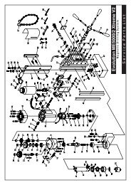
Fig 1<br />
ASSEMBLY<br />
Note: Some minor assembly is required to prepare this<br />
machine for use. Please refer to the Service Parts Diagram.<br />
Some of the following tasks can be carried out with the<br />
machine still in its packaging if desired.<br />
WARNING: Do not connect this machine to a power supply until<br />
assembly has been completed, and a thorough safety check of<br />
the machine and all of its systems has been carried out.<br />
Check that all the contents (as listed in this Instruction Manual)<br />
are present.<br />
Follow these instructions if the leg set and plastic lower safety<br />
guard are fastened to the machine.<br />
• Read and understand these instructions.<br />
• Visually check the inside of the machine body to locate<br />
any polystyrene transit packing. This polystyrene is present<br />
to provide protection for the machines internal components<br />
during shipping. It is not required operationally and must be<br />
removed before the machine can be used.<br />
• Remove 6 of the 8 cross-head screws which fasten the<br />
lower plastic safety guard to the body of the machine. The<br />
2 screws positioned underneath the sliding transportation<br />
handle can be left in place.<br />
• Carefully ease the guard upwards to gain access to the<br />
inside of the machine.<br />
• Reach inside and remove any transit packing present.<br />
• Replace the lower plastic safety guard and replace the<br />
6 cross-head screws.<br />
• Remove the machine from the packaging.<br />
WARNING: This machine is heavy. Enlist competent help<br />
when removing this machine from its packaging.<br />
1. Deploying the Legs<br />
The legs are stored underneath the machines main body.<br />
• Release the retaining hook found to the front of the machine.<br />
• Swing the legs outwards<br />
• Secure the legs by hooking the safety hook over the<br />
protruding metal screw.<br />
• Unhook and deploy the 2 rear cantilever braces and re-hook<br />
them into their operational position. (Fig. 1)<br />
Note: The cantilever braces, and one of the main legs have<br />
an adjustable foot which can be screwed in or out to obtain<br />
maximum stability for the machine, particularly on uneven<br />
surfaces.<br />
www.evolutionbuild.com<br />
9