Original Instructions - Evolution Power Tools Ltd.
Original Instructions - Evolution Power Tools Ltd.
Original Instructions - Evolution Power Tools Ltd.

Create successful ePaper yourself
Turn your PDF publications into a flip-book with our unique Google optimized e-Paper software.
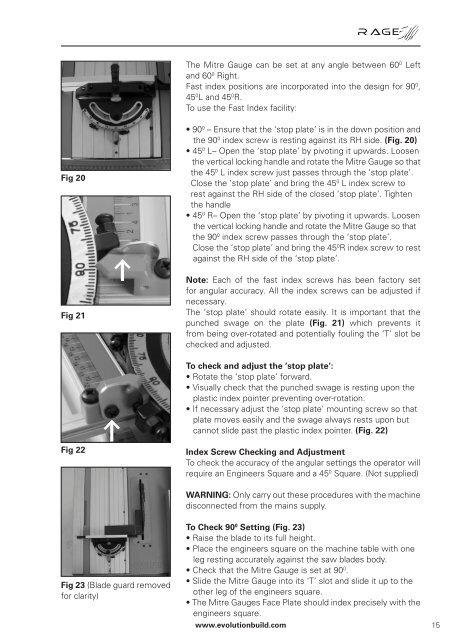
Fig 20<br />
Fig 21<br />
Fig 22<br />
Fig 23 (Blade guard removed<br />
for clarity)<br />
The Mitre Gauge can be set at any angle between 60 0 Left<br />
and 60 0 Right.<br />
Fast index positions are incorporated into the design for 90 0 ,<br />
45 0 L and 45 0 R.<br />
To use the Fast Index facility:<br />
• 90 0 – Ensure that the ‘stop plate’ is in the down position and<br />
the 90 0 index screw is resting against its RH side. (Fig. 20)<br />
• 45 0 L– Open the ‘stop plate’ by pivoting it upwards. Loosen<br />
the vertical locking handle and rotate the Mitre Gauge so that<br />
the 45 0 L index screw just passes through the ‘stop plate’.<br />
Close the ‘stop plate’ and bring the 45 0 L index screw to<br />
rest against the RH side of the closed ‘stop plate’. Tighten<br />
the handle<br />
• 45 0 R– Open the ‘stop plate’ by pivoting it upwards. Loosen<br />
the vertical locking handle and rotate the Mitre Gauge so that<br />
the 90 0 index screw passes through the ‘stop plate’.<br />
Close the ‘stop plate’ and bring the 45 0 R index screw to rest<br />
against the RH side of the ‘stop plate’.<br />
Note: Each of the fast index screws has been factory set<br />
for angular accuracy. All the index screws can be adjusted if<br />
necessary.<br />
The ‘stop plate’ should rotate easily. It is important that the<br />
punched swage on the plate (Fig. 21) which prevents it<br />
from being over-rotated and potentially fouling the ‘T’ slot be<br />
checked and adjusted.<br />
To check and adjust the ‘stop plate’:<br />
• Rotate the ‘stop plate’ forward.<br />
• Visually check that the punched swage is resting upon the<br />
plastic index pointer preventing over-rotation.<br />
• If necessary adjust the ‘stop plate’ mounting screw so that<br />
plate moves easily and the swage always rests upon but<br />
cannot slide past the plastic index pointer. (Fig. 22)<br />
Index Screw Checking and Adjustment<br />
To check the accuracy of the angular settings the operator will<br />
require an Engineers Square and a 45 0 Square. (Not supplied)<br />
WARNING: Only carry out these procedures with the machine<br />
disconnected from the mains supply.<br />
To Check 90 0 Setting (Fig. 23)<br />
• Raise the blade to its full height.<br />
• Place the engineers square on the machine table with one<br />
leg resting accurately against the saw blades body.<br />
• Check that the Mitre Gauge is set at 90 0 .<br />
• Slide the Mitre Gauge into its ‘T’ slot and slide it up to the<br />
other leg of the engineers square.<br />
• The Mitre Gauges Face Plate should index precisely with the<br />
engineers square.<br />
www.evolutionbuild.com<br />
15