FURY6 Instruction Manual - Evolution Power Tools Ltd.
FURY6 Instruction Manual - Evolution Power Tools Ltd.
FURY6 Instruction Manual - Evolution Power Tools Ltd.

You also want an ePaper? Increase the reach of your titles
YUMPU automatically turns print PDFs into web optimized ePapers that Google loves.
210mm TCT Multipurpose<br />
Mitre / Table Saw<br />
Original<br />
<strong>Instruction</strong>s<br />
Read instructions before operating this tool.<br />
www.evolutionfury.com<br />
®<br />
16.04.12_V9
2<br />
GB<br />
03<br />
www.evolutionfury.com
GB<br />
<strong>Instruction</strong> <strong>Manual</strong><br />
Read instructions before operating this tool.<br />
TABLE OF CONTENTS<br />
EC - Declaration of Conformity 4<br />
Important Information 5<br />
12 Month Limited Warranty 5<br />
General Safety Rules 5<br />
Additional Specific Safety Rules 7<br />
Safety Labels and Symbols 8<br />
Machine Overview 12-13<br />
Operation Mitre Saw 16<br />
Operation Table Saw 21<br />
Maintenance 24<br />
Environmental Protection 28<br />
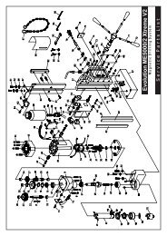
Service Parts Diagram 30<br />
www.evolutionfury.com 3
4<br />
EC - DECLARATION OF CONFORMITY<br />
We, manufacturer and importer<br />
<strong>Evolution</strong> <strong>Power</strong> <strong>Tools</strong> <strong>Ltd</strong>.<br />
Venture One<br />
Sheffield<br />
S20 3FR<br />
Declare that the product<br />
Part numbers:<br />
EVOLUTION FURY 6<br />
<strong>Evolution</strong>: TABLE MITRE SAW<br />
Complies with the essential requirements<br />
of the following European Directives:<br />
2006/42/EC – Machine Directive<br />
2006/95/EC – Low Voltage Directive<br />
2004/108/EC – EMC Directive<br />
2002/95/EC – Restriction of the use of<br />
Certain Hazardous Substances in Electrical<br />
and Electric Equipment<br />
Standards and Technical specifications<br />
referred to:-<br />
EN 61029-1<br />
EN 61029-2-11<br />
EN 55014-1<br />
EN 55014-2<br />
EN 61000-3-2<br />
EN 61000-3-3<br />
Authorised by<br />
Mr. Matthew J Gavins<br />
Managing Director<br />
31st January 2012<br />
All documentation is held on file at<br />
the above address and is available, on<br />
request for review.<br />
This manual was originally written in<br />
English.<br />
www.evolutionfury.com
IMPORTANT<br />
Please read these operating and safety<br />
instructions carefully and completely.<br />
For your own safety, before using this<br />
equipment check that the fitted plug and<br />
voltage are correct, and that all handles and<br />
parts are firmly secured. If you are uncertain<br />
about any aspect of using this equipment,<br />
please contact our Technical Helpline.<br />
Technical Helpline UK 0870 609 2297<br />
EVOLUTION TABLE MITRE SAW<br />
Congratulations on your purchase of an<br />
<strong>Evolution</strong> <strong>Power</strong> <strong>Tools</strong> Table Mitre Saw.<br />
Please complete your product registration<br />
online to validate your machine’s warranty<br />
period and ensure prompt service if needed.<br />
We sincerely thank you for selecting a<br />
product from <strong>Evolution</strong> <strong>Power</strong> <strong>Tools</strong>.<br />
12 MONTH LIMITED WARRANTY.<br />
<strong>Evolution</strong> power tools reserves the right<br />
to make improvements and modifications<br />
to design without prior notice.<br />
<strong>Evolution</strong> <strong>Power</strong> <strong>Tools</strong> will, within twelve<br />
(12) months from the original date of<br />
purchase, repair or replace any goods<br />
found to be defective in materials or<br />
workmanship. This warranty is void if the<br />
tool being returned has been used to cut<br />
materials beyond the recommendations in<br />
the <strong>Instruction</strong> <strong>Manual</strong> or if the machine<br />
has been damaged by accident, neglect, or<br />
improper service. This warranty does not<br />
apply to machines and / or components<br />
which have been altered, changed, or<br />
modified in any way, or subjected to use<br />
beyond recommended capacities and<br />
specifications. Electrical components<br />
are subject to respective manufacturers’<br />
warranties. All goods returned defective<br />
shall be returned prepaid freight to <strong>Evolution</strong><br />
<strong>Power</strong> <strong>Tools</strong>. <strong>Evolution</strong> <strong>Power</strong> <strong>Tools</strong> reserves<br />
the right to optionally repair or replace it with<br />
the same or equivalent item. There is no<br />
warranty – written or verbal – for saw blades.<br />
In no event shall <strong>Evolution</strong> <strong>Power</strong> <strong>Tools</strong> be<br />
liable for loss or damage resulting directly or<br />
indirectly from the use of our merchandise<br />
or from any other cause. <strong>Evolution</strong> <strong>Power</strong><br />
<strong>Tools</strong> is not liable for any costs incurred<br />
on such goods or consequential damages.<br />
No officer, employee or agent of <strong>Evolution</strong><br />
<strong>Power</strong> <strong>Tools</strong> is authorized to make oral<br />
representations of fitness or to waive any<br />
of the foregoing terms of sale and none<br />
shall be binding on <strong>Evolution</strong> <strong>Power</strong> <strong>Tools</strong>.<br />
Questions relating to this limited warranty<br />
should be directed to the company’s head<br />
office, or call the appropriate Helpline<br />
number.<br />
GENERAL SAFETY RULES<br />
WARNING: When using electric tools,<br />
basic safety precautions should always be<br />
followed to reduce the risk of fire, electric<br />
shock and personal injury.<br />
Please read all of these instructions<br />
before attempting to operate this<br />
machine. Save this manual for future<br />
reference.<br />
1. Keep work area clear. Cluttered work<br />
areas invite accidents.<br />
2. Consider work area environment. Do<br />
not expose tools to rain. Do not use tools<br />
in damp or wet locations. Keep work area<br />
well lit. Do not use tools in the presence of<br />
flammable liquids or gases.<br />
3. Guard against electric shock. Avoid<br />
body contact with earthed or grounded<br />
surfaces (e.g. pipes, radiators, ranges,<br />
refrigerators).<br />
4. Keep other people away. Do not let<br />
others, especially children, come close to the<br />
work, and touch the tool or the extension<br />
lead. Keep them away from the work area.<br />
5. Store idle tools. When not in use, tools<br />
should be stored in a dry locked-up place,<br />
out of reach of children.<br />
6. Do not force the tool. It will do the job<br />
better and safer at the rate for which it was<br />
intended<br />
7. Use the right tool. Do not force small<br />
tools to do the job of a heavy duty tool. Do<br />
www.evolutionfury.com 5
6<br />
not use tools for purposes not intended; for<br />
example do not use circular saws to cut tree<br />
limbs or logs.<br />
8. Dress properly. Do not wear loose<br />
clothing or jewellery, they can be caught<br />
in moving parts. Non-skid footwear is<br />
recommended when working outdoors.<br />
Wear protective hair covering to contain long<br />
hair.<br />
9. Use protective equipment. Use safety<br />
glasses. Use face or dust mask if working<br />
operations create dust.<br />
10. Connect dust extraction equipment.<br />
If the tool is provided for the connection of<br />
dust extraction and collection equipment,<br />
ensure these are connected and properly<br />
used.<br />
11. Do not abuse the cord. Never yank<br />
the cord to disconnect it from the socket.<br />
Keep the cord away from heat, oil and sharp<br />
edges.<br />
12. Secure work. Where possible, use<br />
clamps or a vice to hold the work. It’s much<br />
safer than using your hand.<br />
13. Don’t over reach. Keep proper footing<br />
and balance at all times.<br />
14. Maintain tools with care. Keep<br />
cutting tools sharp and clean for better and<br />
safer performance. Follow instructions for<br />
lubricating and changing accessories. Inspect<br />
tool cords periodically and, if damaged, have<br />
them repaired by an authorised service<br />
facility. Inspect extension cord periodically<br />
and replace immediately if damaged. Keep<br />
handles dry, clean and free from oil and<br />
grease.<br />
15. Disconnect tools. When not in use,<br />
before any servicing and when changing<br />
accessories such as blades, bits, cutters,<br />
disconnect tool from the power source<br />
16. Remove adjusting keys and spanners.<br />
Form the habit of checking to see the keys<br />
and adjusting spanners are removed from<br />
the tool before turning it on.<br />
17. Avoid unintentional starting. Ensure<br />
switch is in “off” position when plugging in.<br />
18. Use outdoor extension leads. When<br />
the tool is used outdoors, use only extension<br />
cords intended for outdoor use and so<br />
marked.<br />
www.evolutionfury.com<br />
19. Stay alert. Watch what you are doing,<br />
use common sense and do not operate the<br />
tool when you are tired.<br />
20. Check damaged parts. Before further<br />
use of tool, it should be carefully checked<br />
to determine that it will operate properly<br />
and perform the intended function. Check<br />
for alignment of moving parts, mountings<br />
and any other components that may affect<br />
its operation. A guard or other part that is<br />
damaged should be properly repaired or<br />
replaced by an authorised service centre<br />
unless otherwise indicated in this instruction<br />
manual. Have defective switches replaced by<br />
an authorised service centre. Do not use the<br />
tool if the switch does not turn it on and off.<br />
21. WARNING. The use of any<br />
accessory or attachment other than one<br />
recommended in this instruction manual<br />
may present a risk of personal injury.<br />
22. Have your tool repaired by a qualified<br />
person. This electric tool complies with<br />
relevant safety rules. Repairs should only be<br />
carried out by qualified persons using original<br />
spare parts. Otherwise this may result in<br />
considerable danger to the user.<br />
HEALTH ADVICE<br />
WARNING: When drilling, sanding, sawing<br />
or grinding, dust particles will be produced.<br />
In some instances, depending on the<br />
materials you are working with, this dust can<br />
be particularly harmful to you (e.g. lead from<br />
old gloss paint).You are advised to consider<br />
the risks associated with the materials you<br />
are working with and to reduce the risk of<br />
exposure.<br />
You should:<br />
• Work in a well-ventilated area.<br />
• Work with approved safety equipment,<br />
such as dust masks that are specially<br />
designed to filter microscopic particles.
ADDITIONAL SAFETY INSTRUCTIONS<br />
FOR YOUR TABLE MITRE SAW<br />
WARNING: Be sure to read and<br />
understand all instructions. Failure to<br />
follow all instructions listed below may<br />
result in electric shock, fire and/or serious<br />
personal injury.<br />
1. Know your power tool. Read operator’s<br />
manual carefully. Learn the applications and<br />
limitations, as well as the specific potential<br />
hazards related to this tool.<br />
2. Always wear safety glasses or eye<br />
shields when using this mitre saw.<br />
Everyday eyeglasses have only impactresistant<br />
lenses; they are not safety glasses.<br />
3. Always protect your lungs. Wear a face<br />
mask or dust mask if the operation is dusty.<br />
4. Always protect your hearing. Wear<br />
hearing protection during extended periods<br />
of operation.<br />
5. Inspect the machines power cord regularly<br />
and if damaged have it repaired or replaced.<br />
Always be aware of the cords location.<br />
6. Always check for damaged parts.<br />
Before further use of the tool, a guard<br />
or other part that is damaged should be<br />
carefully checked to determine if it will<br />
operate properly and perform its intended<br />
function. Check for misalignment or binding<br />
of moving parts, breakage of parts, and<br />
any other condition that may affect the<br />
tool’s operation. A guard or other part that<br />
is damaged should be properly repaired or<br />
replaced at a qualified service centre. Keep<br />
guards in place and in working order.<br />
7. Do not abuse the cord. Never use the<br />
cord to carry the tool or pull the plug<br />
from the outlet. Keep cord away from<br />
heat, oil, sharp edges or moving parts.<br />
Replace damaged cords immediately.<br />
Damaged cords increase the risk of electric<br />
shock.<br />
8. Always make sure that your extension<br />
cord is in good condition. When using an<br />
extension cord be sure to use one that is<br />
heavy enough to carry the current that your<br />
tool will draw. An undersized cord will cause<br />
a drop in line voltage, resulting in loss of<br />
power and overheating.<br />
9. Do not use the tool while tired or under<br />
the influence of drugs, alcohol or any<br />
medication. Following this rule will reduce<br />
the risk of electric shock, fire or serious<br />
personal injury.<br />
10. Save these instructions. Refer to<br />
them frequently and use them to instruct<br />
others who may use this tool. If someone<br />
borrows this tool, make sure they have<br />
these instructions also.<br />
11. When the correct blade to cut the<br />
material has been fitted, this saw is<br />
recommended for cutting steel and<br />
ferrous metals, aluminium and nonferrous<br />
metals, wood, and plastic only.<br />
12. Do not use saw blades with High<br />
Speed Steel (HSS) or blades that are<br />
damaged or deformed.<br />
13. Replace the table insert when worn.<br />
14. Use only saw blades recommended<br />
by the manufacturer and which are the<br />
exact bore and diameter required for this<br />
machine.<br />
15. Connect your mitre saw to a dust<br />
collecting device (O.D.Ø32mm) when<br />
sawing material likely to cause dust.<br />
16. Select saw blades in relation to the<br />
material to be cut. Use only genuine<br />
<strong>Evolution</strong> or <strong>Evolution</strong> recommended<br />
accessories.<br />
17. Check the maximum depth of cut.<br />
18. When sawing long work pieces,<br />
always use extra support to provide<br />
better support, and use clamps or other<br />
clamping devices.<br />
19. Make sure the operator is adequately<br />
trained in the use, adjustment and<br />
operation of the machine.<br />
20. Provide for adequate room lighting at<br />
your workplace or for adequate lighting<br />
of the immediate work area.<br />
21. Refrain from removing any cut-offs<br />
or other parts of the workpiece from<br />
the cutting area whilst the machine is<br />
running and the saw head is not in the<br />
rest position. Never reach around the saw<br />
blade. Turn off tool and wait for saw blade to<br />
stop before moving workpiece or changing<br />
settings.<br />
www.evolutionfury.com 7
8<br />
22. Never stand on this tool. Serious<br />
injuries could occur if this tool tips over and<br />
you come into contact with the saw blade.<br />
23. Reduce the risk of unintentional<br />
starting. Make sure switch is in off position<br />
before plugging in.<br />
25. Do not use the saw without the guards<br />
in position, especially after a mode change,<br />
and to keep guards in good working order<br />
and properly maintained.<br />
26. The Riving Knife shall not be thicker<br />
than the width of the groove cut by the<br />
saw blade and not thinner than the body<br />
of the blade.<br />
27. Ensure that the arm is securely fixed<br />
when beveling.<br />
28. Always put the push stick into<br />
storage when not in use.<br />
29. Keep the floor area free of loose<br />
material e.g. chips and off cuts.<br />
30. Ensure that the bench saw table is<br />
securely fixed at the chosen height.<br />
31. Ensure that the speed marked on the<br />
saw blade is at least equal to the speed<br />
marked on the saw.<br />
32. Ensure that the upper portion of the<br />
saw blade is completely enclosed in mitre<br />
saw mode.<br />
33. Refrain from removing any off cuts<br />
or other parts of the workpiece from<br />
the cutting area whilst the machine is<br />
running and the saw head is not in the<br />
rest position.<br />
34. The saw shall not be used for slotting<br />
(stopped groove).<br />
35. Always clamp the workpiece to the<br />
saw table in mitre saw mode. Ensure<br />
before each cut that the machine is stable.<br />
WARNING: The operation of any table mitre<br />
saw can result in foreign objects being<br />
thrown into your eyes, which can result in<br />
severe eye damage. Before beginning power<br />
tool operation, always wear safety goggles<br />
or safety glasses with side shield and a full<br />
face shield when needed.<br />
WARNING: If any parts are missing, do not<br />
operate your table mitre saw until the missing<br />
parts are replaced. Failure to follow this rule<br />
could result in serious personal injury.<br />
www.evolutionfury.com<br />
ADDITIONAL SAFETY ADVICE<br />
CARRYING YOUR TABLE MITRE SAW<br />
Safety Advice<br />
1. Although compact, this saw is heavy. To<br />
reduce the risk of back injury, get competent<br />
help whenever you have to lift the saw.<br />
2. To reduce the risk of back injury, hold the<br />
tool close to your body when lifting. Bending<br />
your knees so you can lift with your legs, not<br />
your back. Lift by using the handhold areas<br />
at each side of the machines base.<br />
3. Never carry the Table Mitre Saw by the<br />
power cord. Carrying the tool by the power<br />
cord could cause damage to the insulation<br />
or the wire connections resulting in electric<br />
shock or fire.<br />
4. Before moving the saw tighten the mitre<br />
and bevel locking screws to guard against<br />
sudden unexpected movement.<br />
5. Lock the Cutting Head in its lowest position.<br />
Ensure that the Cutting Head Locking Pin is<br />
completely engaged in its socket.<br />
WARNING: Do not use the blade guard as<br />
a ‘lifting point’. The power cord must be<br />
removed from the power supply before<br />
attempting to move the machine.<br />
• Lock the Cutting Head in the down<br />
position using the Cutting Head locking<br />
pin.<br />
• Loosen the Mitre Angle Locking Screw.<br />
Turn the table to either of its maximum<br />
settings.<br />
• Lock the table in position using the<br />
Locking Screw.<br />
• Use the two carry handle cut-outs<br />
machined into either side of the<br />
machine base, to transport the<br />
machine.<br />
Place the saw on a secure stationary<br />
work surface and check the saw over<br />
carefully.<br />
Check particularly the operation of all the<br />
machines safety features before attempting<br />
to operate the machine.
SAFETY LABELS & SYMBOLS<br />
WARNING: Do not operate machine if<br />
warning and/or instruction labels are missing<br />
or damaged. Contact <strong>Evolution</strong> <strong>Power</strong> <strong>Tools</strong><br />
for replacement labels.<br />
Symbol Description<br />
V Volts<br />
A Amperes<br />
Hz Hertz<br />
min-1 Speed<br />
~ Alternating Current<br />
No No Load Speed<br />
Wear Safety<br />
Goggles<br />
Wear Ear Protection<br />
Do Not Touch<br />
Wear Dust Protection<br />
Restriction<br />
of Hazardous<br />
Substances Directive<br />
CE certification<br />
Waste electrical and<br />
electronic equipment<br />
Only use genuine <strong>Evolution</strong> replacement<br />
saw blades. Unauthorized blades may<br />
be dangerous! Keep saw blades securely<br />
fastened. Check the blade flanges for debris<br />
before installing any new blade. Do not use dull,<br />
broken or damaged blades. Check the blade<br />
regularly for condition and wear. A damaged or<br />
worn blade should be replaced immediately.<br />
Beware of ejecting chips as they may be HOT.<br />
Always make provision for the safe handling of<br />
excess material. Keep machine base and rotary<br />
table free from dirt and other debris.<br />
To obtain an additional copy of your <strong>Manual</strong>,<br />
please contact <strong>Evolution</strong> <strong>Power</strong> <strong>Tools</strong> at:<br />
UK 0870 609 2297<br />
WEB www.evolutionpowertools.com<br />
www.evolutionfury.com 9
10<br />
FURY 6 TABLE MITRE SAW SPECIFICATION<br />
Designed to cut:<br />
Mild Steel<br />
Wood<br />
Aluminium<br />
Plastic<br />
Technical Data<br />
Motor (230V ~ 50 Hz) (Watts) 1200<br />
RPM No Load (min -1 ): 3500<br />
Recommended Maximum Duty Cycle (Minutes): 30<br />
Weight (kg): 9.45<br />
Blade Dimensions - Multipurpose TCT<br />
Diameter (mm): 210<br />
Number of Teeth: 20<br />
Bore Diameter (mm): 25.4<br />
Kerf thickness (mm): 1.7<br />
Maximum Cutting Capacity - Mild Steel 3 mm<br />
Maximum Cutting Capacity (Wood) Mitre Saw Configuration<br />
At 90 0 mitre x 90 0 bevel (mm): 115 x 55<br />
At 45 0 mitre x 90 0 bevel (mm): 65 x 55<br />
At 45 0 mitre x 45 0 bevel (mm):ww 40 x 25<br />
Maximum Cutting Capacity (Wood) Table Saw Configuration<br />
Maximum cutting depth (mm): 32 mm<br />
Noise and Vibration Data<br />
Sound pressure level: 106.3dB(A) K=3dB(A)<br />
Sound power level: 119.3dB(A) K=3dB(A)<br />
Vibration level: 2.5 m/S 2 K =1.5dB(A)<br />
The declared vibration total value has been measured in accordance with a standard test<br />
method and may be used for comparing one tool with another.<br />
The declared vibration total value may also be used in a preliminary assessment of exposure.<br />
WARNING: The vibration emission during actual use of the power tool can differ from the<br />
declared total value depending on the ways in which the tool is used. The need to identify<br />
safety measures and to protect the operator are based on an estimation of exposure in the<br />
actual conditions of use (taking account of all parts of the operating cycle, such as the times<br />
the tool is switched off, when it is running idle, in addition to trigger time).<br />
www.evolutionfury.com
Assembly<br />
Your <strong>Evolution</strong> <strong>Power</strong> <strong>Tools</strong> saw is shipped<br />
complete. Remove all contents from the<br />
box and inspect to ensure no damage was<br />
incurred during shipping, and that the items<br />
listed below are included.<br />
Items Supplied<br />
DESCRIPTION QUANTITY<br />
<strong>Instruction</strong> <strong>Manual</strong> 1<br />
Hold Down Clamp 1<br />
Push Stick 1<br />
Pin Spanner (Blade Change) 1<br />
Hex Key 6mm (Blade Change) 1<br />
Hex Key 4mm<br />
(Riving Knife Adjustment)<br />
1<br />
Multi-Purpose Blade (Fitted) 1<br />
Rip Fence/Bevel Guide Assembly 1<br />
Auxiliary Lower Blade Guard<br />
(Fitted)<br />
1<br />
Dust Bag Adaptor Tube 1<br />
Workpiece Supports 2<br />
Rear Stabilising Arms 2<br />
Additional Accessories<br />
In addition to the standard accessories<br />
supplied with this machine, other<br />
accessories are available to improve its<br />
performance, these include the following<br />
items:<br />
Specialist cutting blades – use only<br />
<strong>Evolution</strong> Blades with this machine.<br />
Additional accessories can be obtained by<br />
contacting your local dealer (or <strong>Evolution</strong><br />
<strong>Power</strong> <strong>Tools</strong>).<br />
Dust Bag as an optional accessory<br />
www.evolutionfury.com 11
12<br />
LH VIEW OF FURY 6 MITRE SAW CONFIGURATION<br />
5<br />
9<br />
8<br />
10<br />
1. CUTTING HANDLE<br />
2. ROTARY TABLE<br />
3. RETRACTABLE LOWER BLADE GUARD<br />
4. BLADE<br />
5. BEVEL LOCKING LEVER (Back of the machine)<br />
6. MITRE ANGLE LOCKING SCREW<br />
7. MITRE ANGLE SCALE<br />
www.evolutionfury.com<br />
8. FENCE<br />
9. HOLD DOWN CLAMP<br />
10. STABILISING ARMS (X2 Back of machine)<br />
11. CUTTING HEAD RELEASE LEVER<br />
12. TABLE HEIGHT ADJUSTING SCREW<br />
11<br />
1<br />
12<br />
3<br />
4<br />
2<br />
6<br />
7
LH VIEW OF FURY 6 TABLE SAW CONFIGURATION<br />
6<br />
4<br />
1. ON/OFF TRIGGER SWITCH (Inside handle)<br />
2. ON/OFF LATCHING SWITCHES<br />
3. CUTTING HANDLE<br />
4. TABLE TOP<br />
5. AUXILLIARY LOWER BLADE GUARD<br />
6. UPPER BLADE GUARD<br />
7. RIP FENCE<br />
8<br />
8. PUSH STICK<br />
9. MOUNTING HOLE<br />
(2 at the front and 2 under the stabilising arms)<br />
10. CUTTING HEAD LATCHING PIN<br />
(Not shown in this view)<br />
www.evolutionfury.com 13<br />
10<br />
7<br />
1<br />
3<br />
2<br />
5<br />
9
14<br />
GETTING STARTED<br />
WARNING: ALWAYS DISCONNECT<br />
THE SAW FROM THE POWER SOURCE<br />
BEFORE MAKING ANY ADJUSTMENTS.<br />
Refer to the “Service Parts Diagram”. Install<br />
a blade as detailed in the “Installing or<br />
Removing the Blade” section.<br />
NOTE: We recommend that the operator<br />
reads the ‘Important Information’ sticker<br />
applied to the table of the Fury6. Practicing<br />
and becoming familiar with the procedures<br />
outlined on this sticker will make subsequent<br />
adjustments/assembly or configuring fairly<br />
straightforward.<br />
PERMANENTLY MOUNTING THE <strong>FURY6</strong><br />
TABLE/MITRE SAW (Fig. 1)<br />
WARNING: To reduce the risk of injury from<br />
unexpected saw movement, place the saw<br />
in the desired location either on a workbench<br />
or other recommended leg set. The base of<br />
the saw has four holes to mount the mitre<br />
saw. If the saw is to be used in one location,<br />
permanently fasten it to the workbench or<br />
leg set using appropriate bolts with lock<br />
washers and nuts.<br />
NOTE: When permanently mounting the<br />
Fury6 we recommend that the four (4)<br />
rubber feet located underneath each of the<br />
mounting holes are removed and stored<br />
safely for possible future use.<br />
1. Tighten the mitre and bevel locks.<br />
2. Position the saw so other people cannot<br />
stand behind it. Thrown debris could injure<br />
people in its path.<br />
3. Place the saw on a firm, level surface<br />
where there is plenty of room for handling<br />
and properly supporting the workpiece.<br />
4. Support the saw so that the table is level<br />
and the saw does not rock.<br />
5. Bolt or clamp the saw to its support.<br />
www.evolutionfury.com<br />
1<br />
2<br />
3<br />
4<br />
5<br />
6<br />
7<br />
Fig. 1<br />
1) Hex headed bolt M8 X 75<br />
2) Spring washer<br />
3) Flat washer<br />
4) Mitre saw base<br />
5) Workbench<br />
6) Flat washer<br />
7) Spring washer<br />
8) Hex nut<br />
9) Lock nut<br />
For Portable Use (Fig. 2)<br />
M8 x 75<br />
NOTE: The Fury6 is designed to be a highly<br />
portable machine.<br />
For portable use the Fury6 must be fitted<br />
with the two (2) rear Stabilising Arms.<br />
To fit the Stabilising Arms:<br />
• Remove the cross head machine<br />
screws from the two (2) rear mounting<br />
positions.<br />
• Attach the Stabilising Arms with the<br />
machine screws, two per arm and<br />
tighten securely.<br />
NOTE: The Stabilising Arms are fitted with<br />
rubber feet. The base of the Fury6 is also fitted<br />
with four (4) identical rubber feet positioned<br />
underneath the mounting holes in the base.<br />
When used as a portable machine the six (6)<br />
rubber feet provide the security and stability<br />
necessary for safe operation.<br />
8<br />
9<br />
THESE ITEMS<br />
ARE NOT<br />
SUPPLIED
Fig. 2<br />
Fig. 3a<br />
Fig. 3b (Dust bag, not supplied)<br />
NOTE: When the machine is re-positioned<br />
the operator should ensure that none of<br />
the rubber feet become detached from<br />
the machine. The rubber feet can, in some<br />
circumstances, stick to some surfaces due<br />
to vacuum suction.<br />
If any of the rubber feet become detached or<br />
damaged they must be replaced.<br />
DUST BAG<br />
A Dust Bag (not supplied) can be fitted<br />
to the extraction port at the rear of the<br />
machine. (Fig. 3a & 3b)<br />
• Push the adaptor tube into the extraction<br />
port at the rear of the machine.<br />
• Slide the Dust Bag onto the adaptor tube<br />
ensuring that the spring clip grips the tube<br />
holding the Dust Bag securely in place.<br />
NOTE: For operational efficiency empty<br />
the Dust Bag when it becomes 2/3 full.<br />
Dispose of the contents of the Dust Bag in<br />
an environmentally responsible way. It may<br />
be necessary to wear a dust mask when<br />
emptying the Dust Bag<br />
WARNING: DO NOT USE A DUST BAG<br />
WHEN CUTTING STEEL.<br />
www.evolutionfury.com 15
16<br />
Fig. 4<br />
Fig. 5<br />
Fig. 6<br />
Fig. 7<br />
www.evolutionfury.com<br />
TO CONFIGURE THE <strong>FURY6</strong> FOR USE AS<br />
A MITRE SAW<br />
WARNING: Only carry out this procedure<br />
with the machine disconnected from the<br />
power source.<br />
Caution: The Fury6 has many built in safety<br />
features and safety interlocks. It is important<br />
that the following instructions, and those<br />
found on the label attached to the machine<br />
table are read, understood and acted<br />
upon. Failure to carry out the configuration<br />
procedure could result in damage to the<br />
machine and/or injury to the operator.<br />
• Loosen the table height adjustment<br />
screw. (Fig.4)<br />
• Raise the table top to its upmost position<br />
and tighten the height adjustment screw.<br />
(Fig. 5)<br />
• Slightly push down on the Cutting Head<br />
Handle.<br />
• Pull out the Cutting Head Latching Pin<br />
and allow the Cutting Head to rise to its<br />
upmost position. (Fig. 6)<br />
• Remove the Auxiliary Lower Blade Guard<br />
and store safely for future use.<br />
The Fury6 is now ready to use as a<br />
Mitre Saw. (Fig. 7)
Fig. 8<br />
Fig. 9<br />
WORKPIECE SUPPORTS (Fig. 8)<br />
Workpiece supports can be fitted to both<br />
sides of the machine base if required.<br />
• Loosen the relevant Workpiece Retaining<br />
Screw located in a socket at the top front<br />
of the machine base.<br />
• Insert the Workpiece Support into the<br />
holes machined in the base.<br />
NOTE: The Workpiece Support should be<br />
pushed ‘fully home’ into the machine base.<br />
Correct installation will require approximately<br />
65mm of the Workpiece Support to slide into<br />
the machine base.<br />
• Fasten the Workpiece Support into the<br />
base by tightening the Retaining Screw.<br />
Workpiece Supports can be very useful in<br />
providing extra support for long workpieces<br />
when using the Fury6 in Mitre Saw<br />
configuration.<br />
HOLD DOWN CLAMP (Fig. 9)<br />
A Hold Down clamp is supplied with the Fury6.<br />
Two sockets (one on either side) are<br />
incorporated into the rear of the machines<br />
fence.<br />
• Fit the pillar of the clamp into the socket<br />
that best suits the cutting application,<br />
ensuring that it is pushed fully down.<br />
• Tighten the fence thumbscrew to lock the<br />
pillar of the Hold Down Clamp into the<br />
fence socket.<br />
• Put the workpiece onto the rotary table<br />
and against the fence.<br />
• Adjust the Hold Down Clamp so that<br />
it securely holds the workpiece to the<br />
rotary table.<br />
• Before attempting any cutting check to<br />
ensure that the clamp does not interfere<br />
with the blade path as the Cutting Head<br />
is lowered.<br />
OPERATING INSTRUCTIONS<br />
MITRE SAW CONFIGURATION<br />
WARNING: It is important that the operator<br />
is adequately trained in the use, adjustment<br />
and operation of the machine, and has read<br />
the <strong>Instruction</strong> <strong>Manual</strong> before commencing<br />
operations.<br />
NOTE: We recommend that when the<br />
Fury6 is being used as a Mitre Saw, the<br />
complete Fence Assembly is removed from<br />
the machine as stored safely for future use.<br />
1. Releasing the Cutting Head<br />
NOTE: When configured in Mitre Saw<br />
mode the Cutting Head will be automatically<br />
locked in its upper position with the<br />
Retractable Lower Blade Guard completely<br />
covering the blade teeth.<br />
www.evolutionfury.com 17
18<br />
Fig. 10<br />
B<br />
Fig. 11<br />
No-Hands Zone<br />
280mm<br />
No-Hands Zone<br />
To release the Cutting Head press and hold<br />
the Cutting Head Release Lever.<br />
Gently press down on the Cutting Head<br />
Handle to lower the Cutting Head. The<br />
operation of the Retractable Lower Blade<br />
Guard is automatic.<br />
NOTE: We recommend that when the<br />
machine is not in use the Cutting Head<br />
is locked in its down position, with the<br />
Auxiliary Lower Blade Guard correctly<br />
installed and the Cutting Head Latching Pin<br />
fully engaged in its socket.<br />
A<br />
www.evolutionfury.com<br />
2. Preparing to make a cut<br />
• Avoid awkward operations and hand<br />
positions where a sudden slip could cause<br />
fingers or hands to move into the blade.<br />
• Cut only one workpiece at a time.<br />
• Clear everything except the workpiece and<br />
related support devices away from the<br />
blade before commencing operations.<br />
Fasten the workpiece using clamp(s) to<br />
hold the workpiece securely to the table<br />
and fence.<br />
3. Body and Hand position (Fig. 10)<br />
• Never place hands within the ‘no hands<br />
zone’ (at least 150mm away from the<br />
blade). Pictograms on the machines<br />
rotary table are provided as an aid to safe<br />
working practices. Keep hands away from<br />
the path of the blade.<br />
• Hold the workpiece firmly to the fence to<br />
prevent any movement. Use a Hold Down<br />
Clamp if possible but check that it is<br />
positioned that it does not interfere with<br />
the path of the blade or other moving<br />
machine parts.<br />
• Before attempting a cut, make a ‘dry run’<br />
with the power off so that you can see<br />
the path of the blade.<br />
• Keep hands in position until the ON/OFF<br />
trigger has been released and the blade<br />
has completely stopped.<br />
4. The Mitre Saw On/Off Trigger Switch<br />
Operation (Fig. 11-A)<br />
The On/Off Switch is a non-latching trigger<br />
type switch which is ergonomically located<br />
on the inside of the Cutting Head Handle.<br />
Operate the switch to turn on the machines<br />
motor. Release the switch to turn off the<br />
machines motor.<br />
NOTE: The Cutting Head cannot be lowered<br />
until the Cutting Head Release Lever is<br />
operated. (Fig. 11-B) The Blade will remain<br />
covered by the retractable guard until the<br />
Cutting Head is released. Operation of the<br />
Retractable Guard is automatic.
Fig. 12<br />
Fig. 13<br />
5. Chop Cutting<br />
The Cutting Head is gently pushed down to<br />
cut through the workpiece.<br />
• Place the workpiece on the Rotary Table and<br />
against the fence in the desired position.<br />
Secure with clamp(s) as appropriate.<br />
• Grasp the Cutting Handle.<br />
• Turn on the motor using the trigger<br />
switch and allow the blade to reach<br />
full operating speed.<br />
• Press and hold the Cutting Head Release<br />
Lever to release the Cutting Head.<br />
• Gently lower the Cutting Head to its lowest<br />
position, cutting through the workpiece.<br />
• After the cut is completed, turn off the<br />
motor by releasing the trigger switch.<br />
Allow the blade to come to a complete<br />
stop. Allow the Cutting Head to rise to its<br />
upper position.<br />
• Only remove your hands or the workpiece<br />
from the machine when the Cutting<br />
Head is in its upper position with the<br />
blade teeth completely covered by the<br />
Retractable Blade Guard.<br />
6. Mitre Cutting<br />
Any angle from 45 0 left to 45 0 right is<br />
available, and a protractor scale can be<br />
found to the front of the Rotary Table.<br />
Positive stops are provided for every 5 0 of<br />
angular movement.<br />
NOTE: The rotary table must always be locked<br />
into position with the Mitre Angle Locking<br />
Screw even if a positive stop is selected.<br />
To select a Mitre Angle:<br />
• Loosen the Mitre Angle Locking Screw.<br />
(Fig.12) This is found at the front RH side<br />
of the table near the 30 0 index mark.<br />
• Turn the Rotary Table to the required<br />
angle. To aid setting, an index mark is<br />
machined into the table just in front of the<br />
table insert.<br />
• Tighten the Mitre Angle Locking Screw<br />
securely when the desired angle has<br />
been selected.<br />
A Mitre Cut can now be made using the<br />
same techniques as previously described in<br />
Chop Cutting.<br />
7. Bevel Cutting<br />
The Cutting Head can be set at any angle up<br />
to 45 0 to the Left Hand side only.<br />
The Bevel Locking Lever is found at the<br />
rear of the machine. A protractor guide<br />
and pointer are incorporated into the bevel<br />
mechanism to aid setting. (Fig.13)<br />
To set a Bevel Angle:<br />
• Loosen the Bevel Lock Handle<br />
• Tilt the Cutting Head to the desired angle.<br />
Use the protractor guide to aid with setting.<br />
• Ensure that the Bevel Lock Handle is<br />
securely tightened when the desired<br />
angle has been achieved.<br />
A Bevel Cut can now be made using the<br />
same techniques as previously outlined.<br />
www.evolutionfury.com 19
20<br />
Fig. 14<br />
Fig. 15<br />
NOTE: Always make a ‘dry run’ with the<br />
machine switched ‘off’ so that the path of<br />
the blade can be checked. Some Bevel and<br />
Compound Cuts may require the Hold Down<br />
Clamp to be positioned to the RH side of the<br />
Cutting Head. This may be necessary to avoid<br />
interference with the blade and other parts of<br />
the machine as the Cutting Head is lowered.<br />
8. Fence Adjustment<br />
NOTE: The left hand side of the fence is<br />
provided with additional adjustments. The<br />
upper portion of the fence can slide to the<br />
left to provide clearance for the blade. This<br />
may be necessary when acute bevel angles<br />
are selected.<br />
www.evolutionfury.com<br />
To adjust the fence:<br />
• Loosen the thumbscrew. (Fig 14)<br />
• Slide the upper portion of the fence to<br />
the required position and tighten the<br />
thumbscrew.<br />
• Lower the Cutting Head to check the path<br />
of the blade. Ensure there is no interference<br />
with any other parts of the machine.<br />
9. Compound Cutting<br />
A Compound Cut is a combination of a Mitre<br />
Cut and Bevel Cut.<br />
• Set the Mitre Angle required as previously<br />
described.<br />
• Set the Bevel Angle as previously described.<br />
• Ensure the tightness of all adjustment/<br />
locking screws, and conduct a ‘dry run’ to<br />
check the path of the blade.<br />
• Make the cut as previously described.<br />
10. Cutting Bowed Material (Fig 15)<br />
Before cutting any workpiece, check to see<br />
if it is bowed. If it is bowed the workpiece<br />
must be positioned and cut as shown. Do not<br />
position the workpiece incorrectly or cut the<br />
workpiece without the support of the fence.<br />
11. Clearing Jammed Material<br />
• Turn mitre saw “OFF” .and allow the<br />
blade to come to a complete halt.<br />
• If possible allow the Cutting Head to rise<br />
to its upper position.<br />
• Unplug the Mitre Saw from the mains<br />
supply.<br />
• Carefully remove any jammed material<br />
from the machine.
Fig. 16<br />
Fig. 17<br />
Fig. 18<br />
TO CONFIGURE THE <strong>FURY6</strong> FOR USE AS<br />
A TABLE SAW<br />
WARNING: Do not cut metal or metallic<br />
materials when the machine is configured<br />
as a Table Saw.<br />
WARNING: Only carry out this procedure<br />
with the machine disconnected from the<br />
power supply.<br />
Caution: The Fury6 has many built in safety<br />
features and safety interlocks. It is important<br />
that the following instructions, and those<br />
found on the label attached to the machine<br />
table are read, understood and acted<br />
upon. Failure to carry out the configuration<br />
procedure could result in damage to the<br />
machine and/or injury to the operator.<br />
• Ensure that the Rotary Table is set at 0 0<br />
Mitre angle and the Cutting Head is set at<br />
0 0 Bevel angle.<br />
• Position the Auxiliary Lower Blade Guard<br />
on the Rotary Table over the table insert<br />
and straddling the Fence. (Fig. 16)<br />
• Lower the Cutting Head to the fully down<br />
position, ‘capturing’ the Lower Auxiliary<br />
Blade Guard. Push the Cutting Head<br />
Latching Pin into its socket. (Fig. 17)<br />
• Loosen the Table Height Adjustment<br />
Screw (Fig.18) and lower the table to its<br />
lowest position.<br />
• Tighten the Height Adjustment Screw.<br />
The Fury6 is now ready to use as a<br />
Table Saw.<br />
www.evolutionfury.com 21
22<br />
Fig. 19<br />
Fig. 20<br />
Fig. 21<br />
height<br />
www.evolutionfury.com<br />
FENCE ASSEMBLY (Fig. 19)<br />
The Fence Assembly consists of two (2)<br />
main parts:<br />
• The Angle Gauge.<br />
• The Rip Fence Face Plate.<br />
NOTE: The ‘T’ slot in the Rip Fence Face<br />
Plate is not centrally located.<br />
• Slide the Rip Fence Face Plate onto the<br />
two (2) mounting screws found on the<br />
Angle Plate.<br />
• Ensure that the wider (20mm) portion of<br />
the Fence Face is downwards and will lie<br />
on the saw table when in use.<br />
The Angle Plate can now be slid into the<br />
Rip Fence channel found at the front of the<br />
machine table. (Fig. 20)<br />
Slide in from the Right Hand side ensuring<br />
that the Locking Clamp engages correctly<br />
with the front face of the Rip Fence channel.<br />
FENCE ASSEMBLY AS A RIP FENCE<br />
To use the Fence Assembly as a Rip Fence<br />
the Face Plate must be accurately aligned<br />
with the blade.<br />
WARNING: Only carry out this procedure<br />
with the machine disconnected from the<br />
power supply.<br />
To Align the Rip Fence:<br />
• Ensure that the table is at its lowest<br />
setting (see Fig. 23a &23b)<br />
• Set the Angle Gauge to an indicated 90 0 .<br />
• Slide the Fence Assembly up to the blade,<br />
raising the Blade Guard by hand so that the<br />
Face Plate rests alongside the blade and<br />
underneath the Blade Guard. (Fig.21)<br />
Gently tighten the Angle Gauge Locking<br />
Clamp Screw to lock the Assembly into<br />
the Rip Fence channel.<br />
• Check that the Face Plate is in exact<br />
alignment with the blade.<br />
• If adjustment is required, loosen slightly<br />
the Angle Clamping Screw and adjust<br />
the Angle Gauge until exact alignment is<br />
achieved.
Fig. 22<br />
Fig. 23a<br />
Fig. 23b<br />
• Tighten the Angle Clamping Screw.<br />
• Adjust the Angle Gauge Pointer if<br />
necessary to point exactly to the 90 0<br />
index mark.<br />
• Use a #2 Phillips Head screwdriver to<br />
loosen the Angle Pointer fixing screw.<br />
(Fig. 22) Adjust the pointer to suit and<br />
then retighten the fixing screw.<br />
• Loosen the Angle Clamp Locking Screw<br />
to allow the Assembly to slide along the<br />
Rip Fence channel.<br />
Basic Table Saw Operations<br />
WARNING: Do not cut metal or metallic<br />
materials when the machine is configured<br />
as a Table Saw.<br />
WARNING: Never attempt freehand cuts<br />
on this machine. Always use a correctly<br />
adjusted Rip Fence to minimise the<br />
possibility of the blade binding and kickback.<br />
1. Adjusting the Table Height<br />
(Fig. 23a &23b)<br />
The height of the Table above the machines<br />
motor can be adjusted. This enables your<br />
Fury6 to mimic the rise and fall facility found<br />
on many conventional table saws. The<br />
cutting depth of the blade can thereby be<br />
adjusted from 0mm to 32mm.<br />
WARNING: Only adjust the height of the<br />
table with the machine disconnected from<br />
the mains power supply.<br />
To adjust:<br />
• Loosen the Height Adjustment Screw and<br />
adjust the table height so that the saw<br />
blade protrudes through the table by the<br />
required amount. Retighten the screw.<br />
We recommend that the saw blade<br />
protrudes through the material to be<br />
cut by approximately 3mm.<br />
WARNING: This machine is not suitable for<br />
cutting rebates or stopped grooves.<br />
www.evolutionfury.com 23
24<br />
Fig. 24<br />
Fig. 25<br />
NOTE: A workshop dust extraction device<br />
can be connected to the extraction port<br />
found at the rear of the machine if required.<br />
2. Table Saw On/Off Switches (Fig. 24)<br />
The On/Off Switch is a two (2) button<br />
latching type. The buttons are located on the<br />
Front Left Hand side of the Cutting Handle.<br />
• Push the Green (I) button to start the motor.<br />
• Push the Red (O) button to stop the motor.<br />
3. Rip cutting<br />
NOTE: The Fury6 in Table Saw mode is<br />
optimally suited for the cutting of thin sheet<br />
material such as laminate flooring etc.<br />
Rip cutting is cutting along the length of a<br />
piece of material rather than across it.<br />
Rip cutting should always be done with the<br />
Rip Fence set to the desired width and on<br />
the RH side of the machines table.<br />
www.evolutionfury.com<br />
NOTE: Check that the Rip Fence is locked<br />
in position and is parallel to the saw blade.<br />
Check that the riving knife is properly<br />
aligned with the saw blade.<br />
When ripping small section material a Push<br />
Stick should be used to feed/guide the final<br />
300mm of the material past the blade. A<br />
Push Stick should always be used when<br />
making cuts of less than 300mm.<br />
NOTE: A Push Stick (Fig. 25) is provided<br />
with the Fury6 and has a dedicated storage<br />
position to the front of the machine.<br />
We recommend that when not in use the<br />
Push Stick is stored on the machine.<br />
When ripping long boards or large panels<br />
always use a remote work support or enlist<br />
competent trained help.<br />
Feed the workpiece through the saw<br />
keeping it indexed against the Rip Fence.<br />
Use smooth, steady pressure and employ a<br />
Push Stick when necessary.<br />
Hands should never be in line with the<br />
blade.<br />
MAINTENANCE AND ADJUSTMENTS<br />
WARNING: Ensure that the machine is<br />
disconnected from the mains supply before<br />
any maintenance tasks or adjustments are<br />
attempted.<br />
Cleaning<br />
After each use the machine should be<br />
cleaned. Remove all sawdust etc from the<br />
visible parts of the machine with a vacuum<br />
cleaner. A vacuum cleaner can also be<br />
connected to the machine dust extraction<br />
port at the rear of the machine. This should<br />
remove debris from the inside of the<br />
machine. Never use solvents to clean plastic<br />
parts, as solvents can damage them. Clean<br />
only with a soft slightly damp cloth.
Fig. 26<br />
Fig. 27<br />
Fig. 28<br />
Riving Knife<br />
The Riving Knife is a very important<br />
component and comes factory fitted and<br />
correctly aligned and adjusted. The Riving<br />
Knife prevents the work from binding as<br />
it passes through the blade. Inspect the<br />
Riving Knife at regular intervals and replace<br />
it if it is worn or damaged.<br />
The Riving Knife should be adjusted so<br />
that the gap between the tips of the blade<br />
teeth and the edge of the Riving Knife is<br />
approximately 3-5mm. (Fig.26)<br />
To adjust the Riving Knife loosen the two (2)<br />
fixing screws (Fig. 27) slightly using an allen<br />
key. When correct alignment is achieved<br />
tighten the fixing screws.<br />
NOTE: Use only a genuine <strong>Evolution</strong><br />
Riving Knife, as this is a dedicated<br />
component for this machine. Non genuine<br />
parts could be dangerous. If in any doubt,<br />
please contact the Helpline.<br />
Push Stick<br />
A plastic push stick is provided with the<br />
machine. When not in use store the push<br />
stick on the machine.<br />
NOTE: If the push stick becomes damaged<br />
it should be replaced. If the operator makes<br />
their own push stick, we recommend that it<br />
follows the same pattern as that supplied.<br />
Replacement push sticks are available from<br />
<strong>Evolution</strong> <strong>Power</strong> <strong>Tools</strong>.<br />
INSTALLING or REMOVING a BLADE<br />
WARNING: Only use genuine <strong>Evolution</strong><br />
blades which are designed for use in this<br />
machine. Ensure that the maximum speed<br />
of the blade is compatible with the machine.<br />
Only perform this operation with the machine<br />
disconnected from the mains supply.<br />
NOTE: It is recommended that the operator<br />
considers wearing protective gloves when<br />
handling the blade during installation or<br />
when changing the machines blade.<br />
NOTE: The blade is a very precise fit<br />
within the Fury6 machine. Be patient and<br />
methodical when changing the blade.<br />
To change a blade:<br />
• Ensure that the machine is in Mitre Saw<br />
Mode with the Cutting Head in its upper<br />
position.<br />
• Release the Retractable Lower Guard<br />
Operating Lever by removing and safely<br />
storing its pivot screw. (Fig. 28)<br />
www.evolutionfury.com 25
26<br />
Fig. 29<br />
Fig. 30<br />
• Use the pin spanner (provided) to hold<br />
the outer blade flange.<br />
• Use the hex key (provided) to unscrew<br />
the arbor screw. (Fig. 29)<br />
NOTE: The arbor screw has a Left Hand<br />
thread. Turn clockwise to undo and<br />
counterclockwise to tighten.<br />
• Remove the arbor screw, washer and<br />
outer blade flange.<br />
• <strong>Manual</strong>ly operate the Lower Blade Guard<br />
and retract it fully up into the body of the<br />
machine<br />
• Remove the blade by withdrawing it<br />
outwards to clear the end of the arbor and<br />
then downwards and forwards away from<br />
the machine.<br />
www.evolutionfury.com<br />
NOTE: The 5mm blade slot at the lower<br />
front of the Cutting Head (Fig. 30) provides<br />
extra clearance when manoeuvring the<br />
blade into or out of the machine.<br />
To refit:<br />
• Ensure that the blade is suitable for this<br />
machine.<br />
• Ensure that the direction of rotation arrow<br />
on the blade matches the direction of<br />
rotation arrow found on the machines Side<br />
Blade Guard. The blade teeth should always<br />
point downward at the front of the saw.<br />
• Using the blade slot to provide maximum<br />
clearance and access to the machine,<br />
carefully and gently manoeuvre the blade<br />
up into the machine and locate it on the<br />
inner blade flange.<br />
• Reinstall the outer blade flange, washer<br />
and arbor screw.<br />
• Hand tighten the assembly.<br />
• Hold the outer blade flange with the pin<br />
spanner.<br />
• Tighten the arbor screw with the hex key.<br />
• Check that the blade spins freely by<br />
rotating it by hand.<br />
• Close the Retractable Blade Guard<br />
around the blade so the blade teeth are<br />
completely covered.<br />
• Re-connect the Retractable Blade Guard<br />
Operating Lever to its service position<br />
using the pivot screw.<br />
• Check the installation, particularly for the<br />
operation of all the safety guards.<br />
CHECKING AND SETTING OF<br />
BEVEL ANGLES<br />
WARNING: Before making any adjustments<br />
ensure that the machine is disconnected<br />
from the power supply.<br />
NOTE: While all angular settings have been<br />
factory set, checking and adjustment may<br />
be required as a consequence of normal<br />
operational wear and tear.
Fig. 31<br />
Fig. 32<br />
NOTE: To check and adjust the Bevel<br />
Angles the machine must be in Mitre Saw<br />
configuration.<br />
0 0 BEVEL ANGLE<br />
At 0 0 Bevel Angle the blade should be<br />
perpendicular and at exactly 90 0 to the<br />
Rotary Table. An accurate engineers square<br />
(not supplied) is needed to check the 0 0<br />
Bevel Angle.<br />
To check:<br />
• Ensure that the Cutting Head is in the<br />
vertical position, against its stop with the<br />
Bevel Pointer indicating 0 0 Bevel Angle.<br />
• Tighten the Bevel Lock Handle.<br />
• Lower the Cutting Head to its lowest<br />
position. The Retractable Lower Blade<br />
Guard will rotate up into the machine.<br />
• The engineers square can now be used to<br />
check the angle between the blade and<br />
the Rotary Table.<br />
If adjustment is required:<br />
NOTE: The Cutting Head will need to be<br />
tilted to gain access to the 0 0 Bevel Stop<br />
Adjustment Screw.<br />
• Loosen slightly the 0 0 Bevel Stop<br />
Adjustment Screw locknut. (Fig. 31)<br />
• Use an Allen Key to turn the Bevel Stop<br />
Screw clockwise or counterclockwise<br />
as required.<br />
• When exact alignment between the<br />
blade and Rotary Table is achieved,<br />
tighten the locknut.<br />
45 0 BEVEL ANGLE<br />
The 45 0 Bevel Angle can be checked in a<br />
similar manner to the 0 0 Bevel Angle. An<br />
accurate 45 0 Engineers Set Square (not<br />
supplied) will be required.<br />
To check:<br />
• Ensure that the Cutting Head is tilted to<br />
the 45 0 position, against its stop, with the<br />
Bevel Pointer indicating 45 0 Bevel Angle.<br />
• Tighten the Bevel Lock Handle.<br />
• Lower the Cutting Head to its lowest<br />
position. The Retractable Lower Blade<br />
Guard will rotate up into the machine.<br />
• Use the Engineers 45 0 Set Square to<br />
check the angle of between the blade<br />
and the Rotary Table.<br />
If adjustment is required:<br />
NOTE: The Cutting Head will need to be<br />
tilted to gain access to the 45 0 Bevel Stop<br />
Adjustment Screw.<br />
• Loosen slightly the 45 0 Bevel Stop<br />
Adjustment Screw locknut. (Fig. 32)<br />
• Use a Hex Key to turn the Bevel Stop<br />
Screw clockwise or counterclockwise<br />
as required.<br />
• When exact alignment between the<br />
blade and Rotary Table is achieved,<br />
tighten the locknut.<br />
www.evolutionfury.com 27
28<br />
Fig. 33a<br />
Fig. 33b<br />
FENCE ADJUSTMENT (Fig. 33a & 33b)<br />
The Fence is fastened to the machines<br />
base by two (2) socket head screws, one<br />
on either side. These Screws are located in<br />
elongated holes, which enable the Fence to<br />
be repositioned as required.<br />
The Fence should be set at exactly 90 0 to a<br />
correctly installed blade.<br />
An accurate Engineers Square (not supplied)<br />
will be required to precisely position the Fence.<br />
To reposition the Fence:<br />
• Set the Rotary Table to 0 0 Mitre Angle.<br />
• Set the Cutting Head to 0 0 Bevel Angle.<br />
• Slightly loosen the two (2) Fence socket<br />
head screws.<br />
• Lower the Cutting Head to its lowest<br />
position.<br />
• Check the alignment of the Fence with<br />
the Blade using the Engineers Square.<br />
• Align the Fence as necessary and then<br />
tighten the socket head screws.<br />
www.evolutionfury.com<br />
FUSE AND PLUG REPLACEMENT<br />
Should the fuse in the main plug of your<br />
machine need replacing it should always be<br />
replaced with one of identical rating.<br />
Check the voltage given on your machine<br />
matches the supply voltage.<br />
This machine is supplied with a fitted<br />
moulded plug. If you should need to fit a<br />
new plug follows the protocol below.<br />
IMPORTANT<br />
The wire in the mains lead are coloured in<br />
accordance with the following code:<br />
Blue --- Neutral<br />
Brown --- Live<br />
The wire that is coloured blue must be<br />
connected to the terminal that is marked<br />
with the letter N. The wire that is coloured<br />
brown must be connected to the terminal<br />
that is marked with the letter L.<br />
A 13AMP (BS1363 or BS1363/A) plug must<br />
be used and a 13 AMP fuse must be fitted.<br />
ENVIRONMENTAL PROTECTION<br />
Waste electrical products should not be<br />
disposed of with household waste. Please<br />
recycle where facilities exist. Check with your<br />
Local Authority or retailer for recycling advice.
www.evolutionfury.com 29
30<br />
www.evolutionfury.com
www.evolutionfury.com 31
UK ADDRESS:<br />
<strong>Evolution</strong> <strong>Power</strong> <strong>Tools</strong>,<br />
Venture One, Longacre Close, Holbrook<br />
Industrial Estate, Sheffield, S20 3FR<br />
TEL: +44 (0) 114 251 1022<br />
FAX: +44 (0) 114 247 3339<br />
®