ECOR264- DVR manual-4605XCOR04004AR - Everfocus
ECOR264- DVR manual-4605XCOR04004AR - Everfocus
ECOR264- DVR manual-4605XCOR04004AR - Everfocus

You also want an ePaper? Increase the reach of your titles
YUMPU automatically turns print PDFs into web optimized ePapers that Google loves.
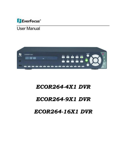
User Manual<br />
<strong>ECOR264</strong>-4X1 <strong>DVR</strong><br />
<strong>ECOR264</strong>-9X1 <strong>DVR</strong><br />
<strong>ECOR264</strong>-16X1 <strong>DVR</strong>
E V E R F O C U S E L E C T R O N I C S C O R P O R A T I O N<br />
<strong>ECOR264</strong>-4X1 <strong>DVR</strong><br />
<strong>ECOR264</strong>-9X1 <strong>DVR</strong><br />
<strong>ECOR264</strong>-16X1 <strong>DVR</strong><br />
Instruction Manual<br />
© 2010 EverFocus Electronics Corp<br />
www.everfocus.com<br />
All rights reserved. No part of the contents of this <strong>manual</strong> may be reproduced or transmitted in any form or by<br />
any means without written permission of the <strong>Everfocus</strong> Electronics Corporation.<br />
Release Date: Apr. 2010<br />
QuickTime is a registered trademark of the Apple Computer, Inc.<br />
Windows is a registered trademark of the Microsoft Corporation.<br />
Linksys is a registered trademark of the Linksys Corporation.<br />
D-Link is a registered trademark of the D-Link Corporation.<br />
DynDNS is a registered trademark of the DynDNS.org Corporation.<br />
Other product and company names mentioned herein may be the trademarks of their respective owners.
Safety Precautions<br />
Refer all work related to the installation of this product to qualified service personnel or system<br />
installers.<br />
Do not block the ventilation openings or slots on the cover.<br />
Do not drop metallic parts through slots. This could permanently damage the appliance. Turn the<br />
power off immediately and contact qualified service personnel for service.<br />
Do not attempt to disassemble the appliance. To prevent electric shock, do not remove screws or<br />
covers. There are no user-serviceable parts inside. Contact qualified service personnel for<br />
maintenance. Handle the appliance with care. Do not strike or shake, as this may damage the<br />
appliance.<br />
Do not expose the appliance to water or moisture, nor try to operate it in wet areas. Do take immediate<br />
action if the appliance becomes wet. Turn the power off and refer servicing to qualified service<br />
personnel. Moisture may damage the appliance and also may cause electric shock.<br />
Do not use strong or abrasive detergents when cleaning the appliance body. Use a dry cloth to clean<br />
the appliance when it is dirty. When the dirt is hard to remove, use a mild detergent and wipe gently.<br />
Do not overload outlets and extension cords as this may result in a risk of fire or electric shock.<br />
Do not operate the appliance beyond its specified temperature, humidity or power source ratings. Do<br />
not use the appliance in an extreme environment where high temperature or high humidity exists. Use<br />
the <strong>DVR</strong> at indoor type temperatures within 0°C~40°C (32°F~104°F) and at relative humidity between<br />
20%~80%. The input power source for this device is 12VDC though a power supply which operates<br />
from100~240VAC.<br />
Read Instructions<br />
All the safety and operating instructions should be read before the unit is operated.<br />
Retain Instructions<br />
The safety and operating instructions should be retained for future reference.<br />
Heed Warnings<br />
All warnings on the unit and in the operating instructions should be adhered to.<br />
Follow Instructions<br />
All operating and use instructions should be followed.<br />
Cleaning<br />
ii
Unplug the unit from the outlet before cleaning. Do not use liquid cleaners, abrasive or aerosol<br />
cleaners. Use a damp cloth for cleaning<br />
Attachments<br />
Do not use attachments not recommended by the product manufacturer as they may cause hazards.<br />
Water and Moisture<br />
Do not use this unit near water-for example, near a bath tub, wash bowl, kitchen sink, or laundry tub,<br />
in a wet basement, near a swimming pool, in an unprotected outdoor installation, or any area which is<br />
classified as a wet location.<br />
Servicing<br />
Do not attempt to service this unit by yourself as opening or removing covers may expose you to<br />
dangerous voltage or other hazards. Refer all servicing to qualified service personnel.<br />
Power Cord Protection<br />
Power supply cords should be routed so that they are not likely to be walked on or pinched by items<br />
placed upon or against them, playing particular attention to cords and plugs, convenience receptacles,<br />
and the point where they exit from the appliance.<br />
Object and Liquid Entry<br />
Never push objects of any kind into this unit through openings as they may touch dangerous voltage<br />
points or short-out parts that could result in a fire or electric shock. Never spill liquid of any kind on the<br />
unit.<br />
ATTENTION! This is a class A product which may cause radio interference in a domestic environment; in<br />
this case, the user may be urged to take adequate measures.<br />
Federal Communication Commission Interference Statement<br />
This equipment has been tested and found to comply with the limits for a Class B digital device, pursuant to<br />
Part 15 of the FCC Rules. These limits are designed to provide reasonable protection against harmful<br />
interference in a residential installation. This equipment generates, uses and can radiate radio frequency<br />
energy and, if not installed and used in accordance with the instructions, may cause harmful interference to<br />
radio communications. However, there is no guarantee that interference will not occur in a particular<br />
installation. If this equipment does cause harmful interference to radio or television reception, which can be<br />
determined by turning the equipment off and on, the user is encouraged to try to correct the interference by<br />
one of the following measures :<br />
•Reorient or relocate the receiving antenna.<br />
•Increase the separation between the equipment and receiver.<br />
•Connect the equipment into an outlet on a circuit different from that to which the receiver is connected.<br />
•Consult the dealer or an experienced radio/TV technician for help.<br />
FCC Caution: Any changes or modifications not expressly approved by the party responsible for compliance<br />
could void the users’ authority to operate this equipment.<br />
iii
WEEE<br />
This Product is RoHS compliant.<br />
The information in this <strong>manual</strong> was current upon publication. The manufacturer reserves the right to revise and improve his products.<br />
Therefore, all specifications are subject to change without prior notice. Manufacturer is not responsible for misprints or typographical<br />
errors.<br />
Please read this <strong>manual</strong> carefully before installing and using this unit. Be sure to keep it handy for later reference.<br />
iv<br />
iv
TABLE OF CONTENTS<br />
1 PRODUCT OVERVIEW ..................................................................................................... 1<br />
1.1 FEATURES ....................................................................................................................... 1<br />
1.2 PACKAGE CONTENTS................................................................................................... 2<br />
1.3 SPECIFICATIONS ........................................................................................................... 3<br />
1.4 FRONT PANEL ................................................................................................................ 5<br />
1.5 REAR PANEL................................................................................................................... 7<br />
1.6 VIDEO INPUTS/OUTPUTS INSTALLATION............................................................... 9<br />
1.7 AUDIO INSTALLATION ................................................................................................ 9<br />
1.8 ALARM CONTACTS INSTALLATION......................................................................... 9<br />
1.8.1 Alarm Input Contacts ..............................................................................................................................9<br />
1.8.2 Alarm Output Relay...............................................................................................................................10<br />
1.9 RS-485 KEYBOARD / PTZ INSTALLATION......................................................................... 10<br />
1.9.1 General RS-485 bus installation ...........................................................................................................10<br />
1.9.2 RS-485 socket pin assignment ...............................................................................................................12<br />
1.9.3 EKB-500 connection with network patch cable.....................................................................................12<br />
1.9.4 EKB-500 connection to several <strong>DVR</strong>s...................................................................................................12<br />
1.9.5 Speed Dome Installation .......................................................................................................................12<br />
1.10 USB-MOUSE INSTALLATION.......................................................................................... 13<br />
1.11 NETWORK CONNECTION........................................................................................ 13<br />
1.11.1 Direct PC Connection through Crossover Network Cable ...................................................................13<br />
1.11.2 Network Connection through Patch Cable............................................................................................14<br />
1.12 FINAL INSTALL PROCESS....................................................................................... 14<br />
2 MOUSE AND FRONT PANEL OPERATION ............................................................... 15<br />
2.1 GENERAL USB MOUSE OPERATION ....................................................................... 15<br />
2.1.1 How to select a channel / Enable audio ................................................................................................15<br />
2.1.2 OSD Root Menu ....................................................................................................................................15<br />
2.1.3 Operation in the Configuration Menus .................................................................................................16<br />
2.1.4 Field Input Options ...............................................................................................................................16<br />
2.2 GENERAL FRONT PANEL OPERATION ............................................................................... 18<br />
2.2.1 How to select a channel / Enable audio .......................................................................................................18<br />
2.2.2 OSD Root Menu ...........................................................................................................................................18<br />
2.2.3 Front Panel Key Review...............................................................................................................................18<br />
2.2.4 Operation in Configuration Menu.........................................................................................................18<br />
2.2.5 Field Input Options ...............................................................................................................................19<br />
3. GENERAL <strong>DVR</strong> OPERATIONS...................................................................................... 21<br />
3.1 RECORD......................................................................................................................... 21<br />
3.2 LOGIN............................................................................................................................. 21<br />
3.3 SELECT CAMERA OPERATION................................................................................. 22<br />
3.5 PLAYBACK.................................................................................................................... 23<br />
v
3.6 PTZ .................................................................................................................................. 24<br />
3.6.1 General PTZ control (if PTZ cameras are installed)..................................................................................24<br />
3.6.2 Express Control of PTZ.........................................................................................................................25<br />
3.7 LAYOUT......................................................................................................................... 27<br />
3.7.1 Bring a camera to full screen mode ......................................................................................................27<br />
3.8 CHANNEL SWITCHING............................................................................................... 27<br />
3.9 DISPLAY ........................................................................................................................ 28<br />
3.10 SEQUENCE.................................................................................................................. 28<br />
3.11 ZOOM........................................................................................................................... 28<br />
3.12 SEARCH....................................................................................................................... 30<br />
3.12.1 Time Search...........................................................................................................................................30<br />
3.12.2 Event Search..........................................................................................................................................31<br />
3.12.3 Smart Search .........................................................................................................................................32<br />
3.12.4 Snapshot Search ....................................................................................................................................35<br />
3.13 COPY............................................................................................................................ 37<br />
3.14 LOGOUT ...................................................................................................................... 38<br />
4 <strong>DVR</strong> CONFIGURATION.................................................................................................. 39<br />
4.1 CONFIGURATION MENU............................................................................................ 39<br />
4.2 EXPRESS ........................................................................................................................ 39<br />
4.3 CAMERA SETTING ...................................................................................................... 42<br />
4.3.1 Basic Setting..........................................................................................................................................42<br />
4.3.2 Video Adjust ..........................................................................................................................................45<br />
4.3.3 Motion ...................................................................................................................................................46<br />
4.3.4 Video Loss .............................................................................................................................................49<br />
4.4 RECORD & PLAY SETTING........................................................................................ 50<br />
4.4.1 Record ...................................................................................................................................................51<br />
4.4.2 Built-in Calculator ................................................................................................................................51<br />
4.4.3 Play .......................................................................................................................................................53<br />
4.5 ALARM & EVENT SETTING....................................................................................... 54<br />
4.5.1 Alarm.....................................................................................................................................................54<br />
4.5.2 Event......................................................................................................................................................57<br />
4.6 SCHEDULE SETTING................................................................................................... 66<br />
4.6.1 Express Setup .......................................................................................................................................66<br />
4.6.2 Holidays ................................................................................................................................................67<br />
4.6.3 Schedule ................................................................................................................................................68<br />
4.6.4 Alarm Action .........................................................................................................................................74<br />
4.7 NETWORK SETTING.................................................................................................... 78<br />
4.7.1 LAN .......................................................................................................................................................78<br />
4.7.2 EMAIL ...................................................................................................................................................80<br />
4.7.3 DDNS ....................................................................................................................................................81<br />
4.7.4 Alarm Server .........................................................................................................................................83<br />
4.8 DISK INFORMATION ................................................................................................... 84<br />
4.8.1 Disk .......................................................................................................................................................84<br />
4.8.2 Lock.......................................................................................................................................................85<br />
4.9 DISPLAY SETTING....................................................................................................... 86<br />
4.9.1 Monitor OSD.........................................................................................................................................86<br />
4.9.2 Main M/T SEQ ......................................................................................................................................88<br />
4.9.3 Call M/T SEQ ........................................................................................................................................89<br />
vi<br />
vi
4.10 SYSTEM SETTING ..................................................................................................... 90<br />
4.10.1 Date/Time..............................................................................................................................................90<br />
4.10.2 Daylight Saving .....................................................................................................................................91<br />
4.10.3 User .......................................................................................................................................................92<br />
4.10.4 I/O Control ............................................................................................................................................95<br />
4.10.5 Misc. ......................................................................................................................................................96<br />
4.11 INFORMATION........................................................................................................... 98<br />
4.11.1 System....................................................................................................................................................98<br />
4.11.2 Log.........................................................................................................................................................99<br />
5 NETWORKING OVERVIEW........................................................................................ 101<br />
5.1 INTRODUCTION TO TCP/IP ............................................................................................. 101<br />
5.2 SUBNET MASKS.............................................................................................................. 101<br />
5.3 GATEWAY ADDRESS....................................................................................................... 101<br />
5.4 VIRTUAL PORTS.............................................................................................................. 102<br />
5.5 PRE-INSTALLATION ........................................................................................................ 102<br />
5.6 WHAT IS YOUR NETWORK SETUP?.................................................................................. 103<br />
5.7 SIMPLE ONE TO ONE CONNECTION................................................................................. 104<br />
5.8 DIRECT HIGH SPEED MODEM CONNECTION ................................................................... 109<br />
5.9 ROUTER OR LAN CONNECTION...................................................................................... 111<br />
6 REMOTE OPERATION FROM BROWSER.................................................................... 114<br />
6.1 CONNECTING TO <strong>ECOR264</strong>.......................................................................................... 114<br />
6.2 BROWSER SECURITY SETTING .................................................................................. 115<br />
6.2.1 Installing ActiveX controls ..................................................................................................................115<br />
6.2.2 Enabling ActiveX Controls..................................................................................................................118<br />
6.3 REMOTE LIVE VIEW ................................................................................................. 121<br />
6.4 REMOTE PLAYBACK ................................................................................................ 123<br />
7 EVERFOCUS DDNS SETUP .......................................................................................... 124<br />
8 LINKSYS & D-LINK PORT FORWARDING ............................................................. 126<br />
8.2 TYPICAL LINKSYS PORT FORWARDING ............................................................. 126<br />
8.3 TYPICAL D-LINK PORT FORWARDING ................................................................ 128<br />
9 TROUBLESHOOTING ................................................................................................... 131<br />
APPENDIX A: TIMING OF ALARM MODES.................................................................... 133<br />
APPENDIX B: EXPRESS SETUP RECORDING VALUE SELECTION RULES .......... 136<br />
APPENDIX C: REMOTE CONTROL................................................................................... 138<br />
vii<br />
vii
1 PRODUCT OVERVIEW<br />
This new EverFocus digital video recorder is based on H.264 compression technology, resulting in<br />
increased recording capacity and improved network image transmission speed while retaining high image<br />
quality. Comprehensive features and extended event recording settings enable the almost universal<br />
application of this <strong>DVR</strong>. The <strong>ECOR264</strong>-4/<strong>ECOR264</strong>-9/<strong>ECOR264</strong>-16 <strong>DVR</strong>s permits multiple control inputs.<br />
These inputs include mouse control, front panel control, IR remote control and EverFocus keyboard<br />
(EKB500) control. Mouse control employs a simple Graphical User Interface (GUI), offering experienced<br />
PC users the similarity of interactive command of a computer-controlled device. With the GUI, users can<br />
command specific actions on the <strong>ECOR264</strong>-4/<strong>ECOR264</strong>-9/<strong>ECOR264</strong>-16 <strong>DVR</strong> through graphical icons and<br />
visual indicators. Simply point, click and drag the playback bar on the screen to playback your recordings in<br />
any time slot. All GUI functions can be operated via the front panel buttons or mouse. Hop on the Express<br />
Lane! The E <strong>ECOR264</strong>-4/<strong>ECOR264</strong>-9/<strong>ECOR264</strong>-16 <strong>DVR</strong> is engineered for express operations. Setup,<br />
copy, search and playback recordings in seconds with a simple “point and click” on the command icons.<br />
1.1 FEATURES<br />
- H.264 Compression format for efficient disk utilization and network bandwidth conservation<br />
- Real time recording rate and playback rate for all cameras<br />
- Normal and event recording frame rate can be set independently for each camera<br />
- Multiple Main Monitors: VGA (800x600, 1280X1024*)/BNC Main monitor outputs<br />
- Call monitor: additional composite BNC output with multiplex and/or sequenced views<br />
- Simultaneous recording at D1 or 2CIF with real time streaming at CIF for remote web viewing to conserve<br />
bandwidth<br />
- Pentaplex Operation (Simultaneous live, recording, playback, archiving and remote viewing)<br />
- Free EverFocus DDNS Service - static IP address is not required for reliable remote access<br />
- User friendly GUI with graphical icons and visual indicators<br />
- Supports eSATA (Future use, hot-swappable model does not support eSATA)*<br />
- Supports 3GPP for mobile monitoring<br />
- Multiple Control Inputs: mouse/front panel/remote controller/EKB500 keyboard<br />
- Built-in record time calculator for fast recording estimation<br />
- Express Setup: A unique menu option for quick & easy installation<br />
- Express Archive: Archive video instantly (to USB) while playing back<br />
- Express Playback: Simply point, click and drag the playback bar to view desired recordings<br />
- Express Search: Use the intuitive playback bar with simple drag & drop operations<br />
- Smart Search: Directly catch the movement in the specified area<br />
- Snapshot search: Show snapshots of the specified interval, help quickly find the interested scene<br />
1<br />
Chapter<br />
1
- Remote configuration support from the built-in web interface<br />
- 10/100M Ethernet interface for remote network viewing and control<br />
- On-screen PTZ control via mouse or front panel<br />
- Support for up to 1 Hot Swappable HDD or 2 fixed internal HDD*<br />
- Built-in DVD burner*<br />
- 2 USB 2.0 ports (1 located on front panel, 1 located on back panel) for video archive and mouse usage<br />
- Multi-language support<br />
- Watermark capabilities to identify intentional modifications to exported data<br />
- 19” Rack mountable<br />
- USB Mouse and IR remote control included<br />
*Feature may not be available on all models<br />
1.2 PACKAGE CONTENTS<br />
R Series (Hot-swappable model)<br />
-HDD Tray x 1<br />
-Hot-swappable HDD key x 2<br />
-Screws for HDD x 4<br />
Standard Package<br />
-Digital Video Recorder x1<br />
-User Manual x 1<br />
-AC Adapter and Power Cord x1<br />
-Mouse x 1<br />
-19” Rack mounting adapters (pair) x 1<br />
-CD with CMS Software and PDF of <strong>DVR</strong> and CMS User Guides<br />
-Terminal Block x 6<br />
-IR Remote Control x 1<br />
-Battery x 2<br />
D Series (DVD model)<br />
-HDD Fixing Bracket x 1 set<br />
-Power Cord x 1 (2 connectors)<br />
-SATA cable x 2<br />
-Screws x 8 for HDD<br />
-Screws x 4 for HDD fixing<br />
bracket<br />
- Shockproof rubber x 4<br />
2<br />
F Series (No Hot-Swappable, No<br />
DVD model)<br />
-HDD Fixing Bracket x 1 set<br />
-Power Cord x 1 (2 connectors)<br />
-SATA cable x 2<br />
-Screws x 8 for HDD<br />
-Screws x 4 for HDD fixing<br />
bracket<br />
- Shockproof rubber x 4
1.3 SPECIFICATIONS<br />
3<br />
<strong>ECOR264</strong>X1<br />
Channels 16 9 4<br />
Compression Format H.264<br />
Recording Rate/Resolution<br />
(Max. total)(FPS rates per camera<br />
can be set independently up to the<br />
480 NTSC /400 PAL (CIF) 270 NTSC /225 PAL (CIF) 120 NTSC /100 PAL (CIF)<br />
240 NTSC /200 PAL<br />
(2CIF)<br />
240 NTSC /200 PAL<br />
(2CIF)<br />
max total rate) 120 NTSC /100 PAL (D1)<br />
Playback Rate/Resolution<br />
120 NTSC /100 PAL (2CIF)<br />
480 NTSC /400 PAL (CIF) 270 NTSC /225 PAL (CIF) 120 NTSC /100 PAL (CIF)<br />
240 NTSC /200 PAL<br />
(2CIF)<br />
240 NTSC /200 PAL<br />
(2CIF)<br />
120 NTSC /100 PAL (D1)<br />
120 NTSC /100 PAL (2CIF)<br />
Dual Streaming Smart remote viewing at CIF or D1 stream<br />
3GPP Yes (RTSP stream)<br />
Pentaplex Operation Simultaneous Live, Recording, Playback, Archive and Remote Viewing<br />
Camera Inputs 16 BNC 9 BNC 4 BNC<br />
Looping Camera Outputs<br />
One per camera input (BNC)<br />
Video Outputs<br />
Main VGA/BNC; Multiplex Call BNC<br />
Audio Input/Output (RCA)<br />
4 Inputs / 1 Output<br />
Recording Mode<br />
Continuous, Event and Schedule<br />
Playback Search<br />
Time search, Event search, Smart search, Snapshot search<br />
Alarm In<br />
One per Video Input<br />
Alarm Out<br />
4 Alarm Outputs<br />
Video Pause<br />
Yes<br />
Video Loss Detection<br />
Yes<br />
Motion Detection<br />
Yes<br />
Event Log<br />
Yes<br />
Watch Dog Timer<br />
Yes<br />
Internal HDD<br />
1 Hot swappable / 2 Internal HDD<br />
External HDD<br />
1 eSATA (reserved for future use, hot-swappable model does not support eSATA)<br />
Built-in DVD Burner<br />
Slim Type DVD Burner (Optional)<br />
User Interface<br />
Mouse/Front Panel Operated GUI(Graphical User Interface)<br />
OS<br />
Embedded Linux<br />
Network/Protocol<br />
10/100M Ethernet; TCP-<br />
IP/DHCP/PPPoE/DDNS/SMTP/POP3/HTTP/SSL/RTSP/RTP/NTP<br />
Control PTZ via OSD<br />
Yes (via mouse or front panel)<br />
USB<br />
2 USB 2.0 port (1 on Front Panel, 1 on Back Panel)<br />
Schedule Setting<br />
Supports Express and Advanced Schedule Settings<br />
User Access<br />
3 Levels of User Access Supported
RS-232<br />
RS-485<br />
Power Source<br />
Dimensions (L x W x H)<br />
Temperature<br />
Certifications<br />
Supported PTZ Protocols<br />
4<br />
YES<br />
Terminal connector<br />
12VDC – Power Supply Included<br />
353.0 x 354.8 x 70.60 mm / 13.89" x 13.96" x 3.055"<br />
0°C~40°C / 32°F~104°F (20~80% humidity)<br />
CE, FCC, UL<br />
EverFocus, Pelco D, Pelco P, Samsung, Transparent
1.4 FRONT PANEL<br />
Your primary interaction with your new <strong>DVR</strong> will be through the Front Panel buttons and their<br />
corresponding buttons on the included IR Remote Control. Take a moment to learn where the keys are as<br />
the remainder of the <strong>manual</strong> will refer to them often.<br />
○ő1<br />
○ő2 ○ő4<br />
Figure 1-1 Front Panel<br />
1) Remote Control Receiver: Receiver for IR remote control.<br />
2) USB 2.0 (front): For connecting USB-Flash-Drive to copy/archive video or for firmware upgrades.<br />
3) DVD+RW: DVD+RW burner for DVD model. (D models only) (Replaced by hot swap drive on<br />
“R” models).<br />
4) Channel keys 1~16 (1~9, 1~4): Press channel key (CH1~CH16) / (CH1~CH9) / (CH1~CH4) to display<br />
that channel in full screen view.<br />
5) ◄I /◄◄: Fast reverse playback or step reverse playback depending on playback mode.<br />
6) I I / ◄: Reverse playback or pause<br />
7) ■ Stop playback<br />
8) ►/ I I: Forward playback or pause<br />
○ő3<br />
○ő5 ○ő6 ○ő7 ○ő8 ○ő9 ○ő16 ○ő18<br />
○ő19<br />
9) ►►/I►: Fast Forward playback or step forward playback depending on playback mode.<br />
5<br />
○ő10<br />
○ő11 ○ő12 ○ő13 ○ő14<br />
○ő17<br />
○ő23<br />
○ő15<br />
○ő20<br />
○ő21<br />
○ő22
10) View: Press this key to switch between 4x, PiP (Picture In Picture),full screen, 9x, 10x,<br />
13x and 16x.<br />
Note: PIP display is not available in playback mode.<br />
11) SEQ: Press this key to enter the auto sequential switching mode. The sequence dwell<br />
time can be set in “Display Setting” tab of the Menu. For more detail about SEQ,<br />
please see “Section 4.9.2 Display Setting-Main M/T SEQ”.<br />
12) Display: Press this key to switch display of channels and status bar.<br />
13) Monitor: Switch between Main monitor and Call monitor.<br />
14) Zoom: In full screen mode, 2x electronic zoom. Zoom screen can be moved through<br />
arrow keys. Pressing the zoom key again switches the electronic zoom off.<br />
15) Search: Press this key to enter Search Menu. For more detail about the Search function,<br />
please see “Section 3.12 Search”.<br />
16) Menu/ESC: Press this key to enter/exit MAIN SETUP MENU.<br />
17) Copy: Press this key to enter Copy Menu. For more detail about Copy function, please<br />
see “Section 3.13 Copy”.<br />
18) Enter/ Arrow keys: Instead of or in combination with a mouse, you can use these keys to change<br />
the Menu settings.<br />
19) Power LED: This LED ON indicates Power on.<br />
20) HDD LED: This LED ON indicates HDD active.<br />
21) Alarm LED: This LED ON indicates Alarm active.<br />
22) Network LED: This LED ON indicates Network active.<br />
23) Record LED: This LED ON indicates Record active.<br />
6
1.5 REAR PANEL<br />
During initial setup you will be connecting your <strong>DVR</strong> to multiple input and output devices. This is done<br />
through the rear panel.<br />
○ő13<br />
○ő4 ○ő14<br />
○ő5 ○ő6 ○ő7 ○ő8 ○ő9 ○ő10 ○ő11 ○ő12<br />
Figure 1-2 Rear Panel<br />
○ő1 Video In: Connect camera’s video output or other composite video source to the video input<br />
connection.<br />
○ő2 eSATA: Used for external SATA HDD bay. Note: Hot-swappable model does not support eSATA.<br />
○ő3 Audio In: Connect line level output of an audio preamplifier to the audio input connection<br />
corresponding to the appropriate camera.<br />
○ő4 POWER: Plug the DC 12V power source provided into the power socket.<br />
○ő5 ETHERNET: RJ-45 network connection 10/100/1000Mbps Ethernet. There are two LEDs on the LAN<br />
jack; Green LED means network is connected, amber LED flickers when data is being<br />
exchanged.<br />
○ő6 USB 2.0: USB port recommended for connecting the USB mouse.<br />
○ő7 RS232 socket: 9-pin D-Sub control input for RS-232.<br />
○ő1<br />
7<br />
○ő2 ○ő3<br />
○ő15
○ő8 RS485 socket: For remote control via RS-485 keyboards and telemetry control for attached PTZ<br />
devices<br />
○ő9 Main: Main monitor for live and playback display and on-screen display.<br />
○ő10 Call: Call monitor output. Spot monitor for full screen live display, sequence mode and alarm<br />
camera switching.<br />
○ő11 Main VGA: Main monitor - connect a VGA monitor to the VGA output connection. VGA resolution is<br />
800x600.<br />
○ő12 Alarm In: Connect up to 4 alarm inputs, selectable between N.O./N.C. contacts.<br />
○ő13 Video Out: Looping Outputs - connect the camera video signals to other equipment as required.<br />
○ő14 Alarm Out: N.C or N.O type alarm out (form “C”).<br />
○ő15 Audio Out: Connect to the line level input of an audio amplifier.<br />
8
1.6 VIDEO INPUTS/OUTPUTS INSTALLATION<br />
Cameras and CCTV monitors must use copper center conductor/copper braid 75 Ohm video cable (e.g.<br />
RG-59, RG-6, RG-11) with BNC connectors.<br />
To avoid impedance mismatch and undesired loss/reflections, 50 Ohm coax cable (e.g. RG-58), or 75 ohm<br />
foil shield antenna cable and other types of coaxial cable are not compatible.<br />
All connected video sources must provide a 1 Vpp NTSC or PAL standard video signal.<br />
When converting other transmission types (twisted pair, fiber optics, radio) for the video inputs, be sure to<br />
verify accurate receiver calibration and signal levels.<br />
ATTENTION: In order for the system to auto-detect the appropriate video format (NTSC or PAL), make<br />
sure that there is a video signal on video input 1 upon power-up.<br />
1.7 AUDIO INSTALLATION<br />
This <strong>DVR</strong> provides 4 line level audio inputs and 1 line level audio output.<br />
ATTENTION: The direct connection of a non-amplified microphone is not supported (a microphone<br />
amplifier is required). The audio output requires an amplifier to drive a speaker or headphones.<br />
The installation must be connected with audio coax cable and RCA plugs.<br />
AUDIO RECORDING FUNCTIONALITY:<br />
Audio recording is activated / deactivated in the Camera Menu for Camera #1~4 respectively. Please check<br />
and always comply with local laws and regulations when using audio recording.<br />
The audio channel is always recorded together with video and is independent of the image recording rate.<br />
Though the audio record control is done in the Camera #1~4 screen, there is no specific camera allocation.<br />
1.8 ALARM CONTACTS INSTALLATION<br />
The alarm inputs can be used to start recording or for recording rate adjustment. In addition, alarm<br />
reactions such as camera display on the monitor, buzzer, e-mail and network alarm are available. The<br />
alarm output relay can be switched if required. Alarm input response actions can be controlled according to<br />
a flexible schedule.<br />
1.8.1 Alarm Input Contacts<br />
This <strong>DVR</strong> provides one alarm input per camera. All inputs are programmable N.O. (Normal Open) or N.C.<br />
(Normal Closed) Inputs have to be switched by dry contacts.<br />
9
Alarm input with N.O. (Normal Open) contact Alarm input with N.C. (Normal Closed) contact<br />
in idle state in idle state<br />
All settings are programmed in the ALARM menu (Section 0).<br />
1.8.2 Alarm Output Relay<br />
The relay output provides either Normally Open or Normally Closed dry contacts.<br />
Output relay in idle state<br />
1.9 RS-485 keyboard / PTZ Installation<br />
All functions can be remote-controlled by the EKB-500 universal keyboard. Using the EEPbus protocol,<br />
digital video recorders, keyboards and speed domes can be installed on one single RS-485 bus. One<br />
system can comprise up to 8 keyboards.<br />
1.9.1 General RS-485 bus installation<br />
The EKB-500 keyboard uses a RS-485 simplex wiring; the signal is transferred via a single twisted pair line.<br />
CAT5 network cable is recommended, UTP version (unshielded) is sufficient for normal applications. A<br />
shielded cable should be used if the installed cables are expected to be highly susceptible to interference.<br />
The number of devices installed in one bus is limited to 32, and the maximum cable length is 3,900 feet.<br />
Both of these can be expanded using a signal distributor EverFocus Model EDA997A (see below).<br />
Both the first and the last device in series should be terminated with 120 Ohm resistance in order to<br />
minimize line reflections.<br />
RS-485 bus serial wiring<br />
Cable length from box to device („Stubs“) has to be limited to 2m using connector boxes.<br />
10
RS-485 bus serial wiring with connector boxes and connection cable<br />
Direct RS-485 bus star wiring is not supported unless using an EverFocus Model EDA997A (see below).<br />
Improper RS-485 bus star wiring<br />
An EDA997A RS-485 signal distributor may be used to use a star wiring configuration.<br />
Star wiring with RS-485 signal distributor<br />
A RS-485 distributor can also be used to increase the maximum number of devices on the bus as well as<br />
the total range. Each distributor output provides another RS-485 bus. This allows each output to extend an<br />
additional 1200m, and it also enables the additional connection of 31 further devices to each output (the<br />
output itself represents one device).<br />
The maximum system expandability depends on the RS-485 address range of the installed devices.<br />
System expansion with RS-485 signal distributor<br />
11
ATTENTION: EDA997A signal distributors are unidirectional! This means that the signal only flows from<br />
the input towards the outputs. Therefore, e.g. the interconnection of several keyboards is not possible with<br />
these types of signal distributor!<br />
1.9.2 RS-485 socket pin assignment<br />
The RS485 pin assignment is as follows:<br />
+<br />
I<br />
1.9.3 EKB-500 connection with network patch cable<br />
For a simple, short distance installation, recorder and keyboard can be connected directly using a standard<br />
CAT5 network cable with an 8-pin connector at only one end, and at the other end the Pin 3 wire connected<br />
to RS485 “+” (plus) and the pin 6 wire connected to RS-485 “-“ (minus).<br />
1.9.4 EKB-500 connection to several <strong>DVR</strong>s<br />
For long distance installations connecting several <strong>DVR</strong>s, please use an EDA997A signal distributor to<br />
connect. For further details on keyboard connection, please refer to the EKB-500 <strong>manual</strong>.<br />
RS-485 port communication settings are configured in the I/O CONTROL menu (Section 5.10.4 System<br />
Setup: I/O - control).<br />
1.9.5 Speed Dome Installation<br />
Speed dome or telemetry receiver pan/tilt/zoom control is available through web browser or the optional<br />
PowerCon software if the <strong>DVR</strong> is connected to a network. Local telemetry control is provided by USB -<br />
mouse control or by the optional EKB-500 keyboard.<br />
Supported protocols: EverFocus, Pelco-D, Pelco-P, Samsung, Transparent<br />
Required <strong>DVR</strong> settings: RS-485 receiver address in CAMERA menu<br />
(Section 4.3)<br />
RS-485 parameters and protocol in the I/O CONTROL menu<br />
(Section 5.10.4)<br />
12
ATTENTION: Some Pelco-D / -P protocol domes and receivers require an address offset of -1, i.e. the<br />
address assigned to the dome / receiver in the <strong>DVR</strong> camera menu must be 1 below the address set in the<br />
dome / receiver itself!<br />
1.10 USB-Mouse installation<br />
Connect the USB mouse to one of the 2 USB ports. (This can be done while <strong>DVR</strong> is powered on) The rear<br />
USB V1.0 port is recommended to reserve the higher speed front USB V2.0 port for video copy/export.<br />
NOTE: Recommended mouse types are Logitech® and Microsoft® wired USB wheel-mouse. Wireless<br />
USB mouse is not supported.<br />
1.11 NETWORK CONNECTION<br />
This section only describes physical connection to an Ethernet network. This step must be completed<br />
before the <strong>DVR</strong> can connect to the network. There are two basic types of connection:<br />
1.11.1 Direct PC Connection through Crossover Network Cable<br />
The point-to-point connection of <strong>DVR</strong> and PC requires a crossover (crossed) network cable. This type of<br />
connection is ONLY used for direct connection to a single PC. Make sure that the PC is equipped with a<br />
10/100/1000 Mbps compatible network connection.<br />
Figure 1-3 Direct PC Connection<br />
Pinout of crossover-cable<br />
13
1.11.2 Network Connection through Patch Cable<br />
The connection to an existing network requires a normal patch cable (straight-through). The illustration<br />
shows the connection to a network switch or router.<br />
Figure 1-4 Network Connection through Patch Cable<br />
Pinout of straight patch cable<br />
1.12 FINAL INSTALL PROCESS<br />
Once you have completed the basic wiring connections, you are ready to turn on the <strong>DVR</strong>. Simply plug in<br />
the power source. The POWER LED will light up if power is normal. Once the system has finished loading,<br />
you can begin to set up the menu options for the <strong>DVR</strong>.<br />
14
2 MOUSE AND FRONT PANEL OPERATION<br />
<strong>ECOR264</strong> <strong>DVR</strong>s support multiple sources to control the <strong>DVR</strong>. It can be controlled with a mouse, the front<br />
panel, an EKB500, and the handheld IR remote control.<br />
This chapter will cover the basic operation using the mouse and the front panel buttons.<br />
2.1 GENERAL USB MOUSE OPERATION<br />
2.1.1 How to select a channel / Enable audio<br />
1. In a view consisting of more than one channel, users can select a channel by clicking once on the<br />
desired channel screen. The selected screen will be highlighted by a white frame.<br />
2. Double clicking on a channel screen will display full screen for this channel.<br />
3. To enable audio out, click the audio icon (ex: ) at lower side of the screen. This system has only<br />
one audio out. Click this button to enable or disable the audio-out mode.<br />
2.1.2 OSD Root Menu<br />
1. Right-click the mouse to obtain the <strong>DVR</strong> menu bar (see Figure 2-1 OSD Root Menu ). When you move<br />
the mouse over each icon, its title will be displayed at the top of the control bar.<br />
Figure 2-1 OSD Root Menu<br />
2. Click on any icon to perform that action. These actions are covered in detail in Chapter 3.<br />
3. Click the “X” in the top-right corner to close the <strong>DVR</strong> control bar.<br />
15<br />
Chapter<br />
3
2.1.3 Operation in the Configuration Menus<br />
Click on the icon to access the Configuration Menu.<br />
The Configuration menu screens (shown in Figure 2-2 OSD Menu) are divided into 3 main sections.<br />
2<br />
Figure 2-2 OSD Menu<br />
1. In section 1, there are ten setup options available. Move the mouse over an icon and click to select it.<br />
2. In section 2, the choices for the selected icon will be displayed. Click on a choice to select it.<br />
3. In section 3, all the options for the selected choice will be available. Click on a field to make changes.<br />
2.1.4 Field Input Options<br />
The following are examples of different types of fields available in the Configuration menu.<br />
Textbox: Click on the box and an on-screen keyboard will appear*. (see<br />
note about the on-screen keyboard below)<br />
Dropdown box: Click on the down arrow to see all selections, then<br />
directly click on an option to select it.<br />
Check box: Click on the box to enable it (checked) or disable it (unchecked).<br />
16<br />
1<br />
3
Button: Click the button to execute the function.<br />
Bar: Click and hold on the bar to adjust the set point Left or Right.<br />
* Note about on-screen keyboard:<br />
Click on a button to input that character.<br />
The buttons on the right and bottom have the following functions:<br />
Space Enter a space<br />
Caps Switch to capital letters<br />
17<br />
Delete the letter<br />
Confirm the selection<br />
Move to right<br />
Move to left
2.2 General Front Panel Operation<br />
2.2.1 How to select a channel / Enable audio<br />
1. In a view consisting of more than one channel, press the arrow keys (Up/Down/Right/Left) to scroll<br />
through each channel that is displayed. The selected channel will be highlighted by white frame.<br />
Pressing the “left” or “right” arrow when the last/first camera (1,4, 9 or 16) is highlighted will select all<br />
cameras.<br />
2. While channel #1 is selected, press the “Enter” button to turn Audio On/ Off.<br />
2.2.2 OSD Root Menu<br />
1. Press “Menu” key to display the <strong>DVR</strong> menu bar. Use the left/right arrows to scroll over each icon. The<br />
title for each icon will be displayed on top of the menu bar.<br />
2. Press “Enter” key on any icon to perform that action. These actions are covered in detail in Chapter 3<br />
3. Press “Menu” to close the <strong>DVR</strong> menu bar.<br />
2.2.3 Front Panel Key Review<br />
The basic principle of front panel operation is to use arrow keys to navigate among the menu items. Use<br />
the “Enter” key to confirm a selection or enter the next level menu. Press the “Menu” key to enter the Main<br />
Menu or exit from the current level of the menu.<br />
2.2.4 Operation in Configuration Menu<br />
Press “Menu”, use the arrow keys to highlight the “Configuration” icon, and press “Enter” with<br />
“Configuration” icon highlighted to bring up the Configuration menu.<br />
NOTE: If the require password option is active, you will need to log in first. Refer to “Section 3.2 LOGIN” for<br />
information on logging in. The menu (shown in Figure 2-3 OSD Menu ) is divided into 3 main sections.<br />
18
2<br />
Figure 2-3 OSD Menu<br />
1. In section 1, there are ten setup options available. Use arrow keys to highlight an icon and press “Enter”<br />
to select it.<br />
2. In section 2, the main choices for the selected icon will be displayed. Use Up/Down arrow keys to<br />
highlight a choice and press “Enter” to select it.<br />
3. In section 3, all the options for the selected choice will be available here. Use arrow keys to move<br />
between items and press “Enter” to make changes to that item.<br />
Note: press the “Menu” button to go back to the previous menu section/level.<br />
2.2.5 Field Input Options<br />
Textbox: Press Enter key and an on-screen keyboard will appear*. (see<br />
note about on-screen keyboard below)<br />
Dropdown box: Press “Enter” key to show the available options. Use<br />
arrow keys to highlight the desired option and press “Enter” again to select it.<br />
Check box: Press “Enter” key on a setting to enable it (checked) or disable it (unchecked).<br />
Button: Press “Enter” key to execute the function.<br />
19<br />
3<br />
1
Bar: Press “Enter” key to activate the slider, then use arrow keys to adjust the setting.<br />
Press “Enter” again to finalize the changes.<br />
* Note about on-screen keyboard:<br />
Use the arrow buttons to highlight each character and press the “Enter” key on the front panel to input the<br />
selected characters. When finished, highlight “Done” and press the “Enter” key on the front panel to<br />
confirm. The buttons on the right and bottom have the following functions:<br />
Space Enter a space<br />
Caps Switch to capital letters<br />
20<br />
Delete the letter<br />
Confirm the selection<br />
Move to right<br />
Move to left
3. GENERAL <strong>DVR</strong> OPERATIONS<br />
This chapter introduces the operations on major functions including playback, layout change, sequence,<br />
triplex operations, copy, and search.<br />
3.1 RECORD<br />
By default, the <strong>DVR</strong> will always be in record mode. When the <strong>DVR</strong> is turned on, it will start to record. The<br />
exceptions are:<br />
1. <strong>DVR</strong> will not record any uninstalled cameras (Refer to Section 4.3.1 for more details)<br />
2. If a schedule is active, the <strong>DVR</strong> will follow the record settings of the schedule.<br />
3.2 LOGIN<br />
In order to access <strong>ECOR264</strong> options, users may be asked to log in for authority identification. To log in,<br />
follow these steps.<br />
1. Right click on the screen or press the Menu Key to display the Main Menu<br />
2. Choose or click (or press “Enter” key) on the Configuration icon to bring up the following screen:<br />
Figure 3-1 Login page<br />
3. Select the user name from the drop-down list and input the password. The defaults are:<br />
User name: admin (lower case)<br />
Password: 11111111<br />
21<br />
Chapter<br />
3
+ To input password by mouse: click the password field to bring up the on-screen keyboard (see Figure 3-2<br />
On-screen Keyboard). Click on each button to input the desired characters for the password. When finished,<br />
click “Done” on the on-screen keyboard to confirm the password.<br />
+ To input password using front panel: use the arrow keys to select the password field, then press the<br />
“Enter” key to show the on-screen keyboard (see Figure 3-2 On-screen Keyboard). Use the arrow buttons<br />
to highlight each character and press the “Enter” key on the front panel to input the selected characters.<br />
When finished, highlight “Done” and press the “Enter” key on the front panel to confirm the password.<br />
+ Click (or press “Enter” key when highlighted) on the “Login” button to log in to the system.<br />
Figure 3-2 On-screen Keyboard<br />
3.3 SELECT CAMERA OPERATION<br />
<strong>ECOR264</strong> is a pentaplex <strong>DVR</strong>; users can control each camera individually by selecting that camera. For<br />
camera selection:<br />
Mouse: Right-click the screen, the image will show a white frame on screen if the camera has been<br />
selected. When in quad display mode, press the quad layout icon in layout menu to select all four cameras.<br />
Front panel: Use the arrows to change the selection. Pressing the “right” or “left” arrow when the last/first<br />
camera (1, 4, 9 or 16) is highlighted will select all cameras.<br />
3.4 CHANGE AUDIO OUTPUT OPERATION<br />
Use the arrow keys to select camera #1 and press “Enter” key to switch audio output on and off. An audio<br />
icon will appear on the screen. Please make sure “Record Audio” option under Camera 1 Basic Settings<br />
setup menu is ON if audio recording is required. Also, the audio source and/or audio output amplifier have<br />
to be connected properly in order to utilize the audio functions. Note: Only Cam#1 controls audio, all others<br />
do not control audio.<br />
22
3.5 PLAYBACK<br />
The playback bar is the fastest way to show video from the exact time which users want to see. The<br />
playback bar allows a user to see both a time line and the current playback indicator. The user can then<br />
click the time line to move the indicator to the position which they want to see. The operation is as follows:<br />
To playback:<br />
By mouse: Right-click to bring up the menu bar and click on to enter Playback Menu.<br />
By front panel: Press<br />
key to enter Playback Menu.<br />
The playback bar will show (see figure below):<br />
1 2 3 4<br />
5 6 7 8<br />
2009/05/25 09:09:30PM 2009/05/25 09:09:40PM 2009/05/25 09:10:30PM<br />
1. Stop key: press to stop playback<br />
2. Slow Reverse key: press to start slow reverse playback<br />
3. Pause key: press to pause playback<br />
4. Slow Forward key: press to start slow forward playback<br />
5. Fast Reverse key: press to start fast reverse playback<br />
6. Reverse key: press to start reverse playback<br />
7. Forward key: press to start forward playback<br />
8. Fast Forward key: press to start fast forward playback<br />
9 10 11 13<br />
14 15 16<br />
9. Time bar: Move the slider on the time bar to the select time to playback (The start time and end time for<br />
time bar appears below the bar). The status of each camera is represented by different colors on the<br />
time bar. Green means normal; orange indicates a Motion; blue indicates Video Loss, red indicates an<br />
alarm event.<br />
10. “+” and “-“ signs are used to adjust the time scale range for the bar. Press “+” or “-“ to select between<br />
scale levels L1 ~ L5. When changing level, the start time and end time of the time bar will change<br />
L1: Entire time bar is 2 days<br />
L2: Entire time bar is 30 hours.<br />
L3: Entire time bar is 1 hour.<br />
23<br />
12 10 10
L4: Entire time bar is 10 minutes.<br />
L5: Entire time bar is 1 minute.<br />
11. Express copy: Press to start express copy when camera during playback (only one camera)<br />
12. Playback speed indicator<br />
13. Press “X” to close the playback bar.<br />
14. Start time for bar (the left-most point of the time bar)<br />
15. Current playback time (the time indicated by the slider)<br />
16. End time for time bar (the right-most point of the time bar)<br />
3.6 PTZ<br />
3.6.1 General PTZ control (if PTZ cameras are installed)<br />
Right-click to bring up the menu bar and click on to display PTZ Controls.<br />
The following actions can be performed using the PTZ Menu:<br />
1. Use Direction Arrows (up, down, left, right) to move the camera to the desired direction<br />
and angle.<br />
2. To Zoom, Click “Z+” to zoom closer or “Z-” to zoom farther away.<br />
3. To Focus, click “F+” to focus far or click “F-” to focus near.<br />
4. With Iris, you can increase the amount of light by clicking “I+” or decrease it by clicking “I-“.<br />
5. To program a preset position (if supported by the camera)<br />
a. Move PTZ camera to the specified position<br />
b. Click “Preset” button<br />
c. Click the number of the desired position (This will be displayed in the box)<br />
d. Click “Set” button<br />
6. To jump to a preset position<br />
a. Click “Preset” button<br />
b. Click the number of the desired position<br />
c. Click “Go” button<br />
7. Shortcut for presets #1-9<br />
a. Click digit 1-9 button without clicking any other buttons<br />
b. The camera will seek that preset position<br />
8. Steps to delete a preset position (if supported by the camera)<br />
a. Click “Preset” button<br />
b. Click the number of the desired position<br />
c. Click “Delete” button<br />
9. For Auto Pan<br />
a. Click “Auto Pan” button<br />
24
10. Pattern Operation (Pattern is the “0” Tour in <strong>Everfocus</strong> and Pelco PTZ cameras)<br />
a. Click “Pattern” button<br />
11. Steps to run a tour<br />
a. Click “Tour” button<br />
b. Click the number of the desired tour<br />
c. Click “Go” button<br />
12. Steps to remove a tour (if supported by the camera)<br />
a. Click “Tour” button<br />
b. Click the number of the desired tour<br />
c. Click “Delete” button<br />
Click “C” to clear the digit in the number display<br />
Click “X” at the top-right corner to hide the PTZ menu (see Express control below)<br />
Click “Exit” to leave PTZ function.<br />
REMEMBER:<br />
Click “X” at the top-right corner to hide the PTZ menu (see Express control below)<br />
Click “Exit” to leave PTZ function.<br />
“X” only HIDES the PTZ control panel. “EXIT” closes the panel and exits PTZ mode!! Other controls will not<br />
respond until you EXIT the PTZ mode!!<br />
3.6.2 Express Control of PTZ<br />
If the PTZ control panel/menu has first been opened and then hidden, the mouse can be used to control<br />
basic PTZ functions (Quick Mouse Control). The mouse cursor will change to different icons in different<br />
areas of the screen. With Quick Mouse Control, the user can control PTZ direction, zoom, and focus by<br />
clicking directly on screen. The screen is divided into 16 areas, with the outer ring is divided into 12 zones<br />
used to control movement direction. The inner square of 4 areas is used to control zoom and focus.<br />
25
Figure 3-3 Express Control PTZ<br />
The screen is divided into a 4x4 grid. The function of each section is defined as below:<br />
• 1: PTZ pan/tilt left and up<br />
• 2, 3: PTZ tilt up<br />
• 4: PTZ pan/tilt right and up<br />
• 5, 9: PTZ pan left<br />
• 8,12: PTZ pan right<br />
• 13: PTZ pan/tilt left and down<br />
• 14, 15: PTZ tilt down<br />
• 16: PTZ pan/tilt right and down<br />
• 6: Focus closer<br />
• 10: Focus further<br />
• 7: Zoom in<br />
• 11: Zoom out<br />
REMEMBER:<br />
Click “X” at the top-right corner to hide the PTZ menu (see Express control below)<br />
Click “Exit” to leave PTZ function.<br />
“X” only HIDES the PTZ control panel. “EXIT “ closes the panel and exits PTZ mode!! Other controls will not<br />
respond until you EXIT the PTZ mode!!<br />
26
3.7 LAYOUT<br />
The <strong>ECOR264</strong> <strong>DVR</strong> has several display modes available, depending on the number of cameras the <strong>DVR</strong><br />
supports. The different available layouts for a 16 camera model are shown below:<br />
NOTE: PIP display is not available in Playback mode<br />
The first three layouts are available on all models; the next three (6, 8 and 9 cameras) are available on the<br />
9 and 16 camera models; the 10, 13 and 16 camera screens only on the 16 camera model.<br />
To change layout, follow the steps below:<br />
By mouse: Right-click to bring up the menu bar and click then click on the desired layout choice.<br />
By front panel: Push the “View” button on the front of the <strong>DVR</strong> to scroll through each display format.<br />
3.7.1 Bring a camera to full screen mode<br />
By mouse: Double left-click on the selected channel to put that camera in full screen mode.<br />
By front panel: Press any channel key to bring that channel to full screen mode.<br />
With a mouse, double left-click again on the screen to return to the previous multiple camera layout.<br />
3.8 CHANNEL SWITCHING<br />
Use this function to change a channel position within a multiple camera display<br />
1. Select one camera<br />
2. Press Channel button .<br />
3. Click on the channel number you wish to select on the channel bar. The camera channel displayed in<br />
that position will be switched.<br />
EX: On a four camera screen, select camera1 and enter Channel menu and choose “2”, then camera 2 will<br />
show on position of camera 1, camera 1 will show on position of camera 2. If the new camera being<br />
selected is already displayed on screen, then the camera positions will be exchanged. If the new camera<br />
being selected does not already appear, it will replace the previously displayed camera.<br />
27
3.9 DISPLAY<br />
Press the Display button on the menu by using the mouse or selecting this icon with the front panel<br />
keys and pressing ‘Enter’. Pressing/clicking cycles through the four OSD formats:<br />
1. Press to show camera information. Please see the following table for camera information icons.<br />
Recording Playback Fast forward Fast backward Back pause<br />
Alarm Motion Video loss Express copy Audio out<br />
3. Press again to show status information. Please see the following table for status representation.<br />
Alarm Audio Event HDD failure HD temp. too high Seq.<br />
Motion Video loss No network<br />
4. Press again to show both status information and camera information.<br />
5. Press again to hide all information.<br />
3.10 SEQUENCE<br />
1. By mouse: Click Sequence button to enter the auto sequential switching mode.<br />
2. By front panel: Press the Sequence button on front panel to enter the auto sequential switching mode.<br />
3.11 ZOOM<br />
1. Make sure no camera is in playback mode<br />
2. Select one camera<br />
28
3. Right-click to bring up the menu bar and click button. Or, press the ZOOM button on the front<br />
panel.<br />
4. When in ZOOM mode, the mouse cursor will change to a different icon in different areas of the screen.<br />
Or, use the arrow keys to bring a different portion of the magnified image into view. Users can control<br />
the portion of the magnified image to be displayed by clicking directly on screen:<br />
Figure 3-4 Zoom Express Control<br />
The screen is divided into a 4x4 grid. The function of each section is defined as below:<br />
• 1: Left and up<br />
• 2, 3: Up<br />
• 4: Right and up<br />
• 5, 9: Left<br />
• 8,12: Right<br />
• 13: Left and down<br />
• 14, 15: Down<br />
• 16: Right and down<br />
• 6, 7, 10, 11: Not used<br />
29
3.12 SEARCH<br />
By mouse: Right-click to bring up the menu bar and click to enter Search Menu.<br />
By front panel: Press ”Search” key to enter Search Menu directly.<br />
3.12.1 Time Search<br />
Figure 3-5 Search Menu – Time Search<br />
Play From: Select the time to begin the search by choosing the Date and Time.<br />
Click on the “Play” button to start the search. The <strong>DVR</strong> will automatically begin to play the video selected.<br />
The <strong>DVR</strong> will play the nearest time if there is no data at the selected time.<br />
In search playback mode, pressing the “Stop” button will return to the search menu.<br />
30
3.12.2 Event Search<br />
From: Select starting date and time<br />
To: Select ending date and time.<br />
Figure 3-6 Search Menu – Event Search<br />
Camera: Select which cameras to include in the search.<br />
Event: Select which event type(s) to search for. Choose from Alarm, Motion or Video Loss.<br />
Click on the “Search” button to start searching. The search results will be shown as a list of events.<br />
31
Prev Page: Go to previous page<br />
Next Page: Go to next page<br />
Play: Playback selected item<br />
Copy: Copy selected item<br />
3.12.3 Smart Search<br />
Smart Search allows the review of a segment of the recorded video from individual cameras to detect<br />
motion in an area specified at the time of the search. The resulting ‘motion events’ are displayed in the form<br />
of an Event List.<br />
From<br />
Date: Select starting date.<br />
Time: Select starting time.<br />
To<br />
Date: Select ending date.<br />
Time: Select ending time.<br />
Figure 3-7 Search Menu – Smart Search<br />
32
Camera: Select which cameras to review.<br />
Grid Setting: Press Grid Setting button to open the motion grid setup window.<br />
Edit Motion Grid: Press this button to edit the motion grid (See Figure 4-5 Camera Menu – Motion Grid<br />
Setting ).<br />
Set All: Press this button to select the entire area.<br />
Clear All: Press this button to clear all the grids selected.<br />
Save & Back: Press this button to save the motion grid setting and return to motion setting menu.<br />
Cancel: Press this button to cancel all changes and returns to the motion setting menu.<br />
How to select motion grid by mouse:<br />
1. Click on the image and the grid will display.<br />
2. Select the grid square in the upper-left of the desired rectangle.<br />
3. Select the grid square in the lower-right of the desired rectangle.<br />
4. The area between upper-left and lower-right grid will be selected.<br />
The same result is achieved from lower left followed by upper right.<br />
5. Choose “Save & Back” to proceed.<br />
How to select motion grid by front panel:<br />
1. Press Enter key on “Grid Setting” to launch motion grid setting page. .<br />
2. Use arrow keys to scroll above or below list of buttons to enter the grid setting area.<br />
3. Press Enter key to display grid.<br />
4. Use arrow keys to choose one corner of desired area<br />
5. Press Enter key at the starting point.<br />
6. Use arrow keys to select motion area; the shape of the proposed area will be displayed.<br />
Press Enter key at the end point, and the area will be selected.<br />
Press the Menu key to exit the area selection; use the up/down arrows to choose “Save & Back” and press<br />
Enter to proceed.<br />
33
Click on the “Search” button to start searching. The search results will be shown as a list of events.<br />
Prev Page: Go to previous page<br />
Next Page: Go to next page<br />
Play: Playback selected item<br />
Copy: Copy selected item<br />
34
3.12.4 Snapshot Search<br />
Snapshot Search shows snapshots of the specified interval, it helps users to quickly find the interested<br />
scene.<br />
Result Type: Select result type.<br />
Search Date: Select search date and time<br />
Figure 3-8 Search Menu – Snapshot Search<br />
Search Direction: Select search direction, either forward or backward.<br />
Search Camera: Select which camera to be searched.<br />
Result Interval: Select interval of the snapshot to be searched. Available from 1 min, 5 min, 10 min, 30 min,<br />
1 hour, 2 hour, 4 hour, 12 hour and 1 day.<br />
Press Search button to start Search. Thumbnails of the Snapshot will be displayed on the screen. First<br />
thumbnail is the search date/time, date/time of the second thumbnail will be the interval set in “Result<br />
Interval” next to the first thumbnail, and so on. If “forward” is selected as search direction, a white frame<br />
will surround the selected snapshot at the first thumbnail. If backward is selected, the search date/time will<br />
be displayed at the last thumbnail and a white frame will surround the selected snapshot at the last<br />
thumbnail.<br />
Right click the mouse to obtain a hint window, see figure 3.9. Press button to view the 16 previous<br />
snapshots. Press button to playback the selected snapshot. Press button to close the hint window<br />
and return to search menu. Press button to view the 16 next snapshots.<br />
35
Figure 3-8 Search Menu – Snapshot Search result<br />
36
3.13 COPY<br />
To bring up Copy menu:<br />
By mouse: Right-click to bring up the menu bar and click on to enter Copy Menu.<br />
By front panel: Press the “Copy” key to enter Copy Menu directly.<br />
Figure 3-10 Copy Menu<br />
Camera: Select which cameras will be archived. Choose “Select All” to select all the cameras.<br />
Player: Check the box to include the ePlayer program as part of the copy (recommended).<br />
Start Date/Time: Select the starting date/time to be archived.<br />
End Date/Time: Select the ending date/time to be archived.<br />
Copy To: Select whether you want to copy to USB or CD/DVD (CD/DVD on “D” models only).<br />
Data Size: Shows the estimated total size for the time period.<br />
Copy Now: Press “Copy” button to start archiving.<br />
37
3.14 LOGOUT<br />
Right-click to bring up the menu bar and click the button to bring up the Logout Confirmation<br />
window (see Figure 3-11).<br />
Figure 3-11 Logout Confirmation window<br />
Press “Yes” button when you are ready to logout from the system. You will need to login again before<br />
accessing any other configuration options.<br />
38
4 <strong>DVR</strong> CONFIGURATION<br />
This chapter will walk you through the <strong>DVR</strong> Menu Settings step by step and show you how to set the <strong>DVR</strong><br />
for your specific application.<br />
4.1 CONFIGURATION MENU<br />
1. To bring up the Main Menu, press the “Menu” key on the front panel or right-click with the USB mouse<br />
to bring up the OSD menu bar.<br />
2. Press “Enter” or left-click on the “Configuration” icon “ ” to enter the Configuration Menu. Log in if<br />
necessary (see Section 3.2 LOGIN above).<br />
4.2 EXPRESS<br />
The Figure 4-1 Express Menu is a screenshot of the EXPRESS SETTING MENU. This menu is used to<br />
configure global express settings for all cameras. For example, if user selects Event Only in Record Mode<br />
and presses the “Apply” button, all 4/9/16 cameras will be set to Event only. If user selects Blank in<br />
Recording Mode and presses the “Apply” button, cameras will keep their own current individual record<br />
settings without any changes.<br />
Figure 4-1 Express Menu<br />
39<br />
Chapter<br />
4
Date: Sets the current date of <strong>DVR</strong>.<br />
Time: Sets the current time of <strong>DVR</strong>.<br />
Record Mode: Choose from<br />
Normal+Event: Normal recording plus event recording.<br />
Event Only: Event recording only.<br />
Schedule Rec: Schedule recording.<br />
For Event recording, enter the estimated number of hours per day for event recording.<br />
Resolution: Select recording resolution based on video format.<br />
NTSC: 704x480 / 704x240 / 352x240<br />
PAL: 704x576 / 704x288 / 352x288<br />
Record With:<br />
Preset Settings: Select preset setting or recording quality. Available options are Best Quality, Standard<br />
and Extended Record in the next column. For more detail, please refer to APPENDIX B: RECORDING<br />
VALUE SELECTION RULES<br />
Recording Days: (not available with Schedule Record) Set the maximum recording days. Available<br />
selection will be shown in the next column, including 1, 3, 5, 7, 14, 20, 30, 40, 50 and 60 days. <strong>DVR</strong> will<br />
auto adjust relative settings for all the cameras to fit the selected max recording days. For more detail,<br />
please refer to APPENDIX B: RECORDING VALUE SELECTION RULES<br />
40
Network Type:<br />
Static IP: User sets a static IP for network connection.<br />
DHCP: DHCP server in LAN will automatically assign IP for network connection.<br />
PPPoE: This is for direct DSL connection application ONLY (no router). Check with your ISP to see if<br />
they use PPPoE.<br />
IP Address: This field shows the current IP Address for the <strong>DVR</strong>. If Fixed IP address is used then this<br />
value must be set <strong>manual</strong>ly. If DHCP or PPPoE is selected, this value will be assigned automatically.<br />
Subnet Mask: This field shows the subnet mask for your network so the <strong>DVR</strong> will be recognized within the<br />
network. If DHCP or PPPoE is selected, this value will be assigned automatically.<br />
Gateway: This field shows the gateway for your network so the <strong>DVR</strong> will be able to communicate outside<br />
the network. If DHCP or PPPoE is selected, this value will be assigned automatically.<br />
DNS server 1: This field shows the primary DNS server for your network. When DHCP is selected and an<br />
internet connection is available, this value will be assigned automatically. This field must be assigned<br />
correctly if you plan to use the DDNS feature (see Section 4.7.3 DDNS for more details).<br />
DNS server 2: This field shows the secondary DNS server for your network.<br />
Note: The default addresses in the machine are for internal testing only. You must supply<br />
your own addresses to comply with your network. Refer to Section 4.6 for more details.<br />
Apply: Press “Apply” button to save and apply the Express settings to <strong>DVR</strong>. The system will automatically<br />
adjust recording frame rate according to your settings. The following message will pop up; press “Yes” to<br />
change Resolution, Recording frame rate and Quality depending on your Express settings.<br />
41
4.3 CAMERA SETTING<br />
Figure 4-2 is a screenshot of the CAMERA SETTING MENU. This menu is used to configure individual<br />
camera settings.<br />
4.3.1 Basic Setting<br />
Camera: Select the camera to be configured.<br />
Figure 4-2 Camera Menu-Basic Setting<br />
Title: The title setting allows you to assign a title to the selected camera. Each title supports up to 16<br />
characters. The on-screen keyboard will appear when you click the title option.<br />
Install: Check the box to enable the current camera. To take full advantage of the <strong>DVR</strong>’s recording abilities,<br />
any unused cameras should have this option set to “disabled”.<br />
42
Covert: Check the box to hide the camera picture in live and sequence modes. However, the image will still<br />
be recorded and can be played back by any user who has playback rights.<br />
Record Mode: 2 record modes are available.<br />
Normal + Event: This recording mode includes continuous and event recording.<br />
Event Only: Video will be recorded only when events occur.<br />
Resolution: Select recording resolution based on video format.<br />
NTSC: 704x480 / 704x240 / 352x240<br />
PAL: 704x576 / 704x288 / 352x288<br />
Record Quality: Select an image quality for recording. There are five different qualities available: Superior,<br />
High, Standard, Basic and Low. A higher image quality uses more HDD space.<br />
Normal Speed: Frame rate in frames (images) per second (FPS) for continuous recording. The speed is<br />
limited by the maximum total recording capacity of the <strong>DVR</strong> as allocated across all the installed cameras,<br />
with an upper limit of 30 FPS (NTSC – 25 PAL) per individual camera (real time recording). The <strong>DVR</strong> is<br />
capable of recording 480 CIF (352x240) sized frames per second (NTSC; 400 PAL); each 704x240 image<br />
(2 CIF) per second requires allocation of two of those CIF frames from the overall capacity of 480 CIF<br />
frames, and each 704x480 image (D1 or 4 CIF) per second requires allocation of four of the CIF frames<br />
from the overall capacity. Thus the <strong>DVR</strong> can record a combination of CIF, 2 CIF and 4 CIF images, with<br />
different combinations of image size/resolution and different FPS rates on different cameras, so long as the<br />
total CIF equivalents allocated is not greater than 480 CIF per second. Choices for possible record speeds<br />
are 30, 15, 10, 7.5, 5, 3, 2 and 1 FPS.<br />
Examples:<br />
16 cameras at CIF resolution at 30 FPS: 16x30=480 FPS<br />
2 cameras/4CIF/30FPS plus 5 cameras/2CIF/15FPS plus 9 cameras/CIF/10FPS:<br />
2x4x30+5x2x15+9x1x10= 240+150+90 = 480<br />
2 cameras/4CIF/30FPS plus 2 cameras/2CIF/30FPS plus 12 cameras/CIF/10FPS:<br />
2x4x30+2x2x30+12x1x10= 240+120+120 = 480<br />
In these examples, the recording capacity of the <strong>DVR</strong> is fully allocated to normal recording, with no reserve<br />
capacity for increasing image size and/or FPS rate in response to a motion or alarm event (see next item).<br />
Since EverFocus <strong>DVR</strong>s have the capability to change recorded image size and FPS rate in response to<br />
events, it may be advisable to reserve some recording capacity for event response. For example:<br />
2 cameras/4CIF/10FPS plus 5 cameras/2CIF/10FPS plus 9 cameras/CIF/5FPS:<br />
2x4x10+5x2x10+9x1x5= 80+100+45 = 225 allocated with 255 in reserve<br />
43
Recording capacity remaining for all cameras (shown to the right of the Normal Speed field): The number<br />
here indicates the remaining unallocated recording capacity available for all cameras, scaled according to<br />
the image size selected for the current camera. That is, the number shown is the number of available FPS<br />
at that image size (which is the number of CIF FPS divided by the number of CIF equivalents required to<br />
record that size image – 1, 2 or 4). Changing resolution on a camera, or viewing the settings for a camera<br />
with a different resolution will cause this number to change in proportion to the relative image size. When<br />
this number is positive, it means there is still recording capacity available for allocation. If this number is<br />
negative, it means the recording capacity has been exceeded, and the user must lower a Normal Speed<br />
recording rate or reduce the Resolution selected (which requires the <strong>DVR</strong> to use fewer CIF FPS to record<br />
each image). This number must be positive before saving the changes. Otherwise, a pop-up window will<br />
display “Total FPS exceed maximum recording rate, discard changes!” and the settings for all cameras will<br />
return to previous values.<br />
Event Speed: Maximum desired frame rate in frames per second (FPS) for event recording; if more than<br />
one camera requires simultaneous event recording, the total for all cameras cannot exceed the maximum<br />
available FPS for the <strong>DVR</strong> at the corresponding resolution setting, and the available FPS may be divided<br />
across the cameras responding to an event. In the example above, with 225 CIF FPS allocated and 255<br />
CIF FPS remaining, it would be possible to increase the FPS rate on the two 4 CIF cameras from 10 FPS<br />
to 15 FPS and also increase the resolution and rate of the five 2 CIF cameras to 4 CIF and 15 FPS, with 15<br />
CIF equivalent FPS still available to be assigned to one or more of the nine CIF resolution cameras. If not<br />
all event conditions occur simultaneously, greater resolution and/or FPS increases are possible for<br />
individual cameras, as long as the net total of 480 CIF equivalents is not exceeded.<br />
Record Audio: (Camera 1 screen only) Check this box to enable audio recording on the <strong>DVR</strong>.<br />
PTZ ID: When using a PTZ Camera, in order to control the camera from the <strong>DVR</strong> this ID must match the<br />
RS-485 ID used by the connected camera. Click “On” to confirm selection, “Off” to cancel PTZ control for<br />
this camera. When PTZ ID is ON, a drop down menu will appear; set the PTZ ID address used to control<br />
this camera in that menu.<br />
Apply To: This button can be used to copy the recording settings to other cameras. Select which camera(s)<br />
you wish to copy to. "Select All" selects all cameras, “Unselect All” deselects all cameras. Click “OK” to<br />
copy the settings or "Cancel" to exit without copying.<br />
44
4.3.2 Video Adjust<br />
Figure 4-3 Camera Menu – Video Adjust<br />
Camera: Select the camera you wish to adjust. “Title” will change to the name of the selected camera.<br />
Brightness: Adjusts how bright/dark the picture appears. If details appear to be lost in the shadows or<br />
darker regions, try increasing the Brightness. If the image appears too saturated or if the colors appear<br />
overwhelmed by glare, try decreasing the Brightness.<br />
Contrast: Adjusts the total amount of light output from the display. If details are lost or lines appear<br />
distorted, try decreasing the contrast.<br />
Color: Adjusts the amount of color information in the picture.<br />
Apply To: This button can be used to copy the video settings to other cameras. Select which cameras you<br />
wish to copy to. "Select All" selects all cameras, “Unselect All” deselects all cameras. Click “OK” to copy the<br />
settings or "Cancel" to exit without copying.<br />
45
4.3.3 Motion<br />
Figure 4-4 Camera Menu – Motion<br />
Camera: Select the camera you wish to configure. “Title” will change to the title name of the selected<br />
camera.<br />
Enable: Check box to enable motion detection. Other motion options will not be available unless this<br />
feature is selected.<br />
Log: Check this box to record motion events in the log.<br />
Main Monitor: Main monitor display options when a motion event occurs.<br />
No change: No change on the main monitor display.<br />
Full screen: A full screen of the event camera will display on the main monitor.<br />
Call Monitor: Call monitor display options when a motion event occurs.<br />
No change: No change on the call monitor display.<br />
Full screen: A full screen of the event camera will display on the call monitor.<br />
Pre-alarm Record: Check box to start copying recorded video to the hard disk from 5 seconds before the<br />
motion event. (Pre-alarm recording rate will follow the “Normal” frame rate setting)<br />
Buzzer: Check this box to enable the buzzer when a motion event is triggered.<br />
Email Notify: Check this box to send email notification when a motion event is detected. Email operation<br />
requires that valid email settings have been entered in the Network Setting/Email setup screen. (See<br />
Section 4.6.2 Email for more information.)<br />
46
Network Alarm: Check this box to send out a network alarm to a client PC when motion occurs. (This<br />
feature requires PowerCon software on the client PC and proper settings for the Alarm Server in the<br />
Network Setup menu; see Section 4.6.4 Alarm Server for more information.)<br />
Auto Lock: Check the box and the events will be recorded in a write protected segment of the Hard Disk.<br />
(<strong>DVR</strong> will lock a period of time when the alarm occurs, the length of time will depend on <strong>DVR</strong> setting)<br />
Alarm Output: This will transmit a signal through the alarm output relay. It can be set to either “NONE” (not<br />
active), “1” or “2” (indicating which alarm relay is active).<br />
Output Type: Output action when motion is triggered.<br />
Timeout: Alarm output lasts for a set of time duration. If this option is selected, a field will appear for<br />
setting the duration.<br />
Permanent: Alarm will remain on until the user presses the “Enter” key on front panel or otherwise<br />
resets the alarm condition.<br />
Timeout Duration: Time duration selectable from 1 to 150 seconds.<br />
Edit Motion Grid: Press this button to edit the motion grid (See Figure 4-5 Camera Menu – Motion Grid<br />
Setting ).<br />
Sensitivity: Set the threshold value for sensitivity within the grids. Select from 1 (lowest) to 10 (highest).<br />
Min Area: To avoid false detections by small objects this value defines how many grids have to<br />
exceed threshold before generating a motion event. Select a value between 1 (default) to 5 grids.<br />
Preview: Preview the motion grid.<br />
Set All: Press this button to select the entire area.<br />
Clear All: Press this button to clear all the grids selected.<br />
Save & Back: Press this button to save the motion grid setting and return to motion setting menu.<br />
Cancel: Press this button to cancel all changes and returns to the motion setting menu.<br />
How to select motion grid by mouse:<br />
1. Click on the image and the grid will display.<br />
2. Select the grid square in the upper-left of the desired rectangle.<br />
3. Select the grid square in the lower-right of the desired rectangle.<br />
4. The area between upper-left and lower-right grid will be selected.<br />
The same result is achieved from lower left followed by upper right.<br />
5. Choose “Save & Back” to proceed.<br />
How to select motion grid by front panel:<br />
1. Press Enter key on “Grid Setting” to launch motion grid setting page. .<br />
2. Use arrow keys to scroll above or below list of buttons to enter the grid setting area.<br />
47
3. Press Enter key to display grid.<br />
4. Use arrow keys to choose one corner of desired area<br />
5. Press Enter key at the starting point.<br />
6. Use arrow keys to select motion area; the shape of the proposed area will be displayed.<br />
7. Press Enter key at the end point, and the area will be selected.<br />
8. Press the Menu key to exit the area selection; use the up/down arrows to choose “Save &<br />
Back” and press Enter to proceed.<br />
Figure 4-5 Camera Menu – Motion Grid Setting<br />
Apply To: This button can be used to copy the motion settings to other cameras. Select which cameras<br />
you wish to copy to. "Select All" selects all cameras, “Unselect All” deselects all cameras. Click “OK” to<br />
copy the settings or "Cancel" to exit without copying.<br />
48
4.3.4 Video Loss<br />
Figure 4-6 Camera Menu – Video Loss<br />
Camera: Select the camera you wish to configure, “Title” will change to the title name of the selected<br />
camera.<br />
Enable: Check box to enable Video Loss detection.<br />
Log: Check box to record video loss events in the log.<br />
Pre-alarm Record: Check box to start copying recorded video to the hard disk from 5 seconds before the<br />
video loss. (Pre-alarm recording rate will follow the “Normal” frame rate setting)<br />
Buzzer: Check box to enable the buzzer when a video loss event occurs.<br />
Email Notify: Check box to enable email notification when a video loss event occurs. Email operation<br />
requires that valid email settings have been entered in the Network Setting/Email setup screen. (See<br />
Section 4.6.2 Email for more information.)<br />
Network Alarm: Check this box to send out a network alarm to a client PC when motion occurs. (This<br />
feature requires PowerCon software on the client PC and proper settings for the Alarm Server in the<br />
Network Setup menu; see Section 4.6.4 Alarm Server for more information.)<br />
Alarm Output: This will transmit a signal through the alarm output relay. It can be set to either “NONE” (not<br />
active), “1” or “2” (indicating which alarm relay is active).<br />
Output Type: Output action when alarm is triggered.<br />
Timeout: Alarm output lasts for a set time duration. If this option is selected, a field will appear for<br />
setting the duration. Time duration selectable from 1 to 150 seconds.<br />
Permanent: Alarm will remain active until the user presses “Enter” key on front panel.<br />
49
Transparent: Alarm output continues as long as there is a video loss.<br />
Trans+Timeout: Alarm output continues until the event ends, then continues for a set time duration.<br />
Apply To: This button can be used to copy the video loss settings to other cameras. Select which cameras<br />
you wish to copy to. "Select All" selects all cameras, “Unselect All” deselects all cameras. Click “OK” to<br />
copy the settings or "Cancel" to exit without copying.<br />
4.4 RECORD & PLAY SETTING<br />
Figure 4-7 is a screenshot of the RECORD & PLAY SETTING MENU. This menu is used to configure basic<br />
recording and playback settings.<br />
Figure 4-7 Record & Play Menu<br />
50
4.4.1 Record<br />
Record Overwrite: Check the box and the disk will begin overwriting when full. NOTE: Unless this box is<br />
checked, THE <strong>DVR</strong> MUST STOP RECORDING WHEN THE DISK IS FULL. The use of record overwrite<br />
is strongly recommended. If you do not use this feature, please be sure to make specific arrangements to<br />
monitor/be notified when the disk is full.<br />
Schedule Record: Use schedule recording mode.<br />
For Schedule recording, the only way to stop the <strong>DVR</strong> from recording is to turn schedule recording off.<br />
Pressing any key on the front panel to attempt to stop recording will not work during scheduling record<br />
mode. When schedule recording is disabled, as the default the <strong>DVR</strong> will automatically begin recording<br />
when it is first turned on.<br />
Time Stamp: Select if the time and date will display while recording. Choose the location for the time<br />
display from Top, Bottom or Off.<br />
Record Status Relay Output: Select from “NONE” “1” and “2”. By monitoring the state of the selected<br />
alarm relay, the user can easily see the recording status from the alarm output if this option is set as “1” or<br />
“2”.<br />
Auto Erase Video: The hard drive will automatically erase video after it has been on the hard drive for the<br />
selected number of days. To use the maximum hard drive space, choose “OFF”. (See Record Overwrite<br />
and notes above.) This feature is useful if local rules and regulations require recorded video to be<br />
discarded after a specific number of days, or to limit the retention of older recorded video to clear space in<br />
anticipation of event recording.<br />
4.4.2 Built-in Calculator<br />
The built-in record period calculator can give a rough estimation of the total recording time for the <strong>DVR</strong> with<br />
the current settings. In order to compute as accurate an estimate as possible, please enter your<br />
expectations for the hours per day you expect recording to take place due to motion events and due to<br />
other alarm conditions.<br />
51
Figure 4-8 Record & Play Menu-Built-in Cal.<br />
Motion: Enter the expected number of hours per day due to motion recording.<br />
Alarm: Enter the expected number of hours per day due to alarm recording.<br />
If the total of Motion and Alarm hours is more than 24 hours, the calculator will assume that motion and<br />
alarm recording take place for the entire 24 hour period.<br />
Click on the “EESSTTI IIMATTEE” ” button to display the result at the bottom of the screen:<br />
" xx days of data can be stored based on current setting"<br />
52
4.4.3 Play<br />
Figure 4-9 Record & Play Menu - Play<br />
Quick Playback: Check the box to enable the Quick Playback function as described below.<br />
Playback From X Seconds ago: When the <strong>DVR</strong> is put into playback (press PLAY), it will begin playing<br />
from the selected time. Choose from 60 to 3600 seconds prior to the present time.<br />
If Quick Playback is not enabled, pressing the PLAY button will bring up the Playback Bar (see Section 3.5).<br />
53
4.5 ALARM & EVENT SETTING<br />
Figure 4-10 is a screenshot of the ALARM & EVENT SETTING MENU. This menu will guide you through<br />
alarm and event setup.<br />
4.5.1 Alarm<br />
Figure 4-10 Alarm & Event Menu - Alarm<br />
Alarm: Select the alarm input trigger connection number from 1 to 4 (or 9 or 16 – one trigger per camera<br />
input).<br />
Enable: Check box to enable response to that alarm trigger.<br />
Log: Check box to record these alarm events in the log.<br />
Pre-alarm Record: Check box to start copying recorded video to the hard disk from 5 seconds before the<br />
alarm event. (Pre-alarm recording rate will follow the “Normal” frame rate setting)<br />
Buzzer: Check this box to enable the buzzer when an alarm occurs.<br />
Main Monitor: Main monitor display options when a motion occurs.<br />
No change: No change on the main monitor display.<br />
Full screen: A full screen of the active camera will display on main monitor.<br />
Call Monitor: Call monitor display options when a motion occurs.<br />
No change: No change on the call monitor display.<br />
Full screen: A full screen of the active camera will display on call monitor.<br />
54
Record: Select which camera(s) will start recording in response to this alarm event.<br />
Email Notify: Check box to enable email notification when an alarm occurs. Email operation requires that<br />
valid email settings have been entered in the Network Setting/Email setup screen. (See Section 4.6.2 Email<br />
for more information.)<br />
Input Type: This field is to change the type of alarm trigger.<br />
N.O.: Normal Open contact.<br />
N.C.: Normal Closed contact.<br />
Network Alarm: Check this box to send out a network alarm to a client PC when motion occurs. (This<br />
feature requires PowerCon software on the client PC and proper settings for the Alarm Server in the<br />
Network Setup menu; see Section 4.6.4 Alarm Server for more information.)<br />
Active Camera: This field is for associating an alarm trigger with a specific camera. For example if you had<br />
an external motion detector near camera four you would set this option to “4”. The alarm will be associated<br />
with this camera for optional full screen display, event logging, and PTZ preset activation.<br />
PTZ Preset: Select PTZ Preset from “1” to “255”. If the Active Camera is a PTZ speed dome, the alarm will<br />
move the camera to the specified preset position for event recording. Click “On” to confirm selection, “Off”<br />
to cancel selection. When “ON” a sub-menu is displayed for choosing the desired PTZ preset number.<br />
Auto Lock: Check the box and the events will be recorded in the write protected segment of the Hard Disk.<br />
(<strong>DVR</strong> will lock a period of time when an alarm occurs, the length of time will depend on the <strong>DVR</strong> settings)<br />
Alarm Output: This will transmit a signal through the alarm output. It can be set to either “NONE” (not<br />
active), “1” or “2” (selects alarm relay to be active).<br />
Output Type: Output action when alarm is triggered.<br />
Timeout: Alarm output lasts for the set time duration.<br />
Permanent: Alarm will remain active until the user presses the “Enter” key or resets the alarm remotely.<br />
Transparent: Alarm output remains as long as the alarm input is active.<br />
Trans+Timeout: Alarm output continues until event ends, then continues for the set time duration.<br />
Timeout Duration: Time duration selectable from 1 to 150 seconds.<br />
Apply To: This button can be used to copy the alarm settings to other cameras. Select which cameras you<br />
wish to copy to. "Select All" selects all cameras, “Unselect All” deselects all cameras. Click “OK” to copy the<br />
settings or "Cancel" to exit without copying.<br />
55
4.5.2 Event<br />
This section covers notifications due to internal system event warnings.<br />
Event: Select from the following event types.<br />
Fan Failure: Fan is not working.<br />
Figure 4-11 Alarm & Event Menu – Event<br />
HD Temperature: Hard drive is over the safety warning temperature.<br />
HD Failure: If <strong>DVR</strong> fails to detect the HDD on start up, the system will create an HD failure event.<br />
HD Full: If the <strong>DVR</strong> is not set to Overwrite in the Record Menu, an event will be created when the HDD<br />
is filled.<br />
HD Off: If HDDs are switched off or are removed, the <strong>DVR</strong> will create an HD OFF event.<br />
Power Loss: If power is disconnected, an alarm event will be triggered when power is restored.<br />
Record Stop: If the <strong>DVR</strong> stops the recording process.<br />
Network Loss: If connection to the local network is lost, <strong>DVR</strong> will create a Network Loss event.<br />
NOTE: This function only checks the physical connection (link) to the network. Any network behavior<br />
that blocks data connectivity (blocked ports, IP addressing errors, etc.) is not detected by this function.<br />
57
Fan Failure:<br />
Figure 4-12 Alarm & Event Menu – Event – Fan Failure<br />
Log: Check box to record fan failure events in the log.<br />
Buzzer: Check box to enable buzzer when fan is not working.<br />
Email Notify: Check box to enable email notification when fan is not working. Email operation requires<br />
that valid email settings have been entered in the Network Setting/Email setup screen.<br />
Network Alarm: Check box to send out a network alarm to client PC. (requires PowerCon software and<br />
setting up Alarm Server in Network Setup menu)<br />
Alarm Output: This will transmit a signal through the alarm output. It can be set to either “NONE” (not<br />
active), “1”(active) or “2” (active).<br />
Output Type: Output action will be Transparent and cannot be changed (alarm output remains as long as<br />
the alarm condition is active).<br />
58
HD Temperature:<br />
Figure 4-13 Alarm & Event Menu – Event - HD Temperature<br />
Log: Check box to record HDD temperature events in the log.<br />
Buzzer: Check box to enable buzzer when hard drive’s temperature is over the “Temp. Warning Limit”.<br />
Email Notify: Check box to enable email notification when HDD temperature is over the “Temp. Warning<br />
Limit”. Email operation requires that valid email settings have been entered in the Network Setting/Email<br />
setup screen.<br />
Network Alarm: Check box to send out a network alarm to client PC. (requires PowerCon software and<br />
setting up Alarm Server in Network Setup menu)<br />
Stop Recording: Check box to stop recording when HD’s temperature is over the “Temp. Warning Limit”.<br />
Temp. Warning Limit: Sets the trigger temperature for HD Temperature event actions. Choose between<br />
55°C /131°F or 85°C /185°F.<br />
Alarm Output: This will transmit a signal through the alarm output. It can be set to either “NONE” (not<br />
active) “1” (active) or, “2” (active).<br />
Output Type: Output action will be Transparent and cannot be changed (alarm output remains as long as<br />
the alarm condition is active).<br />
59
HD Failure:<br />
Log: Check box to record events in the log.<br />
Figure 4-14 Alarm & Event Menu – Event - HD Failure<br />
Buzzer: Check box to enable the buzzer if no hard drive is detected on system startup.<br />
Email Notify: Check box to enable email notification function when HD fails. Email operation requires that<br />
valid email settings have been entered in the Network Setting/Email setup screen.<br />
Network Alarm: Check box to send out a network alarm to client PC. (requires PowerCon software and<br />
setting up Alarm Server in Network Setup menu).<br />
Alarm Output: This will transmit a signal through the alarm output. It can be set to either “NONE” (not<br />
active), “1” (active) or “2” (active).<br />
Output Type: Output action will be Transparent and cannot be changed (alarm output remains as long as<br />
the alarm condition is active).<br />
60
HD Full:<br />
Log: Check box to record events in the log.<br />
Figure 4-15 Alarm & Event Menu – Event - HD Full<br />
Buzzer: Check box to enable the buzzer when hard drive is full (recommended if the Record Overwrite<br />
function is disabled. See Section 5.4.1).<br />
Email Notify: Check box to enable email notification when HD is full. Email operation requires that valid<br />
email settings have been entered in the Network Setting/Email setup screen.<br />
Network Alarm: Check box to send out a network alarm to client PC. (requires PowerCon software and<br />
setting up Alarm Server in Network Setup menu)<br />
Alarm Output: This will transmit a signal through the alarm output. It can be set to either “NONE” (not<br />
active), “1”(active) or “2”(active).<br />
Output Type: Output action when alarm is triggered.<br />
Timeout: Alarm output lasts for the set time duration.<br />
Permanent: Alarm will be continuously active until user presses the “Enter” key or resets the alarm<br />
remotely.<br />
Transparent: Alarm output remains active until event ends.<br />
Trans+Timeout: Alarm output continues until event ends, then continues for the set time duration.<br />
Timeout Duration: The amount of time the alarm condition continues when the HD is full. Duration<br />
selectable from 1 to 150 seconds.<br />
61
HD Off:<br />
Figure 4-16 Alarm & Event Menu – Event - HD Off<br />
Buzzer: Check box to enable buzzer if the hard drive is turned off (disconnected) or becomes disabled<br />
(cannot be detected by the system).<br />
Email Notify: Check box to enable email notification when HD is off. Email operation requires that valid<br />
email settings have been entered in the Network Setting/Email setup screen.<br />
Network Alarm: Check box to send out a network alarm to client PC. (requires PowerCon software and<br />
setting up Alarm Server in Network Setup menu)<br />
Alarm Output: This will transmit a signal through the alarm output relay. It can be set to either “NONE” (not<br />
active), “1”(active) or “2” (active).<br />
Output Type: Output action when alarm is triggered.<br />
Timeout: Alarm output lasts for the set time duration.<br />
Permanent: Alarm will be continuously active until user presses “Enter” key.<br />
Transparent: Alarm output remains active until event ends.<br />
Trans+Timeout: Alarm output continues until event ends, then lasts for the set time duration.<br />
Timeout Duration: The amount of time the buzzer sounds when the HD is off. Duration selectable from 1<br />
to 150 seconds.<br />
62
Power Loss:<br />
Figure 4-17 Alarm & Event Menu – Event – Power Loss<br />
Log: Log is permanently checked for this feature. Power Loss events are always recorded by the <strong>DVR</strong>.<br />
Email Notify: Check box to enable email notification when power has been restored. Email operation<br />
requires that valid email settings have been entered in the Network Setting/Email setup screen.<br />
Network Alarm: Check box to send out a network alarm to client PC when power has been restored.<br />
(requires PowerCon software and setting up Alarm Server in Network Setup menu)<br />
NOTE: As alarms and emails cannot be transmitted without power, the log entry is made when power is<br />
restored, and any notifications cannot be made until that time.<br />
63
Record Stop:<br />
Log: Check box to record events in the log.<br />
Figure 4-18 Alarm & Event Menu – Event – Record Stop<br />
Buzzer: Check box to enable buzzer if the recording process is terminated.<br />
Email Notify: Check box to enable email notification when the recording process is terminated. Email<br />
operation requires that valid email settings have been entered in the Network Setting/Email setup screen.<br />
Network Alarm: Check box to send out a network alarm to client PC. (requires PowerCon software and<br />
setting up Alarm Server in Network Setup menu)<br />
Alarm Output: This will transmit a signal through the alarm output relay. It can be set to either “NONE” (not<br />
active), “1”(active) or “2” (active).<br />
Output Type: Output action when alarm is triggered.<br />
Timeout: Alarm output lasts for the set time duration.<br />
Permanent: Alarm will be continuously active until user presses “Enter” key.<br />
Transparent: Alarm output remains active until event ends.<br />
Trans+Timeout: Alarm output continues until event ends, then lasts for the set time duration.<br />
Timeout Duration: The amount of time the buzzer sounds when the recording process is terminated.<br />
Duration selectable from 1 to 150 seconds.<br />
64
Network Loss:<br />
Log: Check box to record events in the log.<br />
Figure 4-19 Alarm & Event Menu – Event – Network Loss<br />
Buzzer: Check box to enable buzzer when network is lost.<br />
Alarm Output: This will transmit a signal through the alarm output relay. It can be set to either “NONE” (not<br />
active), “1” (active) or “2” (active).<br />
Output Type: Output action when alarm is triggered.<br />
Timeout: Alarm output lasts for the set time duration.<br />
Permanent: Alarm will be continuously active until user presses “Enter” key.<br />
Transparent: Alarm output remains active until event ends.<br />
Trans+Timeout: Alarm output continues until event ends, then lasts for the set time duration.<br />
Timeout Duration: The amount of time the buzzer sounds when <strong>DVR</strong> stops recording. Duration selectable<br />
from 1 to 150 seconds.<br />
NOTE: This function only checks the physical connection (link) to the network. Any network behavior<br />
that blocks data connectivity (blocked ports, IP addressing errors, etc.) is not detected by this function.<br />
65
4.6 SCHEDULE SETTING<br />
Figure 4-20 is a screenshot of the SCHEDULE SETTING MENU. In this menu you can set a unique<br />
configuration to enable recording during a specified time periods. This menu is used to configure Express<br />
Setup, Holidays and detailed Schedule settings.<br />
4.6.1 Express Setup<br />
Figure 4-20 Schedule Menu-Express Setup<br />
Weekend Start: Select day and time when weekend starts.<br />
Weekend End: Select day and time when weekend ends.<br />
Daytime Start: Select weekday daytime starting time. (Nighttime schedule ends when Daytime begins)<br />
Daytime End: Select weekday daytime ending time. (Nighttime schedule begins when Daytime ends)<br />
Record Type: Select the type of recording for each time period.<br />
Disabled: No recording during scheduled time period<br />
Normal+Event: Continuous and Event recording<br />
Event Only: Event recording only<br />
Normal Frame Rate: Continuous FPS recording rate for the scheduled time period. The maximum rate is<br />
limited to the <strong>DVR</strong>’s maximum recording rate divided by the number of active cameras. Selectable frame<br />
rates include 30fps, 15fps, 10fps, 7.5fps, 5fps, 1fps or 0fps (0fps means no continuous recording).<br />
66
Event Frame Rate: FPS recording rate for events. Selectable frame rate includes 30fps, 15fps, 10fps,<br />
7.5fps, 5fps, 1fps or 0fps. (0fps means no event recording).<br />
Event Action: Check this box to enable Buzzer, Alarm out, E-mail and Network actions selected elsewhere<br />
when an event occurs during the selected time period.<br />
Apply: Press “Apply” button bring up a confirmation window. Select “Yes” to confirm and apply the express<br />
schedule settings or “No” to cancel changes.<br />
4.6.2 Holidays<br />
In addition to setting a weekly record schedule, user can also schedule a specific recording configuration<br />
for specific days of the year.<br />
Figure 4-21 Schedule Menu-Holidays<br />
Date Type: Select either Holiday or Others. (Holiday and Others are two different groups, you can assign<br />
special days in these two groups)<br />
Recurrent Type: Choose how often each scheduled day should be applied.<br />
Disabled: This entry is ignored.<br />
67
One time: This entry is used only once, on that specific date.<br />
Month/date: Uses this entry on the same month and day, every year (e.g. January 1 for New Year’s Day)<br />
Month/weekday: Uses this entry on a specific day of a specific week in the month specified (e.g 4 th<br />
Thursday in November for Thanksgiving).<br />
Details: Specifies the date to be used.<br />
Prev: Previous Page (30 Holidays Total)<br />
Next: Next Page (30 Holidays Total)<br />
4.6.3 Schedule<br />
Controls camera recording mode by time of day on specific days of the week and/or holidays and ‘other’<br />
days.<br />
Figure 4-22 Schedule Menu-Schedule<br />
Camera: Select a camera number to change the schedule for that camera. Each camera can be controlled<br />
during a 24 hour time block for Holiday (Hol), Other (Oth), Sunday (Sun), Monday (Mon), Tuesday (Tue),<br />
Wednesday (Wed), Thursday (Thu), Friday (Fri), or Saturday (Sat).<br />
Time Bar: The time bar uses three different colors to distinguish each recoding mode.<br />
Gray (No Rec): No recording during this time block.<br />
Orange (E): Only events are recorded during this time block.<br />
Blue (N+E): (Default) Normal and event recording during this time block.<br />
68
To Set Schedule using Mouse<br />
1. Click on desired start time block (no numbers on it) on a time bar. At this time, the selected time block<br />
will be highlighted in blue frame and the entire time bar will be highlighted by red frame. There are 24<br />
blocks on the time bar representing 24 hours respectively.<br />
2. Set a schedule start time by clicking on a desired start time block on a time bar. Click again to confirm,<br />
and a new sequence number (for this new section) will show on this block and the current and all<br />
following blocks will turn to gray. This means this new gray timezone has a new record mode (No<br />
record).<br />
3. Change the timezone/section to different record mode (which shows a different color) by clicking on the<br />
first (numbered) block of any section. The color switches from gray -> orange -> blue, every time the<br />
user clicks the first block of a section.<br />
4. Repeat clicking on the first block (indicated by a sequence number on it) of any timezone, this timezone<br />
will change from one color to another, which means switching the record mode. The color switch<br />
sequence is gray->orange->blue.<br />
Schedule Setting from front panel<br />
1. Enter schedule setting mode: Select the “Schedule’ icon on the configuration menu and press the<br />
‘Enter’ button; the left hand column will be highlighted in a blue frame. Use the up/down arrows to<br />
highlight the ‘Schedule’ choice and press the “Enter” button to enter the schedule setting mode. At this<br />
time, the whole editing area at the lower right side will be highlighted within a blue frame. See below<br />
image.<br />
2. Enter camera selection mode: Use Up/Down arrow key to switch to Camera selection mode. When<br />
Camera selection mode is selected, the list of camera numbers will be highlighted in a blue frame. See<br />
below image.<br />
69
3. Selecting camera: Use Right/Left arrow keys to select desired camera to configure. Selected camera<br />
number will be highlighted by a blue frame. See above image.<br />
4. Enter time bar editing mode: Use Up/Down arrow key to switch to time bar editing mode. When this<br />
mode is selected, all 9 time bars will be highlighted within a blue frame.<br />
5. Select desired time bar for setting: press the “Enter” button; the first time bar will be selected for<br />
setting and highlighted in a red frame. See below image. Use Up/Down arrow key to select the desired<br />
time bar for setting.<br />
6. Editing blocks in a time bar: when a time bar is selected (highlighted in red frame), press the “Enter”<br />
button, and the first block of this bar will be selected (highlighted in blue frame). Use Right/Left arrow<br />
keys to select the desired block as the starting time, and press Enter button to confirm. At this time, the<br />
current and all following blocks will turn into gray, which means this gray timezone has been set to the<br />
recording mode of gray(No Rec). User can also change the timezone to a different record mode (with<br />
different color) by following instructions in the next step.<br />
70
7. Changing recording mode (color) of a timezone: Use Right/Left arrow key to switch to the first block<br />
(with number on it) of a timezone. Clicking Enter button, and this timezone will switch to another color,<br />
which means switching to another record mode. The color switch sequence is gray->orange->blue.<br />
8. To exit the screen, press the “Menu/Esc” button as required to move up the menu levels and, if desired,<br />
out of the menu system.<br />
Click the “Edit Timezone” button to edit the recording parameters for a time zone.<br />
Editing Timezone:<br />
From: Displays time zone start time<br />
To: Displays time zone end time<br />
Record: Displays Record mode<br />
Figure 4-23 Schedule Menu-Schedule-Edit Timezone<br />
71
Resolution: Select recording resolution.<br />
NTSC: 704x480 / 704x240 / 352x240<br />
PAL: 704x576 / 704x288 / 352x288<br />
Normal: Frame rate in images per second for continuous recording. It is important to keep track of the<br />
normal recording resources being allocated at each hours of the day. Increasing the Normal recording<br />
resolution and/or rate can inadvertently request more recording resources than the <strong>DVR</strong> is capable of<br />
delivering, or allocate so much of the <strong>DVR</strong>s resources that there is no excess available for increased FPS<br />
rate and/or resolution in response to an Event.<br />
The speed is limited by the maximum total recording capacity of the <strong>DVR</strong> as allocated across all the<br />
installed cameras, with an upper limit of 30 FPS (NTSC – 25 PAL) per individual camera (real time<br />
recording). The <strong>DVR</strong> is capable of recording 480 CIF (352x240) sized frames per second (NTSC; 400 PAL);<br />
each 704x240 image (2 CIF) per second requires allocation of two of those CIF frames from the overall<br />
capacity of 480 CIF frames, and each 704x480 image (D1 or 4 CIF) per second requires allocation of four<br />
of the CIF frames from the overall capacity. Thus the <strong>DVR</strong> can record a combination of CIF, 2 CIF and 4<br />
CIF images, with different combinations of image size/resolution and different FPS rates on different<br />
cameras, so long as the total CIF equivalents allocated is not greater than 480 CIF per second. Choices<br />
for possible record speeds are 30, 15, 10, 7.5, 5, 3, 2 and 1 FPS.<br />
Examples:<br />
16 cameras at CIF resolution at 30 FPS: 16x30=480 FPS<br />
2 cameras/4CIF/30FPS plus 5 cameras/2CIF/15FPS plus 9 cameras/CIF/10FPS:<br />
2x4x30+5x2x15+9x1x10= 240+150+90 = 480<br />
2 cameras/4CIF/30FPS plus 2 cameras/2CIF/30FPS plus 12 cameras/CIF/10FPS:<br />
2x4x30+2x2x30+12x1x10= 240+120+120 = 480<br />
In these examples, the recording capacity of the <strong>DVR</strong> is fully allocated to normal recording, with no reserve<br />
capacity for increasing image size and/or FPS rate in response to a motion or alarm event (see next item).<br />
Since EverFocus <strong>DVR</strong>s have the capability to change recorded image size and FPS rate in response to<br />
events, it may be advisable to reserve some recording capacity for event response. For example:<br />
2 cameras/4CIF/10FPS plus 5 cameras/2CIF/10FPS plus 9 cameras/CIF/5FPS:<br />
2x4x10+5x2x10+9x1x5= 80+100+45 = 225 allocated with 255 in reserve.<br />
Event: Maximum desired frame rate in frames per second (FPS) for event recording; if more than one<br />
camera requires simultaneous event recording, the total for all cameras cannot exceed the maximum<br />
available FPS for the <strong>DVR</strong> at the corresponding resolution setting, and the available FPS may be divided<br />
across the cameras responding to an event. In the example above, with 225 CIF FPS allocated and 255<br />
CIF FPS remaining, it would be possible to increase the FPS rate on the two 4 CIF cameras from 10 FPS<br />
to 15 FPS and also increase the resolution and rate of the five 2 CIF cameras to 4 CIF and 15 FPS, with 15<br />
72
CIF equivalent FPS still available to be assigned to one or more of the nine CIF resolution cameras. If not<br />
all event conditions occur simultaneously, greater resolution and/or FPS increases are possible for<br />
individual cameras, as long as the net total of 480 CIF equivalents is not exceeded.<br />
Action: Check this box to enable notifications enabled elsewhere (Buzzer, Alarm out, E-mail, and Network<br />
Alarm) when an event occurs.<br />
Apply to Days: This button can be used to copy schedules to other days. Select which days you wish to<br />
copy to. "Select All" selects all days, “Clear All” deselects all days. Click “OK” to copy the settings or<br />
"Cancel" to exit without copying.<br />
Apply to Cameras: This button can be used to copy schedules to other cameras. Select which cameras<br />
you wish to copy to. "Select All" selects all cameras, “Clear All” deselects all cameras. Click “OK” to copy<br />
the settings or "Cancel" to exit without copying.<br />
73
4.6.4 Alarm Action<br />
Figure 4-24 Schedule Menu-Alarm Action<br />
Defines recording response to “alarm” input trigger signals by time of day on specific days of the week<br />
and/or holidays and ‘other’ days.<br />
Alarm: Select a number to change the schedule for that alarm input trigger. Each alarm can be set on a 24<br />
hour time block for Holiday (Hol), Other (Oth), Sunday (Sun), Monday (Mon), Tuesday (Tue), Wednesday<br />
(Wed), Thursday (Thu), Friday (Fri), or Saturday (Sat).<br />
Time Bar: The time bar uses two different colors to distinguish each recoding mode.<br />
Off: No recording during this time block.<br />
On: Alarm action will be recorded during this time block.<br />
To Set Schedule using Mouse<br />
1. Click on the “Alarm Action” choice, then click on the right hand side of the screen. The border for<br />
that region will now turn blue.<br />
2. Click on the number of the alarm trigger input you wish to configure. That number will be framed in<br />
blue.<br />
3. Click on a desired start time block on a time bar. There are 24 blocks on the time bar representing<br />
24 hours respectively. At this time, the selected time bar will be highlighted by a red frame and the<br />
selected block will be highlighted in blue frame. Initially, the selected block and all following blocks<br />
will be gray, which means this gray timezone has been set to the recording mode corresponding to<br />
gray (alarm action recording OFF).<br />
74
4. Change the section to different mode (with a different color) by clicking on the first block of the<br />
section. The color switches from gray -> orange -> gray, every time user clicks the first block of a<br />
section. Orange indicates ‘alarm action recording ON’.<br />
5. To set the end of a timezone, select the time block following the end of the timezone defined in the<br />
step above. The first click will highlight the block in blue. A second click will toggle the state/color of<br />
that block and the remainder of the time bar, ending the above defined timezone<br />
Alarm Action Setting from front panel<br />
1. Enter Alarm Action setting mode: highlight the “Alarm Action: menu choice and press the “Enter”<br />
button to enter Alarm Action setting mode. At this time, the whole editing area at the right side will<br />
be highlighted within a blue frame. See image below.<br />
2. Enter alarm selection mode: Use Up/Down arrow key to switch to Alarm selection mode.<br />
3. Selecting alarm: Use Right/Left arrow key to select an alarm to configure. Selected alarm number<br />
will be highlighted by a blue frame. See above image.<br />
4. Enter time bar editing mode: Use Up/Down arrow key to switch to time bar editing mode. When<br />
this mode is selected, the area surrounding the time bars will be highlighted within a blue frame..<br />
5. Select desired time bar for setting: press the Enter button, the first time bar will be selected and<br />
highlighted in a red frame. See below image. Use the Up/Down arrow keys to choose the desired<br />
time bar for setting.<br />
75
6. Editing blocks in a time bar: when a time bar is chosen (highlighted in red frame), the press<br />
Enter button to select that time bar for configuration; then the first block of this bar will be selected<br />
(highlighted in blue frame). Use Right/Left arrow key to move to the desired block for the starting time,<br />
and press the Enter button again to confirm. At this time, the current and all following blocks will turn<br />
into gray, which means this gray timezone has been set to the recording mode of gray (Alarm Action<br />
off). User can also change the timezone to a different record mode by following instructions in the next<br />
step.<br />
7. Changing recording mode (color) of a timezone: Use Right/Left arrow key to select the first<br />
block of a timezone. Press the Enter button, and this timezone will switch to another color, which<br />
means switching to another recording mode. The color switch sequence is gray->orange->gray.<br />
Apply to Days: This button can be used to copy schedules to other days. Select which days you wish to<br />
copy to. "Select All" selects all days, “Clear All” deselects all days. Click “OK” to copy the settings or<br />
"Cancel" to exit without copying.<br />
76
Apply to Cameras: This button can be used to copy schedules to other cameras. Select which cameras<br />
you wish to copy to. "Select All" selects all cameras, “Clear All” deselects all cameras. Click “OK” to copy<br />
the settings or "Cancel" to exit without copying.<br />
77
4.7 NETWORK SETTING<br />
Figure 4-25 is a screenshot of the NETWORK SETTING MENU. This menu is for configuring the <strong>DVR</strong> for a<br />
network connection.<br />
NOTE: Since every Network Configuration is different, please check with your Network Administrator or ISP<br />
to see if your <strong>DVR</strong> should use specific IP addresses and/or port numbers.<br />
4.7.1 LAN<br />
Network Type:<br />
Figure 4-25 Network Menu – LAN<br />
Static IP: User can set a fixed IP for network connection.<br />
DHCP: DHCP server in LAN will automatically an assign IP configuration for the network connection<br />
PPPoE: For direct connection to DSL ONLY. Verify with your ISP if they use PPPoE.<br />
IP: This field shows the <strong>DVR</strong>’s current IP Address. A static IP address must be set <strong>manual</strong>ly. If DHCP or<br />
PPPoE is selected, this value will be assigned automatically.<br />
Subnet Mask: This field shows the subnet mask for your network so the <strong>DVR</strong> will be recognized within the<br />
network. If DHCP or PPPoE is selected, this value will be assigned automatically.<br />
Gateway: This field shows the gateway on your network for the <strong>DVR</strong> to use when communicating with any<br />
devices not on the local network. If DHCP or PPPoE is selected, this value will be assigned automatically.<br />
DNS Server 1: This field shows the primary DNS server for your network. If DHCP is selected and an<br />
internet connection is available, this value should be assigned automatically. This field must have a valid<br />
DNS address in order to use the DDNS feature (see Sections 4.6.3 and 7 DDNS for more detail).<br />
78
DNS Server 2: This field shows the secondary DNS server for your network.<br />
HTTP Port: Port number for HTTP/WEB communication.<br />
Additional information:<br />
1. Set up the <strong>DVR</strong> Network Menu according to the instructions detailed in the Networking chapter of this<br />
<strong>DVR</strong>’s <strong>manual</strong>.<br />
a. If using DHCP, all settings will be detected automatically. While DHCP is a useful tool for<br />
determining the network settings, if you set up your <strong>DVR</strong> in this manner its IP address may<br />
change at different times for different reasons, particularly after a power failure. If the IP<br />
address of the <strong>DVR</strong> changes, you may have difficulties accessing your <strong>DVR</strong> locally and/or<br />
remotely. It is strongly recommended that you assign a fixed (static) IP address to your<br />
<strong>DVR</strong>, and that in order to avoid address conflicts the IP address assigned be outside of the<br />
DHCP range of addresses your router issues to DHCP clients. Please do not set the DHCP<br />
address issued to the <strong>DVR</strong> by the router as its static IP address unless you take specific steps<br />
that program your router to prevent such address conflicts.<br />
b. If using a Fixed IP (recommended), you will need to input the information <strong>manual</strong>ly. In order for<br />
DDNS to work, you must enter valid data, compatible with your network, for all four of the<br />
network setting fields: IP address, subnet mask, default gateway and the DNS Address<br />
(depending on your network hardware and configuration this may be the IP address of your<br />
router/gateway, or it may be the actual IP address of the local DNS server).<br />
The DNS server IP is required because your DNS server provides critical information<br />
necessary for the <strong>DVR</strong> to communicate with the DDNS server.<br />
You can obtain the actual DNS IP from your Internet Service Provider (ISP); or, from a PC located on the<br />
same LAN as the <strong>DVR</strong>, go to http://www.dnsserverlist.org/ to obtain a list of the IP addresses of their<br />
recommendation of the best servers to use for your location.<br />
2. If you are connecting through a router, make sure that you have ‘opened up’ all the required network<br />
ports in the port forwarding section of your router’s setup options. That is, you have directed the router to<br />
send any incoming traffic using those IP ports to the LAN IP address of the <strong>DVR</strong>. Useful information about<br />
router port forwarding can be found at www.portforward.com . Different routers may use different terms for<br />
port forwarding function. For instance, D-Link calls it virtual server, Netopia calls it pinholes.<br />
The default port for the <strong>ECOR264</strong> is: 80<br />
Note: Port 80 is the default port used for web browsing. Because of this, in order to prevent the average<br />
user from hosting a web server, most ISPs BLOCK traffic using port 80 from reaching the average site. If<br />
you only plan to view your <strong>DVR</strong> on a LAN, you can use port 80, and don’t have to concern yourself with<br />
DDNS or routers. However, if you desire remote access to your <strong>DVR</strong>, perhaps using DDNS (optional), you<br />
MUST select functional ports and set up the port forwarding in your router. Other ports, such as 8080 and<br />
8000 are sometimes blocked by ISPs as well.<br />
What port(s) should be used? There are 65,535 valid IP ports to choose from. These are broken down into<br />
three groups:<br />
79
• Well Known Ports 0 thru 1023<br />
• Registered Ports 1024 thru 49151<br />
• Dynamic and/or Private Ports 49152 thru 65535<br />
So, rather than encounter a port conflict by choosing a port commonly used for another purpose (like port<br />
25 for SMTP mail or port 448 for secure sockets), choose an ‘unusual’ port number. For example, add<br />
50,000 to your house number: 50,123 is less likely to lead to a port conflict. For a list of the known and<br />
registered ports, see http://www.iana.org/assignments/port-numbers<br />
Bandwidth Limit: Specify, disabled / 128 K/ 256 K / 512 K / 768K/ 1M / 3M bps. This is the maximum<br />
bandwidth that the <strong>DVR</strong> is allowed to use on the network. This is a useful function when connecting the<br />
<strong>DVR</strong> to busy or heavily loaded networks, or when accessing the <strong>DVR</strong>(s) over a WAN.<br />
Enable 3GPP Streaming (Unprotected): Check this box to allow unrestricted external connection of<br />
mobile phones, and other rtsp capable devices for viewing via 3GPP/rtsp streaming.<br />
4.7.2 EMAIL<br />
Figure 4-26 Network Menu – Email<br />
SMTP Server: Assign the SMTP (e-mail) server’s name.<br />
NOTE: For more reliable email service, use the server’s IP address.<br />
SMTP Port: Assign the port number used by the SMTP server.<br />
80
Authentication: Check this box if the SMTP server requires authentication (user name / password).<br />
SSL: Check the box if mail server needs communication to be encrypted by SSL.<br />
User name: Input the login user name if the SMTP server requires authentication.<br />
Password: Input the password if the SMTP server requires authentication.<br />
Confirm: Re-enter password.<br />
Sender Email: Input the e-mail address of the sender (the <strong>DVR</strong>). Sender’s e-mail address has to match the<br />
user name and password above.<br />
Receiver Email 1: Input the first e-mail address that event messages are sent to.<br />
Receiver Email 2: Input the second e-mail address that event messages are sent to.<br />
Receiver Email 3: Input the third e-mail address that event messages are sent to.<br />
Email Subject: Input email subject.<br />
4.7.3 DDNS<br />
DDNS Server: Select either “<strong>Everfocus</strong>DDNS” or “www.dyndns.org” as the DDNS provider. If DDNS will<br />
not be used, simply select “Disable”.<br />
<strong>Everfocus</strong>DDNS<br />
<strong>DVR</strong> Name: Input the desired name for the <strong>DVR</strong><br />
Figure 4-27 Network Menu – DDNS-<strong>Everfocus</strong>DDNS<br />
Register/Update: Click the button to submit and register the name to the <strong>Everfocus</strong> server.<br />
81
The DDNS name you choose must be unique; that is, it must not already be in use. Please go to the<br />
website http://everfocusddns.com and check that the name you wish to use is available.<br />
PLEASE NOTE: The name of the <strong>DVR</strong> cannot include a space, or a dot (period) or any special<br />
characters particularly ~ ! @ # $ % ^ & * ( ) + < > " ; : . , _<br />
In the <strong>DVR</strong>’s Network Menu above, go to DDNS. Choose “everfocusddns.com” for the Server and put in<br />
your chosen name (verified available and without special characters) for <strong>DVR</strong> Name/hostname.<br />
Press the Select or Submit/Update button to synchronize the <strong>DVR</strong> with the DDNS server. You should see<br />
an indication of “Success” on the screen. If you see “Could Not Find Server” or any other error message<br />
instead, double-check your network settings and DDNS name and resubmit the DDNS name until you get<br />
“Success”. You should now be able to connect by typing in the host name you created.<br />
Example: http://hostname.everfocusddns.com<br />
It is not necessary to append the HTTP port number to the DDNS name. The EverFocus DDNS server not<br />
only keeps track of your <strong>DVR</strong>’s IP address, it keeps track of the ports too!<br />
www.dyndns.org<br />
Figure 4-28 Network Menu – DDNS- www.dyndns.org<br />
Host name: Host name created through the dyndns account.<br />
User name: User name of the dyndns account.<br />
Password: Password of the dyndns account.<br />
82
Confirm: Re-enter password.<br />
Note: For more details on DDNS setup, please see “Chapter 7 - <strong>Everfocus</strong> DDNS Setup”.<br />
4.7.4 Alarm Server<br />
Figure 4-29 Network Menu – Alarm Server<br />
This menu defines the parameters for communicating with a PC running PowerCon software.<br />
Server IP1~3: IP address of client PC with installed PowerCon Software. The network alarm can be<br />
transmitted to up to 3 addresses.<br />
Protocol: Select the protocol type for alarm transmission:<br />
UDP: User Datagram Protocol<br />
TCP: Transmission Control Protocol<br />
Port: Select the transmission port for network alarm messages<br />
Network ID: The network ID is an identifier for the alarm transmitter (<strong>DVR</strong> sending the alarm).<br />
83
4.8 DISK INFORMATION<br />
4-30 is a screenshot of the DISK INFORMATION MENU. This menu is used to review the <strong>DVR</strong>’s hard drive<br />
settings and status. No values in this screen can be changed by the operator.<br />
4.8.1 Disk<br />
Figure 4-30 Disk Menu-Disk<br />
Record Time (Start): Shows earliest recorded time on the <strong>DVR</strong>.<br />
Record Time (End): Shows latest or most current recorded time on the <strong>DVR</strong>.<br />
Disk: Select disk number.<br />
Health Status: Displays current status of the selected disk.<br />
Disk Temperature: Displays current disk temperature of the selected disk.<br />
Disk Size/Total: Shows total disk size of the selected disk.<br />
Disk Size/Usage: Shows percentage of used disk space for the selected disk.<br />
84
4.8.2 Lock<br />
4-31 is a screenshot of the DISK LOCK/FORMAT MENU. This menu is used to control the portion of the<br />
<strong>DVR</strong>’s hard drive reserved for locked event recordings, and to format drives(s) if necessary.<br />
Figure 4-31 Disk Menu-Lock/Format<br />
Maximum Lock (%): Sets the maximum lock percentage of the HDD volume. After setting the lock<br />
percentage, conditions where video is written to the locked area can be enabled/disabled in three places<br />
i. “Camera > Basic Setting > Motion > Auto Lock”<br />
ii. “Alarm & Event > Alarm > Auto Lock”.<br />
iii. Lock or unlock the file <strong>manual</strong>ly in search result list<br />
Current Lock (%): Displays the current lock percentage of HDD volume. If amount of locked data has<br />
reached the maximum lock percentage, the <strong>DVR</strong> will be unable to lock new data.<br />
Unlock All: Click this button to unlock the locked part of HDD.<br />
Delete All: Click this button to delete all the unlocked data in HDD. WARNING: This will effectively ERASE<br />
the HDD except for the locked portion.<br />
Format: Click this button to format the whole HDD. WARNING: This will effectively ERASE the ENTIRE<br />
HDD!!<br />
85
4.9 DISPLAY SETTING<br />
Figure 4-32 is a screenshot of the DISPLAY SETTING MENU. This menu will walk you through the Main<br />
Monitor On-Screen Display (OSD) and Main Monitor Sequential setup.<br />
4.9.1 Monitor OSD<br />
These are the display options for the Main Monitor.<br />
Main Monitor<br />
Camera Title: Check the box to display camera titles.<br />
Figure 4-32 Display Menu – Monitor OSD<br />
Date/Time: Check the box to display current date/time.<br />
Event Status: Check the box to display event status.<br />
HDD Status: Check the box to display hard drive status.<br />
Playback Date/Time: Check the box to display playback date/time.<br />
Playback Status: Check the box to display playback status.<br />
Main Monitor Output: This system supports either VGA or BNC main monitor display, but not both at the<br />
same time. Choose from VGA, BNC or Auto (to automatically detect the monitor type)<br />
86
Call Monitor<br />
These are the display options for the Call Monitor.<br />
Camera Title: Check the box to display camera titles.<br />
Date/Time: Check the box to display current date/time.<br />
87
4.9.2 Main M/T SEQ<br />
Step: Sequence order. For reference.<br />
Figure 4-33 Display Menu – Main M/T SEQ<br />
Camera: Select which camera appears in the current step.<br />
Dwell (sec): Set the dwell time for each step. Sequence dwell time can be set from 0 to 99 seconds.<br />
Sequence repeats continuously from steps 1 through 20 until interrupted.<br />
88
4.9.3 Call M/T SEQ<br />
Step: Sequence order. For reference.<br />
Figure 4-34 Display Menu – Main M/T SEQ<br />
Camera: Select which camera appears in the current step.<br />
Dwell (sec): Set the dwell time for each step. Sequence dwell time can be set from 0 to 99 seconds.<br />
Sequence repeats continuously from steps 1 through 20 until interrupted.<br />
89
4.10 SYSTEM SETTING<br />
Figure 4-35 is a screenshot of the SYSTEM SETTING MENU. This menu is for setting up the general<br />
system parameters for the <strong>DVR</strong>.<br />
4.10.1 Date/Time<br />
Date: Set current Date.<br />
Time: Set current Time.<br />
Figure 4-35 System Menu – Date/Time<br />
Date Format: Choose date format from yyyy/mm/dd, dd/mm/yyyy, and mm/dd/yyyy.<br />
Time Format: Change time format between 12H and 24H mode.<br />
Time Zone: Set the time zone that the <strong>DVR</strong> adjusts to when updating from the time server.<br />
NTP: Select “Enable” or “Disable” NTP time synchronization.<br />
NTP Server: Displays the time server address that the <strong>DVR</strong> uses for time synchronization. Requires<br />
operating network configuration and WAN or LAN access to a compatible NTP server.<br />
To find a compatible NTP address, please follow these steps:<br />
a) Go to a PC that is connected to the internet.<br />
b) Click on “START” -> “RUN” -> type “command” and press “OK”.<br />
c) In the DOS Prompt, type “ping pool.ntp.org” to find out the IP address of an NTP Server.<br />
NTP Update Interval: The frequency that the system automatically updates the time via the NTP server.<br />
Select Daily, Weekly, or Monthly.<br />
90
4.10.2 Daylight Saving<br />
Figure 4-36 System Menu – Daylight Saving<br />
Daylight Saving: Check the box to enable automatic daylight saving time adjustment.<br />
Start Date: Set the start date for daylight saving time.<br />
Start Time (hh:mm): Set the time when daylight saving time begins.<br />
Set To (hh:mm): This is what the time will change to when daylight saving begins. For most regions, this<br />
will be one hour ahead of the “Start Time”.<br />
End Date: Set the end date for daylight saving time.<br />
End Time (hh:mm): Set the time when daylight saving time ends.<br />
The time change difference on the End Date will be the same as the difference between the Start Time and<br />
End Time entered for the Start Date (typically 1 hour as in the example shown).<br />
91
4.10.3 User<br />
User Menu is where you can add or delete different login IDs on the system as well as set access levels.<br />
See the charts below for a listing of the rights associated with each access level.<br />
Add<br />
Figure 4-37 System Menu – User<br />
Click “Add” button to add a new user. Set the name (case-sensitive), password, access level and status.<br />
Press “Add” button to confirm a new user or “Cancel” to exit without making changes.<br />
Figure 4-38 System Menu – User - Add<br />
92
Edit<br />
Click “Edit” button to make changes to an existing user account. Press “Save” button to save changes or<br />
“Cancel” to exit without making changes.<br />
Figure 4-39 System Menu – User - Edit<br />
User Login: Check this box to require user login for menu access from the front panel. When this is<br />
disabled, no username or password is required to access the system from the front panel, and all users<br />
operate with ADMIN rights from the front panel.<br />
Auto Logoff: Check this box to automatically logoff the current front panel user after 3 minutes of inactivity.<br />
93
There are three system access levels. The following charts show the rights of each level.<br />
Main Menu at the <strong>DVR</strong><br />
User Level and Right<br />
RIGHT ADMINISTRATOR MANAGER OPERATOR<br />
Playback OK OK NO<br />
PTZ OK OK NO<br />
Layout OK OK OK<br />
Channel OK OK OK<br />
Display OK OK OK<br />
Sequence OK OK OK<br />
Monitor OK OK OK<br />
Zoom OK OK NO<br />
Search OK OK NO<br />
Copy OK OK NO<br />
Config. OK OK OK<br />
View Covert Cameras OK OK NO<br />
Logout OK OK OK<br />
Configuration Menu at the <strong>DVR</strong><br />
User Level and Right<br />
RIGHT ADMINISTRATOR MANAGER OPERATOR<br />
Express OK NO NO<br />
Camera OK NO NO<br />
Record/Play OK NO NO<br />
Alarm/Event OK NO NO<br />
Schedule OK NO NO<br />
Network OK NO NO<br />
Disk OK NO NO<br />
Display OK OK NO<br />
System OK (1) (2)<br />
Info OK OK Ok<br />
Log OK NO NO<br />
1. Only USER submenu; only access to change own password, and to access operator ID’s<br />
2. Only USER submenu; only ability to change own password.<br />
94
4.10.4 I/O Control<br />
Figure 4-40 is a screenshot of the I/O Control Setting Menu. This menu is used to define the settings for<br />
controlling the <strong>DVR</strong> through RS485, and for <strong>DVR</strong> control of attached PTZ cameras.<br />
RS232<br />
Figure 4-40 System Menu – I/O Control<br />
Baud Rate: This field is to set the speed at which is used to transmit instruction or information through the<br />
RS232 port on the <strong>DVR</strong>. There are eight different speeds: 1200 BPS, 2400 BPS, 4800 BPS, 9600 BPS,<br />
19200 BPS, 38400 BPS, 57600 BPS and 115200 BPS.<br />
Data Bit: This field is the data bit at which you will be transferring. There are two settings for this option: 8<br />
or 7.<br />
Stop Bit: This field is to set the stop bit for the RS232 connection. There are two different stop bits, 1 or 2.<br />
Parity: This field is to select the parity level at which you will be connected. You can choose between None,<br />
Odd, or Even parity levels.<br />
RS485<br />
PTZ Protocol: Select PTZ protocol, choose from the following protocols: Transparent, Pelco D, Pelco P,<br />
<strong>Everfocus</strong>, or Samsung. (NOTE: all cameras on the bus must use the same protocol)<br />
485 ID: This is the ID used by the EKB500 to send commands to the <strong>DVR</strong>. On an RS485 connection, every<br />
device (PTZ, <strong>DVR</strong> and controller) must be assigned a unique ID number between 0 and 127.<br />
95
Baud Rate: The speed used to transmit instructions or information through the RS485 port on the <strong>DVR</strong>.<br />
Choose from the following speeds: 1200, 2400, 4800, 9600, 19200, 38400, 57600, 115200 BPS.<br />
Data Bit: The number of data bits used in a data packet or word. This can be set to 8 or 7.<br />
Stop Bit: This field is to set the number of stop bits indicating the end of a data packet. This can be set to 1<br />
or 2.<br />
Parity: This selects the transmission error checking rule. Choose either None, Odd, or Even.<br />
Control<br />
One remote control can be used to operate several <strong>DVR</strong>s. The <strong>DVR</strong> to be addressed is selected by<br />
pressing the key corresponding to its ID number on the remote control.<br />
IR Remote ID: ID used by the remote control to select this <strong>DVR</strong>. This can be set from 1 to 4.<br />
4.10.5 Misc.<br />
Firmware<br />
Figure 4-41 System Menu – Firmware & Misc.<br />
Current Firmware Version: Displays the current version.<br />
Firmware Upgrade: Press “Upgrade” to upgrade the firmware.<br />
NOTE: To perform a Firmware Upgrade, you will need to connect a USB flash device with<br />
the desired firmware. Do not disconnect the USB device or turn off the power to the<br />
96
unit during the upgrade; this can cause the system to fail to recover, requiring factory<br />
service to repair.<br />
Configurations<br />
Load Factory Default: Click “Load” to restore all menu settings to the default values. User Account,<br />
Network IP Settings, and Time are not affected. 3GP streaming is disabled by default.<br />
Load From USB: Click “Load” to upload saved <strong>DVR</strong> configuration settings from a USB flash device.<br />
Save To USB: Click “’Save” to save the current <strong>DVR</strong> configuration settings to a USB flash device.<br />
Language: Choose which language the <strong>DVR</strong> uses. The available languages may vary based on region.<br />
97
4.11 INFORMATION<br />
Figure 4.42 is a screenshot of the INFORMATION MENU. This menu displays important (read only) system<br />
information.<br />
4.11.1 System<br />
System<br />
Version: Displays firmware version number.<br />
Model: Displays <strong>DVR</strong> model number.<br />
Figure 4-42 Information Menu – System<br />
NTSC/PAL: Displays current video format selected based video format on Camera 1 input at boot up.<br />
Network<br />
IP: Displays the <strong>DVR</strong>’s current IP Address as set in the Network or Express Setup screen.<br />
MAC: Unique address of the <strong>DVR</strong>’s internal network card. This option cannot be changed.<br />
<strong>DVR</strong> Name: Displays <strong>DVR</strong> DDNS name if configured.<br />
Network ID: The ID number for the PowerCon alarm network as set in the Alarm Server screen.<br />
Status<br />
Disk: Displays status of the installed disk(s); normal disk operation is indicated by “OK”.<br />
Fans: Displays fan status; normal fan operation is indicated by “OK”.<br />
98
4.11.2 Log<br />
Figure 4-43 Information Menu – Log<br />
This screen is used to choose, display and/or export log entries.<br />
From<br />
Date: Select starting date of log to be displayed.<br />
Time: Select starting time of log to be displayed.<br />
To<br />
Date: Select end date of log to be displayed.<br />
Time: Select end time of log to be displayed.<br />
Log Type:<br />
Configurations: to see log entries related to configuration changes.<br />
Event: to see log entries related to events.<br />
Record: to see log entries related to recording changes.<br />
Operation: to see log entries related to operation changes.<br />
User: to see log entries related to user access.<br />
View Log: Press “View Log” button to view the log. See Figure 4-44 for more detail.<br />
Clear Log: Press “Clear Log” button to clear the log.<br />
99
Export Log to USB: Press “Export’ button to export log data to USB.<br />
Prev Page: Go to the previous page of log.<br />
Next Page: Go to the next page of log.<br />
Close: Close the window<br />
Figure 4-44 Log List<br />
100
5 Networking Overview<br />
This chapter will give you a basic instruction on how to set up the <strong>DVR</strong> for network connection. It is highly<br />
recommended that you have a working knowledge of what a network is and how it works. This will be<br />
helpful in completing the networking process.<br />
5.1 Introduction to TCP/IP<br />
TCP/IP is the group of protocols used by the Internet and most Local Area Networks (LANs) throughout the<br />
world. In TCP/IP, every computer or other communications device that is connected to the network has a<br />
unique IP address. By doing this you are giving your device a unique address similar to the address of your<br />
house. An IP address is composed of four octets (numbers in the range of 0 to 255) separated by decimal<br />
points. The IP address is used to uniquely identify a host or computer on the LAN. For example, one<br />
computer on a network could have an IP address of 192.168.1.127.<br />
You should never give two or more devices the same exact IP address, but the first three octets of an IP<br />
address is often the same for all computers in the local area network. For example, if a total of 253<br />
computers exist in a single LAN, the IP addresses could be assigned starting with 192.168.1.x, where x<br />
represents a number in the range of 2 to 254. In IPP address could be compared with a telephone number.<br />
5.2 Subnet Masks<br />
Each host in a LAN has a subnet mask. The subnet mask is a set of octets that is used to determine which<br />
LAN or class it belongs to. The number 255 is usually used to represent the network address portion of the<br />
IP address and a zero is placed at the end to identify the host portion of the address. Basically the subnet<br />
mask tells the devices how the network addresses are organized, and helps to determine which addresses<br />
are local and which are remote (on the other side of the router).<br />
5.3 Gateway Address<br />
Addressees are either local or remote. A gateway address is composed of four octets separated by decimal<br />
points. The gateway address is used to uniquely identify the device on the LAN that has access to the<br />
communications links connecting to other LANs, WANs and/or the Internet (access to the ‘remote’<br />
addresses).<br />
101<br />
Chapter<br />
5
5.4 Virtual Ports<br />
A port number represents a "channel" or entryway for network communications. Port numbers allow<br />
different computers to utilize network resources without interfering with each other. Port numbers most<br />
commonly appear in network programming, particularly socket programming. Sometimes, though, port<br />
numbers are made visible to the casual user. For example, some websites on the Internet use a URL like<br />
the following:<br />
http://www.sitename.com:8100/<br />
In this example, the number 8100 refers to the port number used by the browser to connect to the web<br />
server. The standard port number used by web sites is 80, so this number does not need to be included<br />
with the URL (although it can be). In IP networking, port numbers can theoretically range from 0 to 65535.<br />
Most popular network applications, though, use port numbers at the lower end of the range (such as 80 for<br />
HTTP). Ports are similar to doors and windows of your house, with port 80 acting as the front door. If these<br />
are not open you could not enter the house. This is the same case with ports on a network. If the ports for a<br />
specific IP address are not open then you could not gain access to that IP address.<br />
Note: The term port also refers to several other aspects of network technology. A port can refer to<br />
Ethernet connection points, such as those on a hub, switch, or router. The term port is also used to<br />
refer to a physical connection point for peripheral devices such as serial, parallel, and USB ports.<br />
Another analogy would be: if a WAN IP address is similar to the phone number identify a site, IP ports are<br />
similar to telephone extensions, in that they allow communication with specific devices within a site that all<br />
share the same external (WAN) IP address. A router is a device which allows multiple computers and other<br />
IP enabled equipment to share that single WAN IP address. It functions like a “switchboard operator” –<br />
opening ports creates an association between those port numbers and the LAN IP address of specific<br />
equipment on the LAN behind the router. When the router sees a ‘call’ for a specific ‘extension’ (port), it<br />
directs that data stream to the (LAN IP address of the) equipment associated with that ‘extension’ (port).<br />
5.5 Pre-Installation<br />
Before beginning the installation, please answer the following questions:<br />
Do you have Hi-speed Internet? ______________<br />
There are many types of high speed Internet available. The most common ones are T1, Cable, and<br />
DSL (in order of speed). The <strong>DVR</strong> is not compatible with a dial-up connection.<br />
Note: EverFocus suggests having a minimum upload speed of 256KBps. This can be<br />
addressed by your Internet Service Provider.<br />
What type of modem/router do you have? ______________<br />
Modem/router model name/ #<br />
102
The modem/router was either installed by your Internet service provider or purchased by you to<br />
establish a connection to the Internet. A router assigns different internal IP addresses to local<br />
computers; this allows multiple computers to access the Internet through the same external IP<br />
address.<br />
Do you have a static IP address? ______________<br />
A Static IP address means you use the same IP address every time you connect to the Internet.<br />
With a static IP address, other Internet users always know the address of your location and can<br />
easily connect with it. This makes it much simpler to host a website, email server, or other type of<br />
server connection. <strong>Everfocus</strong> suggests using a static IP address. If this is not available, you will<br />
need to use a dynamic IP address. This is explained below.<br />
Do you have a dynamic IP address? ______________<br />
A Dynamic IP address means your IP address changes each time you connect to the Internet. We<br />
recommend asking your Internet service provider for a Static IP address. If this is not a possibility,<br />
you may use the DDNS feature of the <strong>DVR</strong>. DDNS stands for Dynamic Domain Name Server, a<br />
service that provides a central database where IP information can be stored and retrieved. It allows<br />
those using a dynamic IP address to be registered centrally so users can connect to it by name.<br />
See Chapter 7 for details on using EverFocus DDNS.<br />
What type of <strong>DVR</strong> are you installing? ______________<br />
The default ports are<br />
<strong>ECOR264</strong>: 80<br />
Paragon: 80<br />
ECOR: 80, 1600<br />
EDR/E<strong>DVR</strong>: 80, 1600, and 37260 – 37263<br />
If the ports were changed in the Network Setup, use those port numbers.<br />
5.6 What is your Network Setup?<br />
<strong>Everfocus</strong> <strong>DVR</strong>’s can operate using one of three types of networking connections.<br />
1. Simple One to One Connection: A simple one to one connection is the simplest type of network<br />
connection. It uses a cross-over cable to make a direct connection from one computer to another<br />
(or in this case a computer to a <strong>DVR</strong>).<br />
103
2. Direct High Speed Modem Connection: A direct modem connection uses a standard network cable<br />
to connect the modem directly to a computer (or in this case a modem to the <strong>DVR</strong>). This type of<br />
connection only covers single-port modems. For a combination modem/router, use the setup<br />
described below.<br />
3. Router or LAN Connection – A local area network connection requires either a router or a preexisting<br />
LAN connection. This is the most common type of connection. A router allows multiple<br />
computers and <strong>DVR</strong>’s to access each other as well as the Internet. It assigns different internal IP<br />
addresses to the computers.<br />
5.7 Simple One to One Connection<br />
Crossover Ethernet Cable Pin outs:<br />
The Figure below shows the pin configurations for a cross-over cable.<br />
104
Connection Procedure:<br />
The First step is to purchase or make a cross-over cable. We recommend purchasing one if you<br />
have never made a cross-over cable. Please remember you can not use a straight through network<br />
cable for this application<br />
Once you have a cross-over cable plug one end into the LAN port on the back of the <strong>DVR</strong> and the<br />
other into the network card on the back of the computer.<br />
Log into the EverFocus <strong>DVR</strong> menu and go to the Network Setting Menu.<br />
You must use the Static IP option for this type of connection.<br />
Assign an IP of 192.168.001.003, a Subnet Mask of 255.255.255.000, and a Gateway of<br />
192.168.001.001. You can ignore DNS Server.<br />
The next step is to set the computer’s network settings to match those of the <strong>DVR</strong>. You will need<br />
Administrator privileges on your Windows machine to do this.<br />
To assign a fixed IP address in Windows 2000/XP.<br />
105
106
107
Click on the option that says “Use the following IP address”<br />
Assign an IP address of 192.168.1.2, a Subnet Mask of 255.255.255.0, and a Default Gateway of<br />
192.168.1.1, then click OK.<br />
Restart both the computer and the <strong>DVR</strong>.<br />
To access the <strong>DVR</strong> from the computer, simply open Internet Explorer and in the address bar type:<br />
http://192.168.1.3<br />
108
5.8 Direct High Speed Modem Connection<br />
Straight Through Ethernet Cable Pin outs:<br />
The Figure below shows the pin configurations for a straight cable.<br />
Connection Procedure:<br />
The first step is to purchase or make a straight through cable. We recommend purchasing one if<br />
you have never made a straight through cable. Please remember you can not use a cross-over<br />
network cable for this application<br />
Once you have a straight through cable plug one end into the LAN port on the back of the recorder<br />
and the other into the high speed modem.<br />
109
Log into the EverFocus <strong>DVR</strong> menu and go to the Network Setting Menu.<br />
Input the Static IP address, the Subnet Mask, and the Gateway that you obtained from the internet<br />
service provider.<br />
Note: If you have a dynamic IP address, you can set the <strong>DVR</strong> to DHCP to automatically detect<br />
the network settings. Therefore, it can use a dynamic IP address.<br />
Exit from the <strong>DVR</strong>’s Menu to save the settings.<br />
To access the <strong>DVR</strong> from a computer, open Internet Explorer and in the address bar type:<br />
http:// (IP address given by your internet service provider)<br />
Note: When using this type of connection, only one device can be connected to the modem at<br />
a time. You will need to use a computer at a different location to test the connection.<br />
110
5.9 Router or LAN Connection<br />
Straight Through Ethernet Cable Pin outs:<br />
The Figure below shows the pin configurations for a straight cable.<br />
Connection Procedure:<br />
The First step is to purchase or make a straight through cable. We recommend purchasing one if<br />
you have never made a straight through cable. Please remember you can not use a cross-over<br />
network cable for this application<br />
111
Once you have a straight through cable plug one end into the LAN port on the back of the recorder<br />
and the other into the router.<br />
Log into the EverFocus <strong>DVR</strong> menu and go to the Network Setting Menu.<br />
To let the router automatically assign an address:<br />
Set the Network Type to DHCP. Make sure to write down the IP address and the Gateway.<br />
Exit from the Menu to save settings.<br />
To <strong>manual</strong>ly assign an address:<br />
Go to a computer connected on the same network as the <strong>DVR</strong>.<br />
Click on the Start button and choose Run.<br />
o If using Windows Vista, choose Search instead.<br />
Type “command” and click on OK.<br />
o In Vista, you will need to double-click on the “Command Prompt” file to open it..<br />
In the DOS prompt, type “ipconfig” and press Enter.<br />
The network information will be displayed on a screen similar to the one below.<br />
o In Windows Vista, look for the information that says “IP v4”.<br />
Take the values for Subnet Mask and Default Gateway and input them into the <strong>DVR</strong>; these<br />
values should be exactly the same in both devices. However, you should change the last<br />
112
number of the IP address. For example, if the IP address of the computer is 192.168.2.101, the<br />
<strong>DVR</strong>’s IP address should be 192.168.002.050.<br />
To access the <strong>DVR</strong> from a computer simply open Internet Explorer and in the address bar type:<br />
http:// (IP address of the <strong>DVR</strong>)<br />
Note: The <strong>DVR</strong>’s IP address will only work at the location of the <strong>DVR</strong>. To connect from a<br />
different location over the Internet, see below.<br />
To set <strong>DVR</strong> for Internet Connection through router<br />
The next step is to open ports within your router. Log into the router using a PC and open the<br />
following ports.<br />
o Ports to open: 80<br />
o If your Internet service provider blocks port 80, you can change it to a different port in the<br />
<strong>DVR</strong>’s Network Menu Setup; open/forward that port instead.<br />
o If you are using a Linksys or D-Link router, see Chapter 8 for basic support on setting up<br />
ports. For any other router, you will need to contact the manufacturer for support.<br />
To access the <strong>DVR</strong> from a computer simply open Internet Explorer and in the address bar type:<br />
http:// (the IP address given by your internet service provider)<br />
Note: If you changed to a different port other than 80, you will need to include this at the<br />
end of the IP address<br />
http:// (the IP address given by your internet service provider):portnumber<br />
If you have a WAN Dynamic IP address and have opened the ports, go to Chapter 7 to setup<br />
DDNS.<br />
113
6 REMOTE OPERATION FROM BROWSER<br />
6.1 CONNECTING TO <strong>ECOR264</strong><br />
To access the <strong>DVR</strong> from a computer, open an Internet Explorer window and in the address bar type:<br />
Local connection: http:// (IP address from the <strong>DVR</strong>’s Network Menu): IP port used<br />
e.g. http://192.168.1.163:2468<br />
Internet connection: http:// (IP address given by your Internet Service Provider): IP port used<br />
e.g. http://57.182.67.204:2468<br />
You should then see a login prompt.<br />
The login page will appear on the screen similar to the one shown above.<br />
114<br />
Chapter<br />
6
Enter a user name and password to access the recorder. These can be changed in the System<br />
section of the Main Menu.<br />
The default user name is “admin”. The default password is “11111111”.<br />
Click on the Login button and you will log in to the recorder’s Network Viewer.<br />
6.2 BROWSER SECURITY SETTING<br />
6.2.1 Installing ActiveX controls<br />
When you first connect to the <strong>DVR</strong>’s IP address, you should see a screen like the one below. If you do not<br />
see a yellow bar like the one the arrow is pointing at, your security settings may be too high. If so, go to<br />
“Section 6.2.2 - Enabling ActiveX Controls.”<br />
Right click on the yellow bar and select “Install This Add-on…”<br />
115
Install the ePlus<strong>DVR</strong>.cab file when prompted to do so.<br />
Once the file finishes installing, you will return to the screen like the one below.<br />
116
Right click on the yellow bar and select “Run Add-on…”<br />
Install the MSXML file when prompted to do so.<br />
Now, you will able to see the remote live page.<br />
117
6.2.2 Enabling ActiveX Controls<br />
Note: This section is only necessary if you DO NOT see the yellow ActiveX bar at the top<br />
of your browser screen when you first connect to the <strong>DVR</strong>.<br />
At the top of the Internet Explorer Window, click on Tools, then select Internet Options.<br />
Click the Security tab at the top of the window, then choose Custom Level near the bottom.<br />
118
In the Security Settings window, scroll to “ActiveX controls and plug-ins”<br />
Set the controls as follows:<br />
“Enable”:<br />
Allow previously unused ActiveX controls to run without prompt (Internet Explorer 7 only)<br />
Allow scriptlets (IE7 only)<br />
Automatic prompting for ActiveX controls<br />
Binary and script behaviors<br />
Display video and animation on a webpage that does not use external media player (IE7 only)<br />
Run ActiveX controls and plug-ins<br />
Script ActiveX controls marked safe for scripting<br />
“Prompt”:<br />
Download signed ActiveX controls<br />
Download unsigned ActiveX controls<br />
“Disable”:<br />
Initialize and script ActiveX controls not marked as safe<br />
Click OK and then choose Yes to change the security settings.<br />
119
Close the window so you are back at the login screen.<br />
Click the Refresh button to reload the page.<br />
Install the ePlus<strong>DVR</strong>.cab file when prompted to do so.<br />
Once the file finishes installing, you will return to the same login page as before.<br />
Type in the user name and password and click Login to view the cameras.<br />
Default user name: admin<br />
Default password: 11111111.<br />
120
6.3 REMOTE LIVE VIEW<br />
1<br />
2<br />
3<br />
1. Click on a camera number on the left side of the display to switch that camera to full screen. Click on<br />
“4UP” to display 4 screens, click on “9UP” to display 9 screens or click on “16IP” to display 16 screens.<br />
2. You can click the “Mic” button to transfer audio to <strong>DVR</strong> from client side if there is a microphone<br />
attached to the PC and an amplifier and speaker attached to the <strong>DVR</strong>. You can also click the<br />
“Speaker” button to transfer audio to the client side from <strong>DVR</strong> if there is a speaker on the PC and a<br />
microphone and preamp attached to the <strong>DVR</strong>, and audio recording is enabled on the <strong>DVR</strong>. Double<br />
click on a camera image to enlarge the current display to full screen; double click again or press “Esc”<br />
to return to the normal view.<br />
3. The status of each camera is represented by different colors on the left side of the screen. Green<br />
means normal; orange indicates a Motion alarm; blue indicates Video Loss, red indicates an alarm<br />
event and grey means disable<br />
4. Menu bar: Menu buttons for setup, search and export, details are explained in following chapters.<br />
Live View<br />
Express Setup<br />
Camera Setup<br />
Record Setup<br />
Alarm Setup<br />
121<br />
4<br />
5
Schedule Setup<br />
Network Setup<br />
Hard Disk Setup<br />
Display Setup<br />
System Setup<br />
Information Setup<br />
Video Export<br />
Playback Search<br />
PTZ Control<br />
5. In the main page, you will see live images in a 16-screen display (or 4 or 9 screens, depending on the<br />
model).<br />
122
6.4 REMOTE PLAYBACK<br />
To playback the video, click the “Search” button. Select from “Time Search”, “Event Search”, or “Motion<br />
Search”. For more details about Search setting, please refer to “3.12 Search Setting”.<br />
“Event Search” and “Motion Search” will show maximum 400 search result items (beginning with the start<br />
time)<br />
Playback Control Keys:<br />
1. Fast rewind the video.<br />
2. Play Reverse the video.<br />
3. Stop playback.<br />
4. Pause<br />
5. Playback the video.<br />
6. Fast forward the video.<br />
Playback Control Keys Back: returns to live view<br />
123
7 EVERFOCUS DDNS SETUP<br />
Setup Steps:<br />
Step 1. Set up the Network Menu according to the instructions detailed in the Networking chapter.<br />
(Make sure that DNS Server 1 is set correctly or DDNS will not work)<br />
Step 2. Go to the website http://everfocusddns.com and check for an available name.<br />
Note: This step is optional, though recommended, as it is used to check the availability<br />
of a host name. If the name is already used, and attempt to register that name must fail.<br />
If the name is available, proceed to step 3 for DDNS setup.<br />
Step 3. In <strong>DVR</strong>’s Network Menu, go to DDNS. Choose “<strong>Everfocus</strong>DDNS” for the Server and put in<br />
your chosen name in the field: <strong>DVR</strong> Name.<br />
PLEASE NOTE: The name of the <strong>DVR</strong> cannot include a space, or a dot (period) or any special<br />
characters particularly ~ ! @ # $ % ^ & * ( ) + < > " ; : . , _<br />
Step 4. Click (or select and press Enter) on the “Register/Update” button to synchronize the <strong>DVR</strong><br />
with the DDNS server. You should see an indication of “Success” on the screen. If you see<br />
“Could Not Find Server” or any other error message instead, double-check your network<br />
124<br />
Chapter<br />
7
settings and DDNS name and resubmit the DDNS name until you get “Success”.<br />
Step 5. You should now be able to connect by typing the name you created into the address bar.<br />
Example: http://hostname.everfocusddns.com<br />
It is not necessary to append the HTTP port number to the DDNS name. The EverFocus DDNS server not<br />
only keeps track of your <strong>DVR</strong>’s IP address, it keeps track of the ports too!<br />
125
8 LINKSYS & D-LINK PORT FORWARDING<br />
8.2 TYPICAL LINKSYS PORT FORWARDING<br />
This section will cover a few simple configurations for the Linksys router. This chapter is only to offer some<br />
help to the installer and end user. Please understand we DO NOT support this product and will not give<br />
tech support on it. If you need additional technical support on this router you must call Linksys.<br />
To access the Web-based Utility, launch a web browser and type the Router’s IP address, typically<br />
192.168.1.1, in the address bar. Then press Enter. A password request page will appear. (Non-Windows<br />
XP users will see a similar screen.) Leave the User Name field blank. The first time you access the router,<br />
use the default password admin. Click the OK button to continue.<br />
The first screen that appears displays the Setup tab. This allows you to change the Router's general<br />
settings. Change these settings as described here and click the Save Settings button to apply your<br />
changes or Cancel Changes to cancel your changes.<br />
Click on the “Applications & Gaming” tab.<br />
126<br />
Chapter<br />
8
Applications and Gaming allows you to set up public services on your network, such as web servers, ftp<br />
servers, e-mail servers, or other specialized Internet applications. (Some Internet applications may not<br />
require any forwarding) To forward a port, enter the information on each line for the criteria required.<br />
Descriptions of each criterion are described here.<br />
Application - In this field, enter the name you wish to give the application.<br />
Start/End - Enter the starting number of the range under Start and the ending number under End.<br />
Protocol - Enter the protocol used for this application, either TCP or UDP, or Both.<br />
IP Address - For each application, enter the IP Address of the PC running the specific application.<br />
Enable - Click the Enable checkbox to enable port forwarding for the relevant application.<br />
When finished making changes, click the Save Settings button to apply your changes or Cancel<br />
Changes to cancel them.<br />
Here is an example for how the port information might look:<br />
HTTP 80 to 80 Both 192.168.1.50 Enable<br />
Where 192.168.1.50 is the IP address of the <strong>ECOR264</strong> on the LAN, and the default port 80 is in use.<br />
Note: If you changed port 80 in the <strong>DVR</strong>’s Network Menu, open that port instead of 80.<br />
127
8.3 TYPICAL D-LINK PORT FORWARDING<br />
This section will cover a few simple configurations for the D-Link router. This chapter is only to offer some<br />
help to the installer and end user. Please understand we DO NOT support this product and will not give<br />
tech support on it. If you need additional technical support on this router you must call D-Link.<br />
Whenever you want to configure your network or the DI-624, you can access the Configuration Menu by<br />
opening a web-browser and typing in the IP Address of the DI-264.<br />
The DI-264 default IP Address is 192.168.0.1.<br />
Type “admin” in the User Name field<br />
Leave the Password blank<br />
Click OK<br />
The first screen that shows up is the Home Tab. This is the starting point for all the router’s settings and<br />
functions.<br />
128
Click Virtual Servers on the left to bring up the following screen.<br />
Virtual Servers allows users who are connecting remotely to access services on the router’s Local Network.<br />
The functions of each field are described below.<br />
Virtual Server - Select Enabled or Disabled<br />
Name - Enter the name referencing the virtual service<br />
Private IP - The IP address of the device running the local services.<br />
Protocol Type - The protocol used for the virtual service.<br />
Private Port – The port number that the service uses on the LAN (Local Area Network).<br />
Public Port - The port number that the services uses on the WAN (Wide Area Network).<br />
Schedule – The time period the virtual server will be active.<br />
When you have input all the information for a virtual server, click on Apply to add it to the list at the<br />
bottom or Cancel to clear all fields.<br />
129
Here is an example of the information for each service:<br />
Name Private IP Protocol Private Port Public Port Schedule<br />
HTTP 192.168.1.50 Both 80 80 Enable<br />
Where 192.168.1.50 is the IP address of the <strong>ECOR264</strong> on the LAN, and the default port 80 is in use.<br />
Note: If you changed port 80 in the <strong>DVR</strong>’s Network Menu, open that port instead of 80.<br />
130
9 TROUBLESHOOTING<br />
If you have problems with the system, run through the following checklist to see if you can solve the<br />
problem.<br />
The <strong>DVR</strong> will not go into record mode.<br />
Bring up the <strong>DVR</strong>’s Menu and check under the Camera Menu. Verify that all connected cameras<br />
are checked as “Installed” and that Record Mode is set to “Continuous”.<br />
Check the Disk or Information Menus and verify that the internal hard drive is being detected.<br />
The <strong>DVR</strong> displays nothing on the main monitor.<br />
Make sure the monitor is connected to either BNC Main Monitor port or the VGA port. If the<br />
monitor has multiple inputs, make sure it is on the correct input source and display setting<br />
(1024x768).<br />
Check that the monitor cables are good and power is on.<br />
Verify the recorder is getting the correct supply power.<br />
There is no display coming from one of the channels on the <strong>DVR</strong>.<br />
In the <strong>DVR</strong>’s Camera Menu, make sure that all cameras are checked as “Installed” and<br />
unchecked for “Covert”.<br />
If there is still no picture, switch ports or connect a working camera to the port that has no picture.<br />
If you get an image, the problem is coming from the camera or cable.<br />
I cannot connect to the recorder via the internet.<br />
Check that you can connect to the <strong>DVR</strong> on the LAN.<br />
Check that the <strong>DVR</strong> has a static IP address and the port used by the <strong>DVR</strong> is forwarded correctly<br />
to that IP address in the router.<br />
Verify that your Internet Service Provider does not block the IP port being used<br />
131<br />
Chapter<br />
9
Make sure you are using the correct WAN IP address given by the ISP, or, if you have a Dynamic<br />
IP, check if the IP address has changed; use DDNS to avoid problems caused by changing ISP<br />
addresses.<br />
132
APPENDIX A: TIMING OF ALARM MODES<br />
Transparent Mode<br />
Input Event<br />
Alarm Duration<br />
t Event = t Reaction<br />
t Event: Duration of alarm input source (motion, contact, system events...)<br />
t reaction: Resulting duration for this alarm mode, related to event record, alarm outputs, OSD message,<br />
buzzer<br />
Timeout + Transparent Mode<br />
Input Event<br />
Alarm Duration<br />
t Event<br />
t Reaction<br />
t Event: Duration of alarm input source (motion, contact, system events...)<br />
t Duration: Alarm duration for timeout, defined in the event setup menus<br />
t reaction: Resulting duration for this alarm mode, related to event record, alarm outputs, OSD message,<br />
buzzer<br />
133<br />
t Duration<br />
t<br />
t<br />
Appendix<br />
A
Timeout Mode<br />
Input Event<br />
Alarm Duration<br />
t Event<br />
t Duration = t Reaction<br />
t Event: Duration of alarm input source (motion, contact, system events...)<br />
t Duration: Alarm duration for timeout, defined in the event setup menus<br />
t reaction: Resulting duration for this alarm mode, related to event record, alarm outputs, OSD message,<br />
buzzer<br />
Permanent Mode<br />
Alarm Reset<br />
Input Event<br />
Alarm Duration<br />
t Event<br />
t Reaction<br />
t Event: Duration of alarm input source (motion, contact, system events...)<br />
t Duration: Alarm duration for timeout, defined in the event setup menus<br />
t reaction: Resulting duration for this alarm mode, related to event record, alarm outputs, OSD message,<br />
buzzer<br />
134<br />
t<br />
t
Timeout Mode: Retrigger of Alarms<br />
t Event: Duration of alarm input source (motion, contact, system events...)<br />
t Duration: Alarm duration for timeout, defined in the event setup menus<br />
t reaction: Resulting duration for this alarm mode, related to event record, alarm outputs, OSD message,<br />
buzzer<br />
Timeout+Transparent Mode: Retrigger of Alarms<br />
t Event: Duration of alarm input source (motion, contact, system events...)<br />
t Duration: Alarm duration for timeout, defined in the event setup menus<br />
t reaction: Resulting duration for this alarm mode, related to event record, alarm outputs, OSD message,<br />
buzzer<br />
135
APPENDIX B: EXPRESS SETUP<br />
RECORDING VALUE SELECTION RULES<br />
Case 1:<br />
Record Mode: Normal + Event Record With: Recording days<br />
The <strong>DVR</strong> will Auto adjust image Quality and Event frame rate to match the number of Recording<br />
days which user selected:<br />
According to resolution, event hours and other assumptions above, the <strong>DVR</strong> will attempt to select one set<br />
of suitable quality and event frame rate by checking if set 1 meets the requirements, and proceed in order<br />
unit the requirements are met. If the <strong>DVR</strong> can’t match the required record days from one of the 8 sets, it will<br />
use set 8.<br />
Checking Order 1 2 3 4 5 6 7 8<br />
Normal Frame Rate 1 1 1 1 1 1 1 1<br />
Quality Superior Standard Low Low Low Low Low Low<br />
Event Frame Rate 30 30 30 15 10 7.5 5 1<br />
Case 2:<br />
Record Mode: Event Only Record With: Recording days<br />
<strong>DVR</strong> will Auto adjust Quality and Event frame rate to match the Recording days which user need:<br />
According to resolution, event hours and other assumptions above, the <strong>DVR</strong> will attempt to select one set<br />
of suitable quality and event frame rate by checking if set 1 meets the requirements, and proceed in order<br />
unit the requirements are met. If the <strong>DVR</strong> can’t match the required record days from one of the 8 sets, it will<br />
use set 8.<br />
Checking Order 1 2 3 4 5 6 7 8<br />
Quality Superior Standard Low Low Low Low Low Low<br />
Event Frame Rate 30 30 30 15 10 7.5 5 1<br />
136<br />
Appendix<br />
B
Case 3:<br />
Record Mode: Normal + Event or Event Only<br />
Record With: Preset Setting<br />
<strong>DVR</strong> will apply the settings in the table below to all cameras according to the Preset Settings.<br />
Preset Setting Option Camera Item Apply value<br />
Best Quality<br />
Standard Quality<br />
Extended Quality<br />
Quality Superior<br />
Normal Frame Rate Max recording frame rate of <strong>DVR</strong><br />
Event Frame Rate 30<br />
Quality Standard<br />
Normal Frame Rate Half of max recording frame rate of <strong>DVR</strong><br />
Event Frame Rate 30<br />
Quality Basic<br />
Normal Frame Rate 1<br />
Event Frame Rate 10<br />
137
APPENDIX C: REMOTE CONTROL<br />
The IR remote control is an accessory to enhance the convenient operation of the <strong>DVR</strong>. You can<br />
perform all the settings and operations from the remote control. The effective distance is up to 33 feet<br />
line of sight. The keypad functions are same as the front panel buttons of the <strong>DVR</strong>.<br />
138<br />
Appendix<br />
C<br />
ID number here must correspond to the “IR<br />
Remote ID” in “I/O Control Setup Menu”. Used to<br />
select a <strong>DVR</strong> when there is more than one unit.<br />
Selecting an incorrect unit ID will prevent the <strong>DVR</strong><br />
from responding to commands from the remote.<br />
Channel keys #1~16
Headquarter Office<br />
12F, No.79 Sec.1 Shin-Tai Wu Road,<br />
Hsi-Chi, Taipei, Taiwan<br />
Tel: +886-2-26982334<br />
Fax: +886-2-26982380<br />
European Office<br />
Albert-Einstein-Strasse 1,<br />
D-46446 Emmerich, Germany<br />
Tel: +49-2822-9394-0<br />
Fax: +49-2822-939495<br />
USA California Office<br />
1801 Highland Ave. Unit A<br />
Duarte, CA 91010 ,U.S.A<br />
Tel: +1-626-844-8888<br />
Fax: +1-626-844-8838<br />
Your EverFocus product is designed<br />
and manufactured with high quality<br />
materials and components which can<br />
be recycled and reused.<br />
This symbol means that electrical and<br />
electronic equipment, at their end-oflife,<br />
should be disposed of separately<br />
from your household waste.<br />
Please, dispose of this equipment at<br />
your local community waste<br />
collection/recycling centre.<br />
In the European Union there are<br />
separate collection systems for used<br />
electrical and electronic product.<br />
Please, help us to conserve the<br />
environment we live in!<br />
Ihr EverFocus Produkt wurde<br />
entwickelt und hergestellt mit qualitativ<br />
hochwertigen Materialien und<br />
Komponenten, die recycelt und wieder<br />
verwendet werden können.<br />
Dieses Symbol bedeutet, dass<br />
elektrische und elektronische Geräte<br />
am Ende ihrer Nutzungsdauer vom<br />
Hausmüll getrennt entsorgt werden<br />
sollen.<br />
Bitte entsorgen Sie dieses Gerät bei<br />
Ihrer örtlichen kommunalen<br />
Sammelstelle oder im Recycling Centre.<br />
Helfen Sie uns bitte, die Umwelt zu<br />
erhalten, in der wir leben!<br />
Beijing office<br />
Room 609,Technology Trade Building.<br />
Shangdi Information Industry Base,<br />
Haidian District,Beijing China<br />
Tel: +86-10-62971096<br />
Fax: +86-10-62971423<br />
Japan Office<br />
5F Kinshicho City Building,2-13-4 Kotobashi,Sumida-Ku,Tokyo,130-0022,Japan<br />
Tel: +81-3-5625-8188<br />
Fax: +81-3-5625-8189<br />
USA New York Office<br />
415 Oser Ave Unit S<br />
Hauppauge, NY 11788<br />
Sales: +1-631-436-5070<br />
Fax: +1-631-436-5027<br />
139<br />
P/N: <strong>4605XCOR04004AR</strong>