EDR810H/EDR810M EDR410H/EDR410M - EverFocus
EDR810H/EDR810M EDR410H/EDR410M - EverFocus
EDR810H/EDR810M EDR410H/EDR410M - EverFocus

Create successful ePaper yourself
Turn your PDF publications into a flip-book with our unique Google optimized e-Paper software.
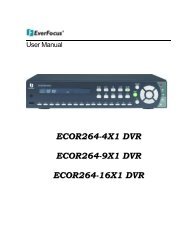
Instruction Manual<br />
<strong>EDR810H</strong>/<strong>EDR810M</strong><br />
<strong>EDR410H</strong>/<strong>EDR410M</strong><br />
Volume<br />
1
E V E R F O C U S E L E C T R O N I C S C O R P O R A T I O N<br />
EDR 810H/810M/410H/410M<br />
Instruction Guide<br />
2005 <strong>EverFocus</strong> Electronics Corp<br />
www.everfocus.com<br />
All rights reserved. No part of the contents of this manual may be reproduced or transmitted in any form or by any means<br />
without written permission of the Everfocus Electronics Corporation.<br />
Release Date: April 2009<br />
QuickTime is a registered trademark of the Apple Computer, Inc.<br />
Windows is a registered trademark of the Microsoft Corporation.<br />
Linksys is a registered trademark of the Linksys Corporation.<br />
D-Link is a registered trademark of the D-Link Corporation.<br />
DynDNS is a registered trademark of the DynDNS.org Corporation.<br />
Other product and company names mentioned herein may be the trademarks of their respective owners.
Federal Communication Commission Interference Statement<br />
This equipment has been tested and found to comply with the limits for a Class B digital device,<br />
pursuant to Part 15 of the FCC Rules. These limits are designed to provide reasonable protection<br />
against harmful interference in a residential installation. This equipment generates, uses and can<br />
radiate radio frequency energy and, if not installed and used in accordance with the instructions,<br />
may cause harmful interference to radio communications. However, there is no guarantee that<br />
interference will not occur in a particular installation. If this equipment does cause harmful<br />
interference to radio or television reception, which can be determined by turning the equipment off<br />
and on, the user is encouraged to try to correct the interference by one of the following measures :<br />
Reorient or relocate the receiving antenna.<br />
Increase the separation between the equipment and receiver.<br />
Connect the equipment into an outlet on a circuit different from that to which the receiver is<br />
connected.<br />
Consult the dealer or an experienced radio/TV technician for help. FCC Caution: Any changes<br />
or modifications not expressly approved by the party responsible for compliance could void the<br />
users’s authority to operate this equipment. This device complies with Part 15 of the FCC Rules.<br />
Operation is subject to the following two conditions: (1) This device may not cause harmful<br />
interference, and (2) this device must accept any interference received, including interference that<br />
may cause undesired operation. This device and its antenna(s) must not be co-located or operating<br />
in conjunction with any other antenna or transmitter.
TABLE OF CONTENTS<br />
1. PRODUCT OVERVIEW....................................................................................................... 12<br />
1.1 FEATURES ............................................................................................................................ 12<br />
1.2 SPECIFICATIONS ................................................................................................................... 13<br />
1.3 FRONT PANEL KEYPADS....................................................................................................... 14<br />
1.4 BACK PANEL CONNECTIONS ................................................................................................ 17<br />
1.5 MONITOR DISPLAY .............................................................................................................. 20<br />
2. INSTALLATION.................................................................................................................... 24<br />
2.1 BASIC WIRING INSTRUCTIONS ............................................................................................. 25<br />
2.2 HARD DISK DRIVE INSTALLATION ....................................................................................... 27<br />
2.3 FINAL INSTALL PROCESS...................................................................................................... 27<br />
2.4 QUICK INSTALLATION GUIDE FOR <strong>EDR810M</strong> & <strong>EDR410M</strong> ONLY......................... 28<br />
3. DVR MENU SETUP .............................................................................................................. 33<br />
3.1 TIME/DATE SETUP MENU..................................................................................................... 34<br />
3.2 CAMERA SETUP MENU......................................................................................................... 38<br />
3.3 RECORD SETUP MENU ......................................................................................................... 42<br />
3.4 ALARM SETUP MENU........................................................................................................... 44<br />
3.5 MOTION SETUP MENU ......................................................................................................... 47<br />
3.6 VIDEOLOSS SETUP MENU................................................................................................. 50<br />
3.7 NETWORK SETUP MENU ...................................................................................................... 52<br />
3.7.1 CONFIG .............................................................................................................................. 52<br />
3.7.2 ALARM NETWORK .......................................................................................................... 55<br />
3.7.3 EMAIL................................................................................................................................. 56<br />
3.7.4 PASSWORD........................................................................................................................ 57<br />
3.7.5 WIRELESS.......................................................................................................................... 58<br />
3.7.6 PPPOE.................................................................................................................................. 60<br />
3.7.7 DDNS .................................................................................................................................. 61<br />
3.7.8 GPS...................................................................................................................................... 63<br />
3.8 SCHEDULE SETUP MENU...................................................................................................... 64<br />
3.9 DISK SETUP MENU............................................................................................................... 66<br />
3.10 CONTROL SETUP MENU ..................................................................................................... 68<br />
3.11 WARNING SETUP MENU ..................................................................................................... 70<br />
3.11.1 FAN FAULT....................................................................................................................... 70<br />
3.11.2 HDD TEMP ....................................................................................................................... 71<br />
3.11.3 NO HDD............................................................................................................................. 73<br />
3.11.4 HDD FULL ........................................................................................................................ 74<br />
3.12 SYSTEM SETUP MENU........................................................................................................ 76<br />
4. RECORDING OVERVIEW.................................................................................................. 79<br />
4.1 INSTANT (N) RECORDING SETUP.......................................................................................... 79
4.2 SCHEDULE RECORDING SETUP............................................................................................. 80<br />
4.3 EVENT RECORDING SETUP................................................................................................... 81<br />
5. PLAYBACK OVERVIEW..................................................................................................... 84<br />
5.1 BASIC PLAYBACK ................................................................................................................ 84<br />
5.2 SEARCH PLAYBACK ............................................................................................................. 87<br />
6. COPYING VIDEO ................................................................................................................. 90<br />
6.1 VIEWING A COPIED FILE ...................................................................................................... 92<br />
7. CALL OVERVIEW................................................................................................................ 93<br />
8. SCREEN DISPLAY SETTING & MODE ........................................................................... 94<br />
8.1 MODE BUTTON .................................................................................................................... 95<br />
9. UPGRADE FIRMWARE....................................................................................................... 96<br />
10. NETWORKING OVERVIEW............................................................................................ 97<br />
10.1 INTRODUCTION TO TCP/IP................................................................................................. 97<br />
10.2 SUBNET MASKS ................................................................................................................. 97<br />
10.3 GATEWAY ADDRESS ........................................................................................................... 98<br />
10.4 VIRTUAL PORTS ................................................................................................................. 98<br />
10.5 PRE-INSTALLATION ............................................................................................................ 98<br />
10.6 WHAT TYPE OF NETWORK CONNECTION DO YOU HAVE?.................................................. 100<br />
10.7 SIMPLE ONE TO ONE CONNECTION .................................................................................. 101<br />
10.8 DIRECT HIGH SPEED MODEM CONNECTION..................................................................... 107<br />
10.9 ROUTER OR LAN CONNECTION ....................................................................................... 109<br />
11. LINKSYS PORT FORWARDING.....................................................................................112<br />
12. D-LINK PORT FORWARDING........................................................................................116<br />
13. EVERFOCUS DDNS SETUP............................................................................................ 120<br />
14. VIEWING THROUGH INTERNET EXPLORER......................................................... 122<br />
14.1 SEARCH......................................................................................................................... 128<br />
14.1.1 SEARCH BY TIME .............................................................................................................. 128<br />
14.1.2 SEARCH BY EVENT ......................................................................................................... 129<br />
14.2 PTZ CONTROL.................................................................................................................. 130<br />
14.3 REMOTE ARCHIVE...................................................................................................... 131<br />
14.4 REMOTE CONFIGURATION................................................................................................ 136<br />
15. INTERFACE SPECIFICATIONS .................................................................................... 143<br />
15.1 TRANSMISSION SETTING .................................................................................................. 143<br />
15.2 REMOTE CONTROL PROTOCOL......................................................................................... 144
APPENDIX A: REMOTE CONTROL .................................................................................. 147<br />
APPENDIX B: ALARM BOARD CONFIGURATION........................................................ 148<br />
TROUBLESHOOTING........................................................................................................... 150
Safety Warning<br />
WARNING<br />
TO REDUCE RISK OF FIRE OR ELECTRIC SHOCK,<br />
DO NOT EXPOSE THIS APPLIANCE TO RAIN OR MOISTURE.<br />
Press the STOP key to stop playing back.<br />
CAUTION<br />
DO NOT REMOVE COVER. NO USER SERVICEABLE PARTS<br />
INSIDE.<br />
REFER SERVICING TO QUALIFIED SERVICE PERSONNEL.<br />
Note:<br />
This equipment has been tested and found to comply with the limits<br />
for a Class A digital device,<br />
The changes or modifications not expressly approved by the party<br />
responsible for compliance could void the user's authority to operate<br />
the equipment.<br />
Note:<br />
This is a class A product. In a domestic environment this product may<br />
cause radio interference, in which case the user may be required to<br />
take adequate measures.<br />
Notice:<br />
The information in this manual was current when published.<br />
The manufacturer reserves the right to revise and improve its<br />
products.<br />
All specifications are therefore subject to change without notice.
Safety Precautions<br />
Refer all work related to the installation of this product to qualified service<br />
personnel or system installers.<br />
Do not block the ventilation opening or slots on the cover.<br />
Do not drop metallic parts through slots. This could permanently damage the<br />
appliance. Turn the power off immediately and contact qualified service<br />
personnel for service.<br />
Do not attempt to disassemble the appliance. To prevent electric shock, do not<br />
remove screws or covers. There are no user-serviceable parts inside. Contact<br />
qualified service personnel for maintenance. Handle the appliance with care.<br />
Do not strike or shake, as this may damage the appliance.<br />
Do not expose the appliance to water or moisture, not try to operate it in wet<br />
areas. Do take immediate action if the appliance becomes wet. Turn the power<br />
off and refer servicing to qualified service personnel. Moisture may damage<br />
the appliance and also cause electric shock.<br />
Do not use strong or abrasive detergents when cleaning the appliance body.<br />
Use a dry cloth to clean the appliance when it is dirty. When the dirt is hard to<br />
remove, use a mild detergent and wipe gently.<br />
Do not overload outlets and extension cords as this may result in a risk of fire<br />
or electric shock.<br />
Do not operate the appliance beyond its specified temperature, humidity or<br />
power source ratings. Do not use the appliance in an extreme environment<br />
where high temperature or high humidity exists. Use the appliance at<br />
temperature within indoor type DVR for 32 o F ~ +104 o F and a humidity below<br />
90%. The input power source for this appliance is AC100~240V.
Safety Precautions<br />
Read Instruction<br />
All the safety and operating instructions should be read before the unit is<br />
operated.<br />
Retain Instructions<br />
The safety and operating instructions should be retained for future reference.<br />
Heed Warnings<br />
All warnings on the unit and in the operating instructions should be adhered to.<br />
Follow Instructions<br />
All operating and use instructions should be followed.<br />
Cleaning<br />
Unplug the unit from the outlet before cleaning. Do not use liquid cleaners or<br />
aerosol cleaners. Use a damp cloth for cleaning<br />
Attachments<br />
Do not use attachment not recommended by the product manufacturer as they<br />
may cause hazards.<br />
Water and Moisture<br />
Do not use this unit near water-for example, near a bath tub, wash bowl, kitchen<br />
sink, or laundry tub, in a wet basement, near a swimming pool, in an unprotected<br />
outdoor installation, or any area which is classified as a wet location.<br />
Servicing<br />
Do not attempt to service this unit by yourself as opening or removing covers<br />
may expose you to dangerous voltage or other hazards. Refer all servicing to<br />
qualified service personnel.<br />
Power Cord Protection<br />
Power supply cords should be routed so that they are not likely to be walked on<br />
or pinched by items placed upon or against them, playing particular attention to<br />
cords and plugs, convenience receptacles, and the point where they exit from<br />
the appliance.<br />
Object and Liquid Entry<br />
Never push objects of any kind into this unit through openings as they may touch<br />
dangerous voltage points or short-out parts that could result in a fire or electric<br />
shock. Never spill liquid of any kind on the unit.
1. Product Overview<br />
Chapter<br />
1<br />
EDR810/410 DVRs are the industry’s first full-featured digital video recorder designed specifically for<br />
use within the security industry. EDR810/410 DVRs incorporates all the benefits of digital video<br />
recording, is simple to install, and operates just like a VCR. Highly efficient compression technology<br />
and superior resolution of recorded images make the Digital Video Recorder stand out from the<br />
competition as the best choice for security surveillance.<br />
1.1 Features<br />
Duplex Operation for Recording & Playback<br />
Built-in MPEG4 Codec with Configurable Quality<br />
Variable Recording Speeds up to 60/50 Images per second for NTSC/PAL<br />
Audio Recording Capabilities<br />
Motion Detection Capabilities<br />
One 3.5” Hard Disk with Hot-Swap Tray for Internal Storage<br />
Ethernet Interface for Remote Network Viewing<br />
Optional Wireless LAN Interface for Data Transmission<br />
RS485 for Remote Control<br />
Shuttle/Jog Dial for Picture-by-Picture or Fast/Slow Viewing<br />
Easy-to-use Control Panel with Common VCR and Multiplexer Functions<br />
On-Screen Menus Operations with Multi-Language Support<br />
Real-Time Live Display for all Cameras<br />
Easy archiving of video and Remote Viewer through USB port<br />
Remote configuration function<br />
Remote Firmware Upgrade function<br />
Motion detection function can be scheduled according to user’s setting<br />
For mobile models (ED810M/410M), GPS data can be sent out to receiver, for user to orientate<br />
the exact position
1.2 Specifications<br />
Video format NTSC or PAL<br />
Video input 4/8 camera inputs (BNC), 1Vp-p/75ohm<br />
1 BNC video out (1Vp-p/75ohm) for Main Monitor<br />
Video output 1 BNC video out (1Vp-p/75ohm) for Call Monitor<br />
4 BNC outputs (1Vp-p/75ohm) for Looping (4 Channels only)<br />
Video compression MPEG4<br />
720x240, 720x480 or 360x240 for NTSC<br />
Recording resolution<br />
720x288, 720x576 or 360x288 for PAL<br />
Video display<br />
Full, 4, 7, and 9 screen view for Live and Playback<br />
PIP and 2x2 Zoom for Playback only<br />
Alarm inputs 4/8 Alarm Inputs<br />
Alarm outputs 1 Alarm Output<br />
Hard disk storage<br />
One Hot-Swappable 3.5” IDE or SATA Hard Disk<br />
(2.5” hard disk available for mobile models)<br />
Recording rate Up to 120/100 Images per second for NTSC/PAL<br />
Recording mode Continuous, Schedule, Event (Motion and Alarm) recording<br />
Playback rate Up to 60/50 Images per second for NTSC/PAL<br />
Playback search By Date/Time or Event (Motion, Video Loss, Alarm)<br />
Playback options Play, Pause, Stop, Fast Fwd, Fast Rev, Slow Fwd, Slow Rev<br />
Motion detection Yes, with configurable detection grid & sensitivity per camera<br />
Video Loss detection Yes<br />
Event Log Yes<br />
Setup Menu Driven On Screen Display<br />
User input device<br />
Front panel keypad with Shuttle/Jog, IR Remote Control,<br />
EKB500 Keyboard (optional)<br />
Timer<br />
Built-in real time clock with Watch Dog function and Auto Time<br />
Synchronization through NTP server<br />
Title 12-characters title for each camera<br />
Ethernet RJ45 connectors for network communication<br />
Archive USB port for flash memory or external DVD drive<br />
RS-232 9-pin female connector for testing purpose only<br />
RS-485 for Keyboard or PTZ connection<br />
Audio 1 set of stereo inputs, 1 set of stereo outputs<br />
Power rate 12~24 VDC<br />
Dimensions<br />
Inches: 11.7 (L) x 8.3 (W) x 3.5 (H)<br />
Millimeters: 296.9 (L) x 211.1 (W) x 88.9 (H)<br />
Weight 4 kg (approximately 8.8 lbs)<br />
Operating<br />
temperature<br />
0 o C ~ 40 o C (32 104
1.3 Front Panel Keypads<br />
Keys:<br />
1 ~ 8 Channel Key: Press FULL+Channel Key (CH1~CH8) to display video image in the full<br />
screen format; the picture of the corresponding channel will fill the whole screen.<br />
1 CH1 / REC: Press this key to start instant recording.<br />
2 CH2 / REV. PLAY: Reverse Play Back.<br />
3 CH3 / STOP: Press this key to stop recording and playing back.<br />
4 CH4 / PLAY: Play Back.<br />
5 CH5 / PAUSE: Press this key to pause the playback picture.<br />
6 CH6 / SEARCH: Press this key to enter the SEARCH MENU.<br />
7 CH 7 / COPY: Press this key to enter the COPY MENU. If pressed while in playback mode, it<br />
is also used to bookmark copy time.<br />
8 CH8 / ENTER: Press this key to enter items, or jump to next subentry in the menu setting.
9 FULL: Press this key and channel Key at the same time to switch to full screen in both live<br />
mode and play back mode. Press “MODE” to exit full screen.<br />
10 MODE: Switch PIP (Live only), 4, 7 and 9 displays in Live and Playback modes.<br />
11 ZOOM: In full screen mode, 2x electronic zoom. Zoom screen can be moved through JOG.<br />
ENTER key changes the direction. Press the zoom key again to switch the electronic zoom off.<br />
In multiscreen mode: Screen adjustment. Use the JOG to adjust the image to the fit the monitor.<br />
ENTER switches between horizontal and vertical adjustment. Press the zoom key again to switch<br />
the screen adjustment off.<br />
12 SEQ: Press this key to enter the auto sequential switching mode.<br />
13 SELECT: In multi-screen, press this key to assign cameras to different screens; in single<br />
screen, use it to adjust display properties. In menus, press this key to select certain features.<br />
14 CALL: Press this key to enter and set up CALL MENU.<br />
15 DISPLAY: Press this key to switch display of channels and/or status bar.
16 MENU: Press this key to enter or exit MAIN SETUP MENU or to exit from any submenu.<br />
17 HDD Lock: Keeps HDD in place and turns on HDD power.<br />
18 Hard Disk Tray: Hard Disk holder for HDD.<br />
19 Shuttle and Jog Dial<br />
Shuttle:<br />
In the Playback mode, turn the Shuttle dial to fast forward/rewind<br />
the video.<br />
In the Pause mode, turn the Shuttle dial to slow forward/rewind the<br />
video.<br />
In the event list, turn the Shuttle to change pages.<br />
Jog Dial:<br />
In the Menu mode, turn the Jog dial to change settings and values in<br />
subentries. In the Pause mode, turn the Jog dial to forward/rewind<br />
the video frame by frame.<br />
20 USB Slot: USB port allows you to archive video files or upgrade the DVR software.<br />
21 HDD LEDs: LEDs for HDD active power (GREEN) and data reading /writing (YELLOW).<br />
22 Remote Control: Receiver for IR remote control.<br />
23 System LEDs: LEDs for system active LAN, ALARM and POWER display.
1.4 Back Panel Connections<br />
Back panel of 810H Back panel of 810M<br />
Back panel of 410H Back panel of 410M
POWER<br />
1 Main Power plug: Connect the DC 12~ 24V power source to adapter for AC 100~ 240V.<br />
2 Audio IN: Audio input for recording, and it can be set to “YES” or “NO” in the RECORD<br />
SETUP MENU.<br />
Audio OUT: Connect an audio output to a monitor or other device.<br />
MONITOR<br />
3 MAIN MONITOR: This connector is used for the main monitor display, a number of<br />
different display modes may be selected for viewing.<br />
4 CALL MONITOR: This connector is used for the call monitor. This monitor can only<br />
display a full screen picture.<br />
VIDEO CONNECTIONS<br />
5 For EDR810 Series:<br />
VIDEO IN(1~8): BNC video inputs.<br />
For EDR410 Series:<br />
VIDEO IN(1~4): BNC video inputs<br />
VIDEO OUT(1~4): BNC loop-through outputs<br />
ALARM INPUT/OUTPUT<br />
6 ALM-INPUT: Normal open or normal close type alarm signal inputs.<br />
The Alarm Input can be selected as Normal Open (N.O.), Normal Close (N.C.), N.C. TRANS.,<br />
or N.O, TRANS input in the ALARM SETUP MENU.<br />
When an alarm occurs, alarm recording will automatically start.<br />
ALM-OUTPUT: A built-in relay offers 3 nodes which are ALM-COM (common), ALM-NO<br />
(normal open) and ALM-NC (normal close) for external use. Note: Please check APPENDIX<br />
C to see other available alarm input/output functions.
LAN<br />
7 LAN Connector: RJ-45 network connection.<br />
RS232<br />
8 RS232 connector: D-Sub 9-pin connector to RS232 ports for testing purpose ONLY.<br />
RS485<br />
9 RS485 connector: RJ 45 Connector to cascade/control multi Digital Video Recorders.<br />
Remote<br />
10 Remote Control: Remote control port allows for an extension wire with an IR receiver instead<br />
of the IR receiver on the front panel.<br />
Note: The IR receiver extension line (10m) must be purchased separately.<br />
Wireless LAN<br />
11 Antenna: Integrated IEEE 802.11b/g wireless LAN capabilities. The antenna port is for<br />
wireless network antenna use (For EDR 410M and 810M only).<br />
Fan<br />
12 Fan: Cooling fan.
2. Event sign<br />
1.5 Monitor Display<br />
The status information of the cameras or machine will show up, and be located at different places<br />
on the screen.<br />
For mobile model only:<br />
6. GPS<br />
orientation<br />
1. Channel tag<br />
3. Select sign<br />
4. Play status bar<br />
5. Record status bar
1 Channel tag: A channel tag indicates the channel name of the screen.<br />
2 Event sign: Event signals which are small icons with a capital letter and red background show<br />
the events on each screen. There are a total of 6 different signals:<br />
A<br />
M<br />
V<br />
S<br />
Alarm event.<br />
Alarm event shows on a channel if an ALARM is enabled for that camera in the ALARM<br />
SETUP MENU and an alarm is triggered.<br />
Motion event.<br />
Motion event only shows up when the camera’s MOTION is enabled in MOTION SETUP<br />
MENU and the camera detects movement.<br />
Video loss event.<br />
Video loss event only shows when the camera’s VIDEOLOSS is enabled in VIDEOLOSS<br />
SETUP MENU and the camera signal is lost.<br />
Sequence sign.<br />
Sequence sign shows up when the display is in sequence mode.<br />
The last display on the screen has a “*” sign in the top-middle. The S<br />
sign will replace the “*” in<br />
the display when sequence occurs.<br />
Note: Sequence cannot be activated when the multi-screen display is showing all cameras.<br />
T<br />
F<br />
Temperature indication.<br />
This shows if the hard drive’s temperature is overheated.<br />
Overheat temperature is determined in HDD TEMPERATURE of WARNING SETUP<br />
MENU.<br />
Fan fail indication.<br />
This shows when the fan fails to work normally. If you get this warning, contact technical<br />
support for assistance.<br />
3 Select sign: You can assign a camera to a display by pressing SELECT key in live mode.<br />
Dial Jog to move the select sign to the display you would like to change, and then press the desired<br />
channel key from the front panel to move that channel to that screen. Press SELECT again to exit<br />
from this mode.<br />
4 Play status bar: The play status bar appears in play back mode if the status bar is enabled (see<br />
DISPLAY, 8 th item of Front Panel Keypads). There are three parts that will be shown: play date,<br />
play status, and play time.
Play Date Play Status Play Time<br />
1. Play date<br />
The date on which the video was recorded.<br />
2. Play status<br />
“PAUSE”, when the video playback is paused.<br />
“P## >” means normal play speed on the displayed disk number;<br />
“P## > x N” means N time fast play speed;<br />
“
3. Event<br />
The current/last event that occurred.<br />
4. Current time<br />
The current time, which can be set in the TIME/DATE SETUP MENU.<br />
5. HDD/FAN status<br />
“No Disk”: only shows when no disk is installed or detected.<br />
“No Fan”: only shows when internal fan stops working.<br />
“HDD OT”: only shows if hard drive is over temperature.<br />
6 GPS orientation<br />
When GPS data is sent out to receiver, the exact position will be located by showing vehicle’s<br />
longitude and latitude.
2. Installation<br />
The installations described below should be done by qualified service personnel or system<br />
installers.<br />
I) PACKING<br />
Please check accessories in the packing before the installation.<br />
II) SYSTEM FLOORPLAN<br />
Please refer to the following diagrams for the system connections.<br />
Note: Monitor and Camera must be purchased separately.<br />
Diagram 2.1<br />
Chapter<br />
2
2.1 Basic Wiring Instructions<br />
Please refer to diagram 2.1 to assist you with this portion of the installation.<br />
1. Power<br />
Connect the power source or adapter into the power socket.<br />
2. Cameras<br />
Connect each cameras video output to the video inputs on the digital video recorder.<br />
Note: At least one camera must be connected before the system is running for the auto detection of<br />
video standard to take effect.<br />
3. Audio Input<br />
The camera audio output or Microphone is connected to the audio input terminal at the rear panel.<br />
4. Audio Output<br />
Connect the speaker or other audio listening devices to the audio output terminal on the back of the<br />
digital video recorder.<br />
5. Ethernet<br />
The digital video recorder may be viewed from a PC via the LAN connector using a RJ45 Ethernet<br />
cable.<br />
6. RS485<br />
The digital video recorder can be controlled from an EKB500 keyboard via RS485.<br />
Note: This can be done using a RJ45-to-serial cable.<br />
7. Main Monitor<br />
Connect a monitor to the main monitor output connector. The main monitor displays live or<br />
recorded cameras in any available format.<br />
Note: The main monitor must be connected in order to make configuration changes, enter the main<br />
menu, or do a playback at the machine.
8. Call Monitors<br />
Connect the call monitor output connectors to a call monitor. The call monitor display selected live<br />
cameras in full screen format.<br />
Note: The call monitor will only display one full screen camera at a time.
2.2 Hard Disk Drive Installation<br />
The first step in installing the hard drive is to insert the hard drive sleeve into the machine. The hard<br />
disk drive default setting is initially set to master. The second step is to insert the key provided and turn<br />
the tray key to the lock position. If this process is ignored the hard disk drive will not be detected.<br />
Note: If the Hard Disk Drive is not locked in with the key, HDD LED will not light<br />
up and the DVR will not go into record mode. This is because the Hard Drive is<br />
not being recognized.<br />
Note: After powering on the DVR, it will start to load system. It takes a while to<br />
complete loading system, during this time, please do not install or remove the hard<br />
disk. No action is recommended while the machine is loading system.<br />
Diagram 2.2 shows 3.5“ Hard Drive<br />
2.3 Final Install Process<br />
Once you have completed the basic wiring installation and the hard disk drive installation you are ready<br />
to turn on the DVR. Simply plug the power source you installed earlier. The POWER LED lights will<br />
light up if power is normal. The next step is to set up the menu options for the DVR.
2.4 QUICK INSTALLATION GUIDE FOR <strong>EDR810M</strong> & <strong>EDR410M</strong><br />
ONLY<br />
The <strong>EDR810M</strong> & <strong>EDR410M</strong> are the full-featured digital video recorders designed specifically<br />
for use in mobile applications. Please refer to the following Quick Installation Guide for installing<br />
<strong>EDR810M</strong> or <strong>EDR410M</strong> into mobile applications such as buses, cars and police cruisers.<br />
The DVR can be mounted horizontally (suspend or support mounted).<br />
Support<br />
<strong>EDR410M</strong><br />
Interface<br />
Show all the possible ways to mount the DVR.<br />
Use the two Z-brackets supplied to mount it in any ways shown.<br />
Quick Installation Guide<br />
EDSR40<br />
0M<br />
Support<br />
EDSR400M<br />
Suspend<br />
Interface<br />
<strong>EDR410M</strong><br />
Suspend
Unpack Everything<br />
Make sure you have everything you need before you begin the installation.<br />
Equipment Required<br />
The following tools may help you to complete the installation:<br />
Drill<br />
Screwdrivers<br />
Wire cutters<br />
Choosing the Location Choose a location for installation that:<br />
Provides convenient access for installing or removing the hard drive<br />
Allows air to flow around the fan vents. Inadequate or improper air flow can impede proper<br />
operation of the unit<br />
Avoid any location for installation:<br />
That is subject to high vibration<br />
That is subject to high sunlight levels<br />
That is subject to drenched of the rain<br />
Where passengers can interfere with unit<br />
Next to a heater duct<br />
The following table lists the recommended location options.<br />
Location Convenient operation Easy to install Low vibration Good air flow<br />
Bottom of glove box- horizontal mount<br />
Bottom of passenger seat next to the driver<br />
Underneath bulkhead-horizontal mount<br />
Front of bulkhead-horizontal mount<br />
Beside deriver seat-horizontal mount<br />
Yes<br />
NO<br />
Yes<br />
Yes<br />
Yes<br />
Caution: Do not install the DVR on the floor or on the transmission access hatch. These<br />
locations have the highest levels of vibration and may be subject to water damage.<br />
Yes<br />
Yes<br />
Yes<br />
Yes<br />
Yes<br />
Yes Yes<br />
Yes<br />
NO<br />
Yes<br />
Yes<br />
Yes<br />
Yes<br />
Yes<br />
Yes
Possible Installation Locations Inside the Automobile Vehicle: Truck<br />
Glove box (inside or underneath)<br />
Drive seat (between seat and wall) or Passenger seat (underneath)<br />
(Users are suggested to use “support” for mounting option)<br />
Show the wiring on the wiring harness that connects to the electrical system.<br />
(5 A)<br />
(24 V)
Possible Installation Locations Inside the Automobile Vehicle: TOYOTA CAMRY<br />
Glove box (inside or underneath)<br />
Drive seat (between seat and wall)<br />
Trunk (Users are suggested to use<br />
“suspend” for mounting option)<br />
Passenger seat (underneath)<br />
Show the wiring on the wiring harness that connects to the electrical system.
Installing the Camera(s) and Monitor<br />
The DVR is typically connected to one camera installed inside the car. Other camera(s) can also<br />
be installed in different locations (for example, use the waterproof camera to the outside of<br />
vehicle). For installation procedure, please refer to the guide that came with the camera(s) you<br />
purchased.<br />
The Monitor power supply connects from the Automotive adapter (cigarette plug)<br />
Monitor and cameras must be purchased separately.<br />
LCD Monitor<br />
LCD Monitor<br />
Connect the Camera(s)Connect the power connector from the camera(s) harness into the<br />
CAMERA POWER OUT jack on the back panel of the DVR.<br />
Connect the primary camera(s) video connector to the CAMERA INPUT and the audio connector<br />
to the AUDIO INPUT in the back panel.<br />
Adjust the camera(s). After the camera is installed, connect a monitor directly to the camera and<br />
observe the image.<br />
Make any adjustment if necessary.
3. DVR Menu Setup<br />
Assuming you have completed the first two chapters of this manual, you are now ready to begin setting<br />
up the digital video recorder. The following chapter will walk you through the detailed DVR Menu step<br />
by step and how to set the DVR for your specific application. To begin this process, press the MENU<br />
key. Once inside the Main Menu you will find there are 12 setup option pages as follows.<br />
MENU<br />
Press the MENU key to enter or exit the MAIN SETUP MENU.<br />
Press the MENU key in any sub-menu to go back to previous screen.<br />
Dial the Jog clockwise or counterclockwise to scroll through the MAIN MENU<br />
options or to change subentry values.<br />
Press the ENTER key to go to the next subentry in a menu setting.<br />
Press the DISPLAY key to go to the previous subentry in a menu setting.<br />
Diagram 3.1<br />
Chapter<br />
3
3.1 Time/Date Setup Menu<br />
Diagram 3.2<br />
Diagram 3.2 is a screenshot of the TIME/DATE SETUP MENU. This menu is used to set up the<br />
correct time and date for your region of the world. You are able to setup daylight savings as well as<br />
synch it with an internet based time server. In the TIME/DATE SETUP MENU the following fields<br />
are defined as follows:<br />
1. TIME FORMAT: This field represents the time format on the DVR. You can select between 12<br />
HOUR and 24 HOUR format.<br />
2. TIME: This field represents the current time on the DVR. To change this, turn the Jog Dial on the<br />
DVR.<br />
The Time is represented as follows:<br />
Hour: 00~23 (1 ~ 12 if TIME FORMAT is 12 HOUR): Minute: 00~59: Second: 00~59<br />
3. DATE FORMAT: This field represents the date format on the DVR. To change this, simply use<br />
the Jog Dial on the DVR. There are three date formats to select from: YYYY-MM-DD,<br />
MM-DD-YYYY and DD-MM-YYYY.<br />
4. DATE: This field represents the date on the DVR. To change this, turn the Jog Dial on the DVR.<br />
The day of the week automatically adjusts according to the other settings.<br />
By default, the date is represented as follows:<br />
Year: 2000~2037 / Month: 01~12 / Date: 01~31 (Day of Week)
5. DAYLIGHT SAVING: This field represents the daylight savings on the DVR. To change this,<br />
simply use the Jog Dial on the DVR. Select “ON” or “OFF” to enable or disable daylight saving<br />
time function. This feature must be disabled in order to make any changes to the start and end<br />
times.<br />
6. START TIME: To set the beginning of daylight saving time.<br />
To set the start month of daylight saving time: Dial the jog to set the start month.<br />
JAN FEB MAR APR MAY JUN<br />
JUL<br />
AUG<br />
SEP<br />
OCT<br />
To set the start week of daylight saving time: Dial the jog to set the start week.<br />
1 ST 2 ND 3 RD 4 TH<br />
To set the start date of daylight saving time: Dial the jog to set the start date.<br />
To set the starting time change of daylight saving time: Choose the “FROM” time and<br />
“TO” time when daylight savings starts.<br />
7. END TIME: To set the end of daylight saving.<br />
To set the end month of daylight saving time: Dial the jog to set the end month.<br />
To set the end week of daylight saving time: Dial the jog to set the end week.<br />
1 ST 2 ND 3 RD 4 TH<br />
LAST<br />
To set the end date of daylight saving time: Dial the jog to set the end date.<br />
NOV<br />
LAST<br />
To set the ending time change of daylight saving time: Choose the “FROM” time and “TO”<br />
time when daylight saving time ends<br />
DEC<br />
SUN MON TUE WED THU FRI SAT<br />
JAN FEB MAR APR MAY JUN<br />
JUL<br />
AUG<br />
SEP<br />
OCT<br />
NOV<br />
DEC<br />
SUN MON TUE WED THU FRI SAT
8. TIME SYNCHRONIZE: Select “ON” or “OFF” to enable or disable time synchronize which<br />
will automatically update the DVR’s time when connected to a network. To change this, simply use<br />
the Jog Dial on the DVR.<br />
9. TIME SERVER: You can set the time server address that the DVR connects to for time<br />
synchronize. To determine the IP address of NTP Server, please follow these steps:<br />
a) Go to a PC that is connected to the internet.<br />
b) Click on “START” -> “RUN” -> type “cmd” and press “OK”.<br />
c) In the Dos Prompt, type “ping pool.ntp.org” to find out the IP address of an NTP Server.<br />
Diagram 3.3<br />
9. TIME ZONE: You can set the time zone that the DVR adjusts to when updating from the time<br />
server.<br />
Atlantic Daylight Time subtract 3 hours from GMT<br />
Atlantic Standard Time subtract 4 hours from GMT<br />
Eastern Daylight Time subtract 4 hours from GMT<br />
Eastern Standard Time subtract 5 hours from GMT<br />
Central Daylight Time subtract 5 hours from GMT<br />
Central Standard Time subtract 6 hours from GMT<br />
Mountain Daylight Time subtract 6 hours from GMT<br />
Mountain Standard Time subtract 7 hours from GMT<br />
Pacific Daylight Time subtract 7 hours from GMT<br />
Pacific Standard Time subtract 8 hours from GMT<br />
Alaska Daylight Time subtract 8 hours from GMT
Alaska Standard Time subtract 9 hours from GMT<br />
Hawaii-Aleutian Daylight Time subtract 9 hours from GMT<br />
Hawaii-Aleutian Standard Time subtract 10 hours from GMT<br />
11. TIME UPDATE BY: Once you enable the TIME SYNCHRONIZE, you can select the<br />
synchronization frequency by:<br />
DAY WEEK<br />
MONTH
3.2 Camera Setup Menu<br />
Diagram 3.4<br />
Diagram 3.4 is a screen shot of the CAMERA SETUP MENU. This menu will walk you through<br />
setting up the Camera Recording Speeds, Camera Titles, PTZ ID, covert modes, and recording quality.<br />
In the CAMERA SETUP MENU the following fields are defined as:<br />
1. TITLE: The title setting allows you to assign a title to each camera input. Each channel supports a<br />
title with up to 12 characters. Press Enter to move to each character and use the Jog Dial to change<br />
the value. The available alphanumeric characters are:<br />
0,1,2,3,4,5,6,7,8,9,<br />
A,B,C,D,E,F,G,H,I,J,K,L,M,N,O,P,Q,R,S,T,U,V,W,X,Y,Z,<br />
( ) . , + - / and an empty space.<br />
2. PTZ ID: Select PTZ ID/Address from 001~255 or OFF. OFF is the same as 000. The default value<br />
is 10+N where N is camera’s number. This ID must be the same as the ID used in PTZ Dip Switch.<br />
To change this, simply use the Jog Dial on the DVR.<br />
3. INSTALL/COVERT: Select “ON” to enable a camera, and “OFF” to disable it. All recording<br />
must be stopped before making changes to INSTALL. To take full advantage of the DVR’s<br />
recording ability, switch any unused Camera Ports to OFF in this section. For COVERT, select<br />
“ON” to cover a camera, and disable the screen in live mode. However, the image is still recorded,<br />
and can be played back by any user that has playback right. The covert channels will not show up<br />
in the sequence mode. To make changes, simply use the Jog Dial on the DVR.
4. SEQ (MAIN/CALL): Set the number of seconds a camera is displayed in sequence. The first<br />
number is for sequence on the Main Monitor, the second number is for sequence on Call Monitor.<br />
5. REC QUALITY: Select an image quality for recording. There are six different qualities available.<br />
A higher image quality uses more HDD space. To change this, simply use the Jog Dial on the<br />
DVR. The approximate space needed per second is listed below:<br />
720x480 Video Source<br />
Simple: Complex:<br />
Average size<br />
per image<br />
LOWER: 8.04KB 12.33KB<br />
LOW: 8.42KB 13.7KB<br />
BASIC: 10.15KB 16.72KB<br />
STANDARD: 11.86KB 19.56KB<br />
HIGH: 14.72KB 24.63KB<br />
SUPERIOR: 18.60KB 30.05KB<br />
720x240 Video Source<br />
Simple: Complex:<br />
Average size<br />
per image<br />
LOWER: 3.53KB 7.82KB<br />
LOW: 3.87KB 8.36KB<br />
BASIC: 4.21KB 8.9KB<br />
STANDARD: 4.92KB 9.54KB<br />
HIGH: 5.62KB 10.17KB<br />
SUPERIOR: 6.41KB 12.89KB<br />
360x240 Video Source<br />
Simple: Complex:<br />
Average size<br />
per image<br />
LOWER: 1.76KB 4.56KB<br />
LOW: 1.87KB 4.87KB<br />
BASIC: 1.97KB 5.46KB<br />
STANDARD: 2.38KB 6.51KB<br />
HIGH: 2.67KB 7.08KB<br />
SUPERIOR: 3.63KB 9.02KB<br />
Note: “Simple” refers to very few changes occurring during recording; “Complex” means the<br />
whole image is constantly changing. Since the compression ratio of MPEG4 fully depends on the<br />
variation and complexity of the recorded video, the table above is for reference only.
6. REC SPEED & ACTION:<br />
TP: Scheduled recording time 1~8 which can be set in the SCHEDULE SETUP MENU. “N” is<br />
the normal recording time, which is activated by pressing the Record button. If you have set a Time<br />
Period in Schedule Setup Menu, then there will be a star sign (*) beside that TP in Camera Setup<br />
Menu.<br />
NORMAL: Normal record speed up to 15 IPS (images per second). The default normal record<br />
speed is 1 IPS. EDR810/410 will adjust to the maximum recording speed by calculating the total<br />
installed cameras that have been enabled in the CAMERA SETUP MENU.<br />
EVENT: Event record speed (Images per second) up to 30 IPS or “OFF”.<br />
Note: In order to activate a new record speed, you need to disable all current record actions and<br />
then turn them back on.<br />
ACTION<br />
Set “ON” to activate motion action on a selected Time Period.<br />
Set “OFF” to disable motion action on a selected Time Period.<br />
This setting correlates closely with Motion Setup. If motion setting is disabled, motion detection<br />
will not function regardless if TP (Time Period) Action in Camera Setup Menu is ON or OFF.<br />
However, if Motion setting is enabled, then motion detection function works depending on<br />
Action setting in Camera Setup Menu. All motion actions (including buzzer, relay, network alarm,<br />
e-mail and log) will be triggered if they are enabled in Motion Setup Menu as long as Action is<br />
“ON” for the TP (Time Period) you have set. If you do not wish to have motion detected for a<br />
specific time, set Action “OFF” for that Time Period. This function gives you flexibility to set the<br />
motion detection feature ON or OFF for different Time Periods.
7. SUMMARY:<br />
Diagram 3.5<br />
Dial Jog to change items in the SUMMARY table.<br />
All cameras’ statuses are shown in the SUMMARY table. The table is for checking camera overall<br />
statuses only, not for changing them.<br />
Note: The SUMMARY table also exists in ALARM, MOTION and VLOSS SETUP MENU. All of these<br />
SUMMARY tables are also for checking particular overall statuses, not for changing them.<br />
8. Copy camera’s setting from a camera to other cameras: In order to copy the setting from a<br />
camera to other cameras, we provide a setting copy function. Press MENU when you finish setting up a<br />
camera, and then press COPY. The word “COPIED” will show up in the top right corner of the<br />
screen, and it means the settings have been copied. Dial the Jog to the camera you would like to copy<br />
to, and then press SEARCH. The settings of the first camera will be copied to the next one, and<br />
“PASTED” will show up in the top right corner.<br />
NOTE: TITLE, PTZ ID, and INSTALL/COVERT cannot be copied. These 3 options need to be set<br />
independently.
3.3 Record Setup Menu<br />
Diagram 3.6<br />
Diagram 3.6 is a screen shot of the RECORD SETUP MENU. This menu is for setting up the<br />
options for recording. In the RECORD SETUP MENU the following fields are defined as<br />
follows:<br />
1. RECORD AUDIO:<br />
YES: Audio will be recorded when machine is recording and a microphone is connected.<br />
NO: Audio will not be recorded when machine is recording.<br />
2. TIME STAMP:<br />
ON: The time stamp will show on both the live and recorded video.<br />
OFF: The time stamp will not show on the live or recorded video.<br />
3. TIME STAMP POSITION:<br />
BOTTOM: The time stamp will show on the bottom.<br />
TOP: The time stamp will show on the top.
4. WATER MARK:<br />
ON: Recording is overlaid by a visible watermark (“W”).<br />
OFF: No watermark.<br />
5. RESOLUTION: The resolutions for NTSC are 720x480, 720x240 and 360x240; the default<br />
value is 720x240. The resolutions for PAL are 720x576, 720x288 and 360x288; the default value<br />
is 720x288.<br />
NOTE: The resolution determines the maximum record speed supported by the DVR.<br />
NTSC<br />
720x480 = 30 IPS (this IPS value is divided by the amount of cameras installed)<br />
720x240 = 60 IPS (this IPS value is divided by the amount of cameras installed)<br />
360x240 = 120 IPS (this IPS value is divided by the amount of cameras installed)<br />
6. RECORD MODE:<br />
REWRITE: Continue recording. Disk will begin overwriting if it is full.<br />
STOP: Stop recording when disk is full.<br />
7. AUTOWRITE WITHIN: You can set DVR to automatically overwrite after the selected<br />
number of days. If you do not wish to use this function, simply select “0”.<br />
8. PRE-ALARM RECORDING<br />
Select “YES” to enable pre-alarm recording function. Select “NO” to disable pre-alarm recording<br />
function.<br />
9. RELAY OUT<br />
By selecting “1”, user can easily identify whether DVR is recording or not if relay output is<br />
connected to a signaling device. Select “NONE” if you do not wish to identify recording status.
3.4 Alarm Setup Menu<br />
Diagram 3.7<br />
Diagram 3.7 is a screen shot of the ALARM SETUP MENU. An alarm is defined as an electrical,<br />
electronic, or mechanical device that sends an alert by means of a signal. In this case the signal<br />
triggers the recorder to start recording the alarmed event. This menu contains all the alarm operations<br />
and options needed to successfully set up an alarm recording. In the ALARM SETUP MENU the<br />
following fields are defined as:<br />
1. ALARM: This field is to turn alarm recording on or off. The Default from the factory is set to<br />
Enable. To change this, simply use the Jog Dial on the DVR.<br />
ENABLE: Enable alarm detection.<br />
DISABLE: Disable alarm detection.<br />
2. ALARM TYPE: This field is to set the type of alarm connection. The Default from the factory is<br />
set to N.O. To change this, simply use the Jog Dial on the DVR.<br />
N. O.: Normal Open alarm.<br />
N. C.: Normal Close alarm.<br />
N.O. Trans.: When the alarm is triggered, buzzer starts to function no matter how long the alarm<br />
duration is set until you set it back to N.O.<br />
N.C. Trans.: When the alarm is triggered, buzzer starts to function no matter how long the alarm<br />
duration is set until you set it back to N.C.
3. LOG:<br />
ON: Select ON if you wish to record Alarm Events in the Log.<br />
OFF: Select OFF if you do not wish to record Alarm Events in the Log.<br />
4. ACTIVE CAMERA: This field is to activate camera you want to have the alarm enabled too.<br />
For example if you had an external motion detector on camera one you would set this option to<br />
camera one. The Default from the factory is set to on. To change this, simply use the Jog Dial on<br />
the DVR.<br />
Active camera setting, from camera 01~08. You can set the camera which corresponds to<br />
the place where the alarm is located.<br />
Note: The recording camera number in an event depends on the alarm number, and the active<br />
camera images will not be recorded. Example: You assign camera 3 as the active camera to<br />
alarm 1. When the alarm 1 is triggered, camera 3 will be displayed and camera 1 will be<br />
recorded.<br />
5. PTZ PRESET: Select PTZ PRESET from “001” to “255”, so that when Alarm occurs, speed<br />
dome will turn to this preset position for event recording. This function improves surveillance<br />
quality of an alarm event. If you wish to disable this function, please simply select “OFF”.<br />
6. DURATION:<br />
1~99 SEC: The amount of time alarm recording, screen change, buzzer and output contact will<br />
last. Adjustable from 1 ~ 99 seconds.<br />
TRANSPARENT: Continuous recording, screen change, buzzer, and output contact for an alarm<br />
event.<br />
7. ALARM OUTPUT: This will transmit a signal to another device. The setting of alarms are<br />
NONE = not activated, 1 = output signal 1 transmitted.<br />
8. ALARM EMAIL:<br />
YES: Send an email when an alarm occurs.<br />
NO: Do not send an email when an alarm occurs.<br />
The email address and e-mail server can be set in the NETWORK SETUP MENU.<br />
9. BUZZER: Audible alarm buzzer.<br />
ENABLE: To enable an alarm buzzer.<br />
DISABLE: To disable an alarm buzzer.
10. ALARM NETWORK:<br />
YES: Enable alarm network.<br />
NO: Disable alarm network.<br />
11. MAIN MON: Display on a main monitor when an alarm occurs.<br />
NO CHANGE: No change on the display in the main monitor when an alarm occurs.<br />
FULLSCREEN: A full screen of the active camera will display when an alarm occurs.<br />
12. CALL MON: Display on a call monitor when an alarm occurs.<br />
NO CHANGE: No change on the display in the main monitor when an alarm occurs.<br />
CAMERA 1~8: Display the active camera in full screen mode to the call monitor.<br />
13. SUMMARY: Dial Jog to change items in the SUMMARY table. All alarm’s statuses are shown<br />
in SUMMARY tables. These tables are for checking alarm overall statuses, but not for changing<br />
them.<br />
Note: Please check APPENDIX B to see other available alarm input / output functions.
3.5 Motion Setup Menu<br />
Diagram 3.8<br />
Diagram 3.8 is a screen shot of the MOTION SETUP MENU. We define motion as a change of<br />
pixilation in the field of view, which is detected by the digital video recorder, and triggering the<br />
recorder to start recording. Motion is also considered an event. This menu is for setting up the digital<br />
recorder for motion recording on a per camera basis. In the MOTION SETUP MENU the following<br />
fields are defined as follows:<br />
1. MOTION: This field is to turn motion recording on or off. The Default from the factory is set to<br />
off or disabled. To change this, simply use the Jog Dial on the DVR.<br />
ENABLE: Enable motion detection.<br />
DISABLE: Disable motion detection.<br />
Note: Motion only works in live and playback modes. It is invalid while in menus.<br />
2. SENSITIVITY: The sensitivity allows users to adjust to a suitable motion detection sensitivity.<br />
There are 10 sensitivities available; level 1 is the lowest, and level 10 is the highest. The default is 7.<br />
To change this, simply use the Jog Dial on the DVR.<br />
3. LOG:<br />
ON: Select ON if you wish to record Motion Events in the Log.<br />
OFF: Select OFF if you do not wish to record Motion Events in the Log.
4. DURATION: The amount of time a motion event will record - from 1 sec to 99 seconds. The<br />
default value is 5 seconds. To change this, simply use the Jog Dial on the DVR.<br />
5. ALARM OUTPUT: This will transmit a signal to another device. The setting of alarms are<br />
NONE = not activated, 1 = output signal 1 transmitted. To change this, simply use the Jog Dial<br />
on the DVR.<br />
6. ALARM EMAIL:<br />
YES: Send an email when motion occurs.<br />
NO: Do not send an email when motion occurs.<br />
The email address and e-mail server can be set in the NETWORK SETUP MENU.<br />
7. ALARM NETWORK:<br />
YES: Enable alarm network when motion occurs.<br />
NO: Disable alarm network when motion occurs.<br />
8. BUZZER: Audible buzzer when motion is detected.<br />
ENABLE: To enable a motion buzzer.<br />
DISABLE: To disable a motion buzzer.<br />
9. MOTION DELAY:<br />
Select motion delay time from 0~7 level.<br />
10. MAIN MON: Display on a main monitor when an alarm occurs.<br />
NO CHANGE: No change on the display in the main monitor when a motion occurs.<br />
FULLSCREEN: A full screen of the active camera will display when motion occurs.<br />
11. CALL MON: Display on a call monitor when motion occurs.<br />
NO CHANGE: No change on the display in the main monitor when motion occurs.<br />
CAMERA 1~8: Display the active camera in full screen mode to the call monitor.<br />
12. SUMMARY: Dial Jog to scroll through options in the SUMMARY table. All alarm’s statuses<br />
are shown in SUMMARY tables. These tables are for checking alarm overall statuses, but not<br />
for changing them.
To edit a MOTION AREA, enter a desired channel and press SELECT. Motion must be set to<br />
“Enable” in order to edit the motion detection area.<br />
In the motion edit mode:<br />
The default motion area of each camera is entire<br />
screen which displays in light green.<br />
Press COPY to start setting an area.<br />
Use the JOG Dial to move the cursor. Press<br />
ENTER to switch between vertical and<br />
horizontal movement.<br />
Press SEARCH to end and enable the selected<br />
area, or press PAUSE to end and disable the<br />
area.<br />
To quit the motion area edit, press MENU.<br />
To test a motion area: Grids will turn into light red from light green when a motion is<br />
detected.<br />
To clear the motion entire area: Press PLAY to clear the entire motion area.<br />
If you forget the motion grid commands: Press DISPLAY to get a hint window<br />
(shows below) in motion edit mode.<br />
MENU<br />
COPY<br />
ENTER<br />
SEARCH<br />
PAUSE<br />
- EXIT<br />
- SELECT AREA<br />
- CHANGE DIR<br />
- ON AREA<br />
- OFF AREA
3.6 VIDEOLOSS Setup Menu<br />
Diagram 3.9<br />
Diagram 3.9 is a screen shot of the VIDEOLOSS SETUP MENU. VIDEOLOSS event is caused<br />
when no video signal input is detected on a channel. Usually it happens when the camera loses<br />
power or the camera fails. In the VIDEOLOSS SETUP MENU the following fields are defined<br />
as follows:<br />
1. VIDEOLOSS:<br />
ENABLE: Enable video loss detection.<br />
DISABLE: Disable video loss detection.<br />
2. LOG:<br />
ON: Select ON if you wish to record Video Loss Events in the Log.<br />
OFF: Select OFF if you do not wish to record Video Loss Events in the Log.<br />
3. DURATION: The amount of time a Video loss event will record - from 1 sec to 99 seconds. The<br />
default value is 5 seconds. To change this, simply use the Jog Dial on the DVR.<br />
4. ALARM OUTPUT: This will transmit a signal to another device. The setting of alarms are<br />
NONE = not activated, 1 = output signal 1 transmitted. To change this, simply use the Jog Dial<br />
on the DVR.
5. ALARM EMAIL: Select “YES” for sending an email when video loss occurs. The email address<br />
can be set in the NETWORK SETUP MENU.<br />
6. BUZZER: Audible alarm buzzer.<br />
ENABLE: To enable a video loss buzzer.<br />
DISABLE: To disable a video loss buzzer.<br />
7. ALARM NETWORK:<br />
YES: Enable alarm network.<br />
NO: Disable alarm network.<br />
8. SUMMARY: All video loss’s statuses are shown in SUMMARY tables. These tables are for<br />
checking video loss overall statuses, but not for changing them.
3.7 Network Setup Menu<br />
Diagram 3.10<br />
Diagram 3.10 is a screen shot of the NETWORK SETUP MENU. This menu is for setting up the<br />
configurations for networking to the DVR. There are 6 subentries that are CONFIG, ALARM,<br />
EMAIL, PASSWORD, PPPoE and DDNS in the NETWORK SETUP MENU. Mobile units will<br />
also have the WIRELESS and GPS features available. Please refer to the Networking Chapter of this<br />
manual to fully understand how to setup your network for this DVR. In the Network Setting Menu the<br />
following fields are defined as follows:<br />
Note: Since every Network Configuration is different, please contact your Network Administrator<br />
or ISP for details on how to assign those IP addresses and port numbers.<br />
3.7.1 CONFIG<br />
In the CONFIG of the NETWORK SETUP MENU, we define:<br />
1. IP CONFIG:<br />
FIXED IP: User can manually set the IP address for network connection.<br />
DHCP: DHCP server in LAN will automatically provide the IP address for network connection.<br />
When you choose this option, the numbers will be faded out.<br />
PPPoE: This is a DSL connection application. ISP will ask user to input user name and<br />
password. When you choose this option, please configure settings in the PPPoE options first.
2. IP Address<br />
This field shows the current IP Address for the DVR. A Fixed IP address does not change and<br />
must be set manually. To change this, simply use the Jog Dial on the DVR. When DHCP is<br />
selected, DHCP server will assign this value automatically.<br />
Note: The addresses in the machine are for our own testing you should apply your own addresses<br />
to comply with your network. Refer to Networking Chapter for more details.<br />
3. SUBNET MASK<br />
This field is to set the subnet mask for your network so as the DVR will be recognized within the<br />
network. Example: 255.255.255.000. To change this, simply use the Jog Dial on the DVR. When<br />
DHCP is selected, the DHCP server will assign this value automatically.<br />
4. GATEWAY<br />
This field is to set the gateway for your network so the DVR will be recognized within the<br />
network. To change this, simply use the Jog Dial on the DVR. When DHCP is selected, the<br />
DHCP server will assign this value automatically.<br />
5. DNS SERVER<br />
This field is to set the DNS server for your network so the DVR will be recognized within the<br />
network. To change this, simply use the Jog Dial on the DVR. When DHCP is selected, the<br />
DHCP server will assign this value automatically.<br />
6. REMOTE RELAY CONTROL:<br />
YES: By selecting YES, system will accept remote command of relay control.<br />
NO: By selecting NO, system will refuse remote command of relay control.<br />
7. HTTP PORT<br />
The default port number is 80. User can change it to different port number for HTTP/WEB<br />
communication between DVR and client PC.<br />
8. CONTROL PORT<br />
The default port number is 1600. User can change it to different port number for controlling login<br />
between DVR and client PC.<br />
9. DATA PORT<br />
The default data transmitting port number is 37260. User can change it to different port number<br />
for data transfer between DVR and client PC.
Note: If you wish to have multiple users log into the DVR, please open a range of ports on your<br />
router. For example if you want to allow 4 clients to login through the default port 37260, you<br />
should open the port range 37260-37263 on your router.<br />
10. BW CONTROL<br />
This configuration allows user to control the bandwidth of DVR.<br />
11. MAC ADDR<br />
This field is for those Internet service providers or Network administrators who require a MAC<br />
address of the network card of the DVR. This option cannot be changed.
3.7.2 ALARM NETWORK<br />
DVR can send out Alarm message to an Alarm Server. This function is reserved to work with our<br />
Control Management System – PowerCon 4. In the ALARM of the NETWORK SETUP MENU,<br />
we define:<br />
Diagram 3.11<br />
1. PROTOCOL: Select which communication protocol with Alarm servers or Alarm receiving<br />
clients.<br />
TCP: communicate with client via TCP protocol.<br />
UDP: communicate with client via UDP protocol<br />
2. PORT NUMBER: setting the communication port with Alarm server. The default is 1600.<br />
3. UNIQUE ID: setting the ID number of your DVR to Alarm server.<br />
4. SERVER 1: assign the IP address of Alarm server 1.<br />
5. SERVER 2: assign the IP address of Alarm server 2.
3.7.3 EMAIL<br />
In the EMAIL of the NETWORK SETUP MENU, we define:<br />
Diagram 3.12<br />
1. SMTP SERVER<br />
Assign the SMTP (e-mail) server’s name.<br />
Note: For more reliable email service, use the server’s IP address.<br />
2. PORT NUMBER<br />
Assign the port number for SMTP server. The default port is 25.<br />
3. AUTHENTICATION<br />
Select “YES”, if the SMTP server requires Authentication (user name / password)<br />
4. USER<br />
Input the login user ID if the SMTP server requires Authentication.<br />
5. PASSWD<br />
Input the password if the SMTP server requires Authentication.<br />
6. RECEIV. EMAIL ADDR<br />
Input the e-mail address for receiving e-mail messages when the EVENT is enabled and triggered.<br />
Example: In Motion Setup Menu, if the “EMAIL/NETWORK” is set to “YES”, this e-mail address<br />
will receive a message and a still image (in “ARV” format) from the DVR when Motion is<br />
triggered. This “ARV” file can be played back by opening “DVRViewer.exe” which can be<br />
downloaded from the DVR’s Network Viewer or from the Copy Menu.
7. SENDER EMAIL ADDR<br />
Input sender’s e-mail address, so that receiver can recognize the sender when an event message is<br />
sent out.<br />
3.7.4 PASSWORD<br />
In the PASSWORD of the NETWORK SETUP MENU, we define:<br />
Diagram 3.13<br />
Name/Password/Level: This category is to set up the users that will log into the network. Please<br />
remember that this portion of the Network setting menu is set up in column format.<br />
The default User Name = admin<br />
The default Password = 11111111 (only numeric)<br />
There are 3 level types:<br />
1. Admin: User has all the rights including viewing live video, performing a search, playback,<br />
archiving video, controlling the PTZ camera (if one is connected), and remote configuration.<br />
2. Play: User can view live video, playback, and archive, but does not have access to PTZ control<br />
or remote configuration.<br />
3. Live: Allows user only to view live video.
3.7.5 WIRELESS<br />
In the WIRELESS of the NETWORK SETUP MENU, we define:<br />
Diagram 3.14<br />
1. DHCP: Enable or disable the Dynamic Host Communication Protocol.<br />
YES: Enable DHCP service.<br />
NO: Disable DHCP service.<br />
2. IP ADDRESS: Assign an IP address for this unit, for example: 192.168.010.200<br />
When DHCP is YES, the DHCP server will assign this value automatically.<br />
3. SUBNET MASK: Assign a subnet mask of the network for this unit, for example:<br />
255.255.255.0. When DHCP is YES, the DHCP server will assign this value automatically.<br />
4. GATEWAY: Assign a default gateway for this unit, for example: 192.168.010.001<br />
When DHCP is YES, the DHCP server will assign this value automatically.<br />
5. DNS SERVER: Assign a DNS server for this unit, for example: 168.195.001.001<br />
When DHCP is YES, the DHCP server will assign this value automatically.<br />
6. MODE: STA stands for Station (cannot be changed)<br />
7. AUTHENTIFICATION:<br />
Select from OPEN/NONE, OPEN/WEP, SHARED/NONE, SHARED/WEP or<br />
WPAPSK/TKIP.<br />
Open: no need of shared key.
Shared: need shared key.<br />
WEP: uses encrypted data transmission. Wireless networks broadcast messages using radio and<br />
are thus more susceptible to eavesdropping than wired networks.<br />
WPAPSK: Each user must enter a passphrase to access the network.<br />
TKIP: Randomizes the key used for each packet. The key is created by mixing together a base<br />
key, the MAC address of the transmitting station, and the serial number for the packet. The<br />
mixing operation is designed to put a minimum demand on the stations and access points, yet<br />
have enough strength so that it cannot easily be broken.<br />
8. AP ESSIP: Enter the SSIP of Access Point to be connected.<br />
9. KEY: Password of the Access Point.<br />
10. NETWORK TYPE:<br />
Select from INFRA (infrastructure) and ADHOC for network type.
3.7.6 PPPoE<br />
In the PPPoE of the NETWORK SETUP MENU, we define:<br />
Diagram 3.15<br />
1. USER: User name that is provided by ISP for PPPoE connection<br />
2. PASSWD: Password that is provided by ISP for PPPoE connection<br />
3. PRIMARY DNS: IP address of DNS server that is provided by ISP.<br />
4. SECONDARY DNS: If your ISP provides a secondary DNS address, please set it here.<br />
NOTE:<br />
If you change IP CONFIG to PPPoE before completing all settings in the PPPoE Setup Menu,<br />
then the PPPoE function will not work. Make sure you configure the PPPoE settings completely<br />
before making this change.
3.7.7 DDNS<br />
In DDNS of the NETWORK SETUP MENU, we define:<br />
1. SERVER: DDNS provider.<br />
2. USER: User name of the account.<br />
3. PASSWD: Password of the account.<br />
4. RECORD ID: Record ID.<br />
5. FQDN: The domain name of this account.<br />
Diagram 3.16<br />
For example: A user had applied for a DDNS account from Http://www.dyndns.org.<br />
User name: TEST<br />
Password: TEST<br />
Domain name ethne.dyndns.org.
Users can connect to DVR that uses dynamic IP address by entering the domain name<br />
“ethin.dyndns.org” in IE browser.<br />
They don’t have to know the IP address.<br />
NOTE: This domain name is only an example. The DDNS account that the user applies will<br />
differ from this example.<br />
EVERFOCUS DDNS<br />
If you are using software 1.6.2 or higher, you can use the <strong>EverFocus</strong> DDNS server.<br />
1. First, go to the website http://everfocusddns.com and check for an available name<br />
2. In the DDNS Menu, choose “<strong>EverFocus</strong> DDNS” for Server<br />
3. For Hostname, put the name you chose from the DDNS website.<br />
4. Press the SELECT button to synchronize with the server. You should see the word<br />
“Success” at the bottom of the screen. If you get a message saying “Could Not Find<br />
Server”, double-check your network settings and try again.<br />
5. You should now be able to connect by typing in the host name you created.<br />
Example: http://hostname.everfocusddns.com
3.7.8 GPS<br />
In GPS of the NETWORK SETUP MENU, we define:<br />
1. AUTOMATIC GPS<br />
2. TRANSMISSION:<br />
YES: select YES to enable transmission<br />
NO: select NO to disable transmission<br />
3. UNIQUE ID: Input GPS Unique ID.<br />
Diagram 3.17<br />
4. GPS TRANSMISSION CYCLE TIME IN SECONDS:<br />
Enter GPS transmission cycle time in seconds.<br />
5. GPS RECEIVER IP ADDRESS<br />
Set GPS receiver’s IP address.<br />
6. PROTOCOL:<br />
Select protocol from TCP and UDP.<br />
7. PORT NUMBER: GPS port number.
3.8 Schedule Setup Menu<br />
Diagram 3.17<br />
Diagram 3.17 is a screen shot of the SCHEDULE SETUP MENU. In this menu you can set a unique<br />
timer any day of the week to start recording from a specified start time to an end time. You will notice<br />
TP (time period) 1~8, which is also seen in the Camera Menu. In the SCHEDULE SETUP MENU<br />
the following fields are defined as:<br />
1. DAY: This field represents the day of the week you wish to set the timer record for. It is set to<br />
DLY as default. You may choose from Mon-Sun as well as WDAY (weekday), WEND<br />
(weekend), or DLY (daily). To change this, simply use the Jog Dial on the DVR.<br />
MON (Monday), TUE (Tuesday), WED (Wednesday), THU (Thursday), FRI (Friday), SAT<br />
(Saturday), SUN (Sunday).<br />
WDAY: Weekday, from Monday to Friday.<br />
WEND: Weekend, Saturday and Sunday.<br />
DLY: Daily, everyday of the week.<br />
2. START: This field is used to set the time you wish to start the timer recording. To change this,<br />
simply use the Jog Dial on the DVR.<br />
Hour: 0 ~ 23 in 24 hour time format; 1~12 in 12 hour time format.<br />
Minutes: 00 ~ 59
3. END: This field is used to set the time you wish to stop the timer recording. To change this, simply<br />
use the Jog Dial on the DVR.<br />
Hour: 0 ~ 23 in 24 hour time format; 1~12 in 12 hour time format.<br />
Minutes: 00 ~ 59<br />
Note: To record all day long, use 12:00am~12:00 am for 12-hour-format or 00:00~00:00 for<br />
24-hour-format.<br />
4. SET: This field is used to turn the timer recording on or off. To change this, simply use the Jog Dial<br />
on the DVR.<br />
ON: Enable a scheduled record time period.<br />
OFF: Disable a scheduled record time period.
3.9 Disk Setup Menu<br />
Diagram 3.18<br />
Diagram 3.18 is a screen shot of the DISK SETUP MENU. This menu is for viewing Disk<br />
information and formatting the disks. For every configuration change or initial setup we recommend<br />
formatting the Hard Disk. In the DISK SETUP MENU the following fields are defined as follows:<br />
1. DISK INFORMATION: Select disks, there are 4 disks in each table. Only one disk is available<br />
for this model.<br />
2. DISK VIDEO DELETE: Press SELECT to start delete.<br />
DELETE DISK ?<br />
NO YES<br />
A delete disk confirmation window will show up after pressing SELECT<br />
button.<br />
Dial the Jog to move highlighter to YES, and then press SELECT button; a<br />
deleting indicator will show up.<br />
If you do not want to delete the disk after the delete disk confirmation window<br />
SELECT TO<br />
shows up, you can move highlighter to NO, and then press SELECT to quit.<br />
START<br />
MIDDLE TO<br />
An indicator of success will show up when delete is completed.<br />
START<br />
Note: System will ask you to stop recording if you delete the disk when system is in the<br />
recording mode.
2. THERMOMETRIC SCALE: Select CELSIUS or FAHRENHEIT for thermometric scale of<br />
the disk.<br />
3. NO/SIZE/C or F/Start/End Time: Show the number of drives, the size of each drive, the<br />
temperature, and the range of days and times stored on the hard drive.
3.10 Control Setup Menu<br />
Diagram 3.19<br />
Diagram 3.19 is a screen shot of the Control Setting Menu. This menu is for setting up a connection<br />
from the digital recorder to a computer to transfer instructions or information using a keyboard or<br />
software. In the Control Setting Menu the following fields are defined as follows:<br />
RS232:<br />
1. RS232 Baud Rate: This field is to set the speed at which is used to transmit instruction or<br />
information through RS232 on the DVR. There are six different speeds, 1200 BPS, 2400 BPS,<br />
4800 BPS, 9600 BPS, 19200 BPS, and 38400 BPS. The default setting from the factory is 9600<br />
BPS. To change this, simply use the Jog Dial on the DVR.<br />
2. RS232 Stop Bit: This field is to set the stop bit for the RS232 connection. There are two<br />
different stop bits, 1 or 2. The default in the DVR is set to 1. To change this, simply use the Jog<br />
Dial on the DVR.<br />
3. RS232 Parity: This field is to select the parity level at which you will be connected. You can<br />
choose between None, Odd, or Even parity levels. Default is set to none. To change this, simply<br />
use the Jog Dial on the DVR.<br />
4. RS232 Data Bit: This field is the data bit at which you will be transferring. There are two<br />
settings for this option: 8 or 7. The default is set to 8. To change this, simply use the Jog Dial on<br />
the DVR.
RS485:<br />
5. RS485 Baud Rate: This field is to set the speed at which is used to transmit instruction or<br />
information through RS485 on the DVR. There are six different speeds, 2400, 4800, 9600,<br />
19200, 38400 and 57600BPS. The default setting from the factory is 9600 BPS. To change<br />
this, simply use the Jog Dial on the DVR.<br />
6. RS485 Stop Bit: This field is to set the stop bit for the RS485 connection. There are two different<br />
stop bits, 1 or 2. The default in the DVR is set to 1. To change this, simply use the Jog Dial on the<br />
DVR.<br />
7. RS485 Parity: This field is to select the parity level at which you will be connected. You can<br />
choose between None, Odd, or Even parity levels. Default is set to none. To change this, simply<br />
use the Jog Dial on the DVR.<br />
8. RS485 Data Bit: This field is the data bit at which you will be transferring. There are two<br />
settings for this option: 8 or 7. The default is set to 8. To change this, simply use the Jog Dial on<br />
the DVR.<br />
9. RS232/RS485 ID: This entry is used to assign individual ID codes if more than one unit is used<br />
through the RS232/RS485 connection. The ID code for the DVR can be set from 001-255. The<br />
default is set to 001. To change this, simply use the Jog Dial on the DVR.<br />
10. PTZ PROTOCOL: Select PTZ protocol from EVERFOCUS, PELCO-D, PELCO-P and<br />
ED2200/2250.
3.11 Warning Setup Menu<br />
Diagram 3.20<br />
Diagram 3.20 is a screen shot of the Warning Setup Menu. This menu is to set the warning system<br />
settings. If any critical errors arise, this portion of the menu is used for handling them. In the Warning<br />
Setup Menu the following fields are defined as:<br />
3.11.1 FAN FAULT<br />
In FAN FAULT, we define:<br />
1. BUZZER: Fan buzzer. To change this, simply use the Jog Dial on the DVR.<br />
ENABLE: To enable a buzzer when the fan does not work.<br />
DISABLE: To disable fan buzzer.<br />
2. ALARM OUTPUT: This will transmit a signal to another device. The setting of alarms are<br />
NONE = not activated, 1 = output signal 1 transmitted. To change this, simply use the Jog Dial<br />
on the DVR.<br />
3. ALARM DURATION: Permanent, this setting cannot be changed.
4. NETWORK ALARM:<br />
YES: To enable network alarm.<br />
NO: To disable network alarm.<br />
5. SEND EMAIL:<br />
YES: Send an email when the fan does not work.<br />
NO: Do not send an email when the fan does not work.<br />
The email address can be set in the NETWORK SETUP MENU.<br />
3.11.2 HDD TEMP<br />
In HDD TEMP, we define:<br />
1. BUZZER: HDD TEMPERATURE buzzer.<br />
Diagram 3.21<br />
ENABLE: To enable a buzzer when HDD’s temperature is higher than the temperature set in<br />
“SET TEMPERATURE”.<br />
DISABLE: To disable HDD TEMP. buzzer.
2. ALARM OUTPUT: This will transmit a signal to another device. The setting of alarms are<br />
NONE = not activated, 1 = output signal 1 transmitted. To change this, simply use the Jog Dial<br />
on the DVR.<br />
3. ALARM DURATION: Permanent, this setting cannot be changed.<br />
4. NETWORK ALARM:<br />
YES: To enable network alarm.<br />
NO: To disable network alarm.<br />
5. SEND EMAIL:<br />
YES: Send an email when HDD’s temperature is overheated.<br />
NO: Will not send an email when HDD’s temperature is overheated.<br />
The email address can be set in the NETWORK SETUP MENU.<br />
6. STOP RECORD:<br />
YES: Stop recording when HDD’s temperature is overheated.<br />
NO: Will not stop recording even when HDD’s temperature is overheated.<br />
7. SET TEMPERATURE:<br />
It is possible to set temperature. When HDD’s temperature is higher than the degree you set, then<br />
all other settings in HDD TEMP. will take effect (BUZZER, ALARM OUTPUT, ALARM<br />
DURATION, NETWORK ALARM, SEND EMAIL, STOP RECORD).
3.11.3 NO HDD<br />
In NO HDD, we define:<br />
1. BUZZER: NO HDD buzzer.<br />
Diagram 3.22<br />
ENABLE: To enable a buzzer when no HDD has been found.<br />
DISABLE: To disable NO HDD buzzer.<br />
2. ALARM OUTPUT: This will transmit a signal to another device. The setting of alarms are<br />
NONE = not activated, 1 = output signal 1 transmitted. To change this, simply use the Jog Dial<br />
on the DVR.<br />
3. ALARM DURATION: Buzzer noise and event record duration of an alarm, from 1 sec to 99<br />
seconds or permanent. The default value is 5 seconds.<br />
4. NETWORK ALARM:<br />
YES: To enable network alarm.<br />
NO: To disable network alarm.
5. SEND EMAIL:<br />
YES: Send an email when no HDD has been found.<br />
NO: Will not send an email when no HDD has been found.<br />
The email address can be set in the NETWORK SETUP MENU.<br />
3.11.4 HDD FULL<br />
In HDD FULL, we define:<br />
1. BUZZER: HDD FULL buzzer.<br />
ENABLE: To enable a buzzer when HDD is full.<br />
DISABLE: To disable HDD Full buzzer.<br />
Diagram 3.23<br />
2. ALARM OUTPUT: This will transmit a signal to another device. The setting of alarms are<br />
NONE = not activated, 1 = output signal 1 transmitted. To change this, simply use the Jog Dial<br />
on the DVR.<br />
3. ALARM DURATION: Buzzer noise and event record duration of an alarm, from 1 sec to 99<br />
seconds or permanent. The default value is 5 seconds.
4. NETWORK ALARM:<br />
YES: To enable network alarm.<br />
NO: To disable network alarm.<br />
5. SEND EMAIL:<br />
YES: Send an email when HDD is full.<br />
NO: Will not send an email when HDD is full.<br />
The email address can be set in the NETWORK SETUP MENU.
3.12 System Setup Menu<br />
Diagram 3.24<br />
Diagram 3.24 is a screen shot of the SYSTEM SETUP MENU. This menu is for setting up any<br />
additional options and restoring defaults to the digital recorder. In the SYSTEM SETUP MENU the<br />
following fields are defined as follows:<br />
1. SYSTEM VERSION: Current system firmware version.<br />
2. SYSTEM VIDEO FORMAT: NTSC or PAL. System can detect the input signal type<br />
automatically from camera 1 while system is booting up. Users do not need to set it up.<br />
Note: Camera 1 input must be connected in order to auto-detect video format.<br />
3. LOAD/SAVE CONFIGURATION:<br />
YES: Turn the jog to enter the selection window, there are 4 options available: CANCEL,<br />
DEFAULT, LOAD, and SAVE. Select “CANCEL” to exit the window. Select “DEFAULT” to<br />
load factory default values. Select “LOAD” to upload DVR configuration settings from USB.<br />
Select “SAVE” to save existing DVR configuration settings to USB device. Press “SELECT”<br />
button from the front panel to confirm once the selection is made. Note that a USB device has to<br />
be inserted properly before choosing “LOAD” or “SAVE” options. System will ask you to stop<br />
recording before you can load defaults, load saved settings, or save existing settings.<br />
NO: Press “ENTER” to move past “LOAD/SAVE CONFIGURATION”.
4. UPDATE SYSTEM SOFTWARE: Turn the jog to enter the selection window.<br />
YES: Select YES to update system software from USB and press SELECT to start.<br />
NO: Select NO and press SELECT to cancel update.<br />
Note:<br />
- System will ask you to stop recording before you can update the system.<br />
-USB device must be inserted properly before updating system software.<br />
-Do not remove USB device when you are updating system software as this can cause the machine<br />
to crash.<br />
-Power failure or machine being turned off during updating process may result an abnormal start<br />
up of the machine.<br />
-After upgrading system software, please do the following actions before recording:<br />
1) Load System Default in System Setup Menu.<br />
2) Delete disk in Disk Setup Menu.<br />
5. LANGUAGE: System language can be set in different languages. The available languages depend<br />
on the country or area. Subject to change without further notice. Please consult your sales<br />
representative for the most up to date information.<br />
6. QUICK PLAY: Allows the user to press the play button and playback video from the time<br />
indicated from this field (0 ~ 59 Min).<br />
ON: Enable quick play. Videos will begin playing back from the indicated time previous to current<br />
recording.<br />
OFF: Disable quick play. Videos will begin playing back from the end point of the last playback.<br />
TIME: Quick play time, from 1 ~ 59 min. The default value is 10 minutes.<br />
Note: The minimum recommended quick play time is 10 minutes. If you set a quick play time<br />
less than this, the video may not be played because it is still in HDD temporary storage.<br />
7. SYSTEM PASSWORD ENABLE:<br />
YES: Select YES to enable the password function.<br />
NO: Select NO to disable the password function.
8. PASSWORD and RIGHTS: The login passwords in this menu are used to operate and set up the<br />
machine locally, not from the remote TCP/IP connection. The different passwords indicate the<br />
different level of users, and no login name is necessary. The digit will appear instead of a “*” sign<br />
when the cursor is moved on it. Press ENTER to go to next digit, DISPLAY to go to the previous<br />
digit, and turn the Jog Dial to change the highlighted digit.<br />
The available digits are 1, 2, 3, and 4 (also 5, 6, 7, and 8 in 8 channel version).<br />
There are three system access levels and the default “none” access level. The following chart shows<br />
the rights of each level.<br />
RIGHT<br />
User Level and Right<br />
LEVEL-3 LEVEL-2 LEVEL-1 NONE ACCESS<br />
ADMINISTRATOR OPERATOR GENERAL ---<br />
DISPLAY OK OK OK OK<br />
MODE OK OK OK OK<br />
ZOOM OK OK OK OK<br />
SELECT OK OK OK NO<br />
SEQ OK OK OK NO<br />
CALL OK OK OK NO<br />
MENU OK NO NO NO<br />
COPY OK OK NO NO<br />
SEARCH OK OK NO NO<br />
PLAY OK OK NO NO<br />
STOP OK OK NO NO<br />
REC OK OK NO NO<br />
PAUSE OK OK NO NO<br />
ALARM RESET OK OK NO NO<br />
Note:<br />
LEVEL<br />
1. If the passwords of different levels are set the same, you will enter a higher level when you<br />
login. For example, you will login to ADMINISTRATOR level if the password of<br />
ADMINISTRATOR and GENERAL levels are the same.<br />
2. After exiting to the live camera view and waiting 60 seconds, the system will automatically<br />
log out to the None Access level.
4. Recording Overview<br />
Before continuing with the Recording Overview please be sure to have reviewed DVR Menu Setup<br />
(Chapter 3), specifically the Camera & Schedule Menus. You are now ready to begin setting up the<br />
machine for recording. This chapter will show you how to setup the recorder for three basic types of<br />
recording: Instant recording, scheduled recording, and event recording. Instant recording (N) is<br />
simple; just press the Record button to start recording, much like pressing the record button on a VCR.<br />
Scheduled recording (1~8) is based upon a set time period of when to begin & end the recording.<br />
Event recording consists of an alarm, motion, or video loss triggering the DVR to record that event.<br />
4.1 Instant (N) Recording Setup<br />
REC<br />
STOP<br />
Press the Record key to start recording immediately.<br />
When REC is pressed, the pictures being monitored will be recorded in the HDD.<br />
The recording quality and recording speed can be set in the CAMERA SETUP<br />
MENU. To set the target camera for a particular recording speed (IPS) when using<br />
the instant record method, apply the changes to the last Time Period (TP) row<br />
labeled N.<br />
A “R##” sign appears in the record status bar. The number following R signifies which<br />
HDD is being recorded to.<br />
Press STOP key to stop instant recording.<br />
Chapter<br />
4<br />
The STOP key can only be used for instant recording mode. Schedule or event<br />
recording mode must be turned off in their respective menus.<br />
When the HDD is full, the machine will stop recording automatically or overwrite<br />
from the beginning of the HDD, depending on the setting in the RECORD SETUP<br />
MENU.
Note:<br />
1. In order to start or stop Instant Recording, you must exit completely from all menus.<br />
2. If STOP is pressed while machine is recording and playing video, the playing function<br />
will be disabled first. If STOP is pressed twice the DVR will come out of record mode<br />
completely.<br />
3. We suggest not to remove the Hot-Swappable Drive while the machine is recording or in<br />
playback. Please stop any type of recording or playback first before removing the<br />
Hot-Swappable Drive.<br />
4.2 Schedule Recording Setup<br />
Set up the DAY, START time, END time and then turn SET to ON in the SCHEDULE SETUP<br />
MENU in order to start Schedule Recording.<br />
Diagram 4.1<br />
Please refer to SCHEDULE SETUP MENU to see setting procedure and more details.
4.3 Event Recording Setup<br />
We will define two event recording types ALARM and MOTION. After the event recording is<br />
enabled, the DVR will start an event recording when an event occurs. For instance when motion<br />
activity is detected by the DVR it will begin recording at the specific IPS set under event column. Or<br />
when an alarm is detected by the DVR it will begin recording at the specific IPS set under event<br />
column.<br />
In order to start an event recording, you will NEED to perform the following:<br />
1. Enable the event in each setting (Alarm or Motion Menu) first. For example, enable Camera 1 in<br />
the MOTION SETUP MENU (as shown below). You can enable multiple alarm or motion<br />
triggers.<br />
Diagram 4.2
2. When the event is set, enter the CAMERA SETUP MENU to set the event recording speed (IPS)<br />
of the camera for TP N (Instant Recording) or TP 1~8 (Schedule Recording).<br />
Diagram 4.3<br />
3. Once the event and record and speed are set, you need to activate Instant Recording or set a time<br />
period in the SCHEDULE SETUP MENU. Refer to the previous sections for details on setting<br />
up these configurations.<br />
Diagram 4.4
Note:<br />
1. If you only want to record event (motion or alarm) activity ONLY, set the normal record speed as 0<br />
IPS in the CAMERA SETUP MENU.<br />
2. If the recording speed is changed while the machine is recording, the new recording speed will not<br />
take effect until recording is completely stopped and then reactivated.<br />
DVR provides a record function which is triggered by external signal via the 19th pin of the ALARM<br />
INPUT / OUTPUT port. When the record input signal is triggered constantly, DVR will start to record<br />
according to the speeds set on Time Period (TP) N. The system will stop recording when the record<br />
input signal is no longer triggered.<br />
Note: Please check APPENDIX B to see other available alarm input/output details.
5. Playback Overview<br />
Before continuing please be sure to have reviewed DVR Menu Setup (Chapter 3). This chapter will<br />
show you how to setup the recorder for playback.<br />
5.1 Basic Playback<br />
(1) Playback<br />
PLAY<br />
REV.PLAY<br />
(2) STOP<br />
STOP<br />
Press the PLAY key to start playing back the stored image/audio. The video<br />
start time depends on the quick play setting in the SYSTEM SETUP<br />
MENU. The DVR is duplex, which means you can record and playback the<br />
same time.<br />
Press the REV. PLAY key and the DVR will rewind while displaying video<br />
in reverse.<br />
Press the STOP key to stop playing back.<br />
Chapter<br />
5
(3) Fast Forward/Reverse Playback<br />
PLAY<br />
(4) Slow Forward/Reverse Playback<br />
PAUSE<br />
While in playback, turn the Shuttle dial clockwise to begin fast forward<br />
playback.<br />
Turn the Shuttle dial counterclockwise to begin fast reverse playback.<br />
The speed will be shown on the status bar of the bottom screen.<br />
The available speeds are 2, 4, 6, 8, 16, 32, and 600. You can either manually<br />
hold the shuttle dial in the position or press ENTER while holding the dial<br />
to lock the speed that is desired.<br />
Press PLAY again to return normal play speed.<br />
During playback mode, press PAUSE key to freeze the playing back<br />
picture.<br />
Turn the Shuttle dial clockwise to begin slow forward playback.<br />
Turn the Shuttle dial counterclockwise to begin slow reverse playback.<br />
The speed will show on the status bar of the bottom screen.<br />
The available speeds are 1/2, 1/4, 1/8, 1/16, and 1/32. You can either<br />
manually hold the shuttle dial in the position or press ENTER while<br />
holding the dial to lock the speed that is desired.
(5) Image advance Forward/Reverse<br />
PAUSE<br />
Press PAUSE key to freeze the picture.<br />
Turn the Jog dial clockwise to advance the still video image by image.<br />
Turn the Jog dial counterclockwise to rewind the still video image by image.<br />
The field feed speed will increase if the Jog dial is turned quickly.
5.2 Search Playback<br />
SEARCH<br />
Press the SEARCH key to enter the SEARCH MENU.<br />
In the SEARCH MENU,<br />
(1) TIME / DATE Search Playback<br />
Press the ENTER key to go to the next subentry.<br />
Press the DISPLAY key to go to the previous subentry.<br />
Dial the Jog clockwise or counterclockwise to change subentry values.<br />
Press MENU key to exit.<br />
Press SELECT key to start search.<br />
Diagram 5.1<br />
A SEARCH MENU will show up after pressing SEARCH key. Select “BY TIME / DATE”,<br />
and then select the start date/time you want to search. Then, select the camera number and<br />
Disk Number to be searched. Lastly, press SELECT to start search.<br />
Note:<br />
If there is no video stored in the date/time specified, then the image will show the end of<br />
the last play, and the display time on the status bar will show “??:??”.
(2) EVENT Search Playback<br />
To search by “EVENT”, select “BY EVENT” for Method. Set the Start and End Date/Time<br />
limits for the events to be searched. Only events within the selected Date and Time will be<br />
displayed<br />
7 filters (ALARM, MOTION, VLOSS, A/M, A/V, M/V and A/M/V) can be selected.<br />
The indications of events show as below.<br />
A / M<br />
A / V<br />
M / V<br />
EVENT<br />
ALARM<br />
MOTION<br />
VLOSS<br />
A / M / V<br />
Search ALARM events<br />
Search MOTION events<br />
Search video loss events<br />
Then select Camera number and Disk number for the events to be searched.<br />
Lastly, press SELECT to start search.<br />
Indication<br />
Search ALARM and MOTION events<br />
Search ALARM and video loss events<br />
Search MOTION and video loss events<br />
Search all events (ALARM, MOTION and video loss)<br />
(3) The search list shows up when SELECT is pressed. There are 16 events in one page, and<br />
“current page / total pages” shows in the top-right corner. Dial Shuttle clockwise or press<br />
COPY to move to the next page; dial Shuttle counterclockwise or press CALL to move to<br />
the previous page. If you would like to jump to a specific page directly, you can press Search,<br />
then dial Jog to the page, and press Enter. Dial the Jog to scroll through events on the list.<br />
When the desired item is highlighted, press ENTER to play the selected event.
The event types and number show on the second column of the search list.<br />
The last two columns are the date and time of event.<br />
An: an Alarm event, n = input number<br />
Dn: HDD overheated, overheat temperature is<br />
based on HDD temperature set in Warning Setup<br />
Menu. n = disk number<br />
Fn: Fan fail, n = 1~3 fan number.<br />
LH: (Logical Head): Earliest recorded date & time<br />
right on HDD.<br />
LUn: Local User login, n = access level; where 1<br />
is Administrator, 2 is Operator and 3 is General.<br />
Mn: a Motion event. n = channel number.<br />
PH: (Physical Head): beginning point of HDD’s<br />
physical space.<br />
PL: a Power Loss event.<br />
RTn: a power Return event in a schedule<br />
recording mode, n = TP 1~8.<br />
RTN: a power ReTurn event in Normal/instant<br />
recording mode.<br />
RUn: Remote User login (using Internet<br />
Explorer), n = 1~6, user number.<br />
Tn: a schedule Time period recording event,<br />
n = Time Period 1~8.<br />
TN: a Normal/instant Time recording event.<br />
Vn: a Video loss event. n = channel number.<br />
DLB: Begin Daylight saving time.<br />
DLE: End Daylight saving time.
6. Copying Video<br />
Before continuing please be sure to have reviewed the preceding chapters. You are now ready to copy<br />
an image or video from the DVR. This chapter will show you how to copy a still image or movie from<br />
the recorder.<br />
Insert the USB pocket driver into the USB slot on the front panel of the DVR to copy.<br />
USB slot:<br />
Digital Video Recorder allows users to select the camera for copying image (video) to movie file or<br />
copying EDR Viewer, which is the video player. The camera title will be displaying at the top of the<br />
screen.<br />
COPY<br />
Press COPY key and then the copy menu appears.<br />
Chapter<br />
6
In the COPY MENU, we define:<br />
Diagram 6.1<br />
1. COPY: Select Image for copying images (video) to movie file.<br />
Select Viewer for copying EDR Viewer player.<br />
2. DISK NO: Disk number. It is fixed as “01” in this series.<br />
3. CAMERA NO: Camera channel number. You can select the video of camera you would<br />
like to copy.<br />
4. START DATE & TIME: The start time of video you want to copy.<br />
END DATE & TIME: The end time of video you want to copy.<br />
5. SIZE OF SELECTED IMAGE: __ MB (PRESS PLAY TO ESTIMATE)<br />
The system can estimate the file size of the selected image you wish to copy. Simply press<br />
PLAY key after you have selected start date/time and end date/time. If file size is large,<br />
estimate time may take a while.<br />
6. DEVICE<br />
The media you want to store the file to. It is fixed as “USB” in this series.<br />
After choosing copy settings, press SELECT to begin copy.
a. If a file size exceeds 2GB, the DVR will automatically split it into smaller video clips that<br />
will be copied individually. The current segment and completion percentage are displayed at<br />
the bottom of the screen.<br />
b. While in playback, pressing COPY button will set a start and end time in the Copy Menu for<br />
span of 1 minute. (For example, Start copy point is 10-10-2005 10:00:00 and end copy point<br />
will be 10-10-2005 10:01:00) You can change either value to suit your needs.<br />
6.1 Viewing a Copied File<br />
1. In order to view video copied from the DVR, you will also need to download the DVR Viewer file.<br />
Insert a USB pocket drive into the DVR. Press COPY button to enter the Copy Menu. In the Copy<br />
Menu choose “Viewer” at the top of the screen. Then press SELECT button to copy the viewer to<br />
the USB.<br />
2. When you see “Success” at the bottom of the screen, remove the USB and insert it into your<br />
computer.<br />
3. Go to My Computer in Windows and open the Removable Drive. You will see the files you<br />
archived as well as the DVR Viewer you just downloaded.<br />
4. Open the DVRViewer.exe and click on “Load File.”<br />
5. Choose from one of the archived video files (.arv) that you copied from the DVR and click Open.<br />
6. The video will begin playing back. To save it as a Windows compatible video file, click on “Save<br />
to Avi…”, choose the location you want to save it in, and click Save.
7. Call Overview<br />
This chapter will give you basic details on how to setup the CALL MENU on the DVR. Press the<br />
CALL key and the CALL MENU will pop up as below.<br />
Diagram 7.1<br />
In CALL MENU, you can change the following settings for the call monitor:<br />
Chapter<br />
7<br />
1. SEQ: Sequence display on the call monitor. Press SEQ key to switch the sequence status<br />
“ON” or “OFF”.<br />
2. OSD: Channel name display on the call monitor. Press DISPLAY key to switch the OSD<br />
status “ON” or “OFF”.<br />
3. CAMERA: The current display camera in the call monitor. Press Channel NO to set display<br />
camera.<br />
4. QUAD DISPLAY<br />
YES (CAMERA: 01~04): select YES to enable quad display of call monitor. For 8 CH model<br />
DVR, press CH 2 button to show camera 05~08 in quad display.<br />
NO: Select NO to disable quad display of call monitor.
8. Screen Display Setting & Mode<br />
In a full screen display, press SELECT key to pop up the display adjustment window as below:<br />
In the screen display setting menu, we define:<br />
1. CAMERA: The current camera.<br />
Diagram 8.1<br />
2. BRIGHTNESS: The bright percentage of the current camera; from 0% to 100%.<br />
3. CONTRAST: The contrast percentage of the current camera; from 0% to 100%.<br />
4. COLOR: The color percentage of the current camera; from 0% to 100%.<br />
5. SHARPNESS:<br />
Chapter<br />
8<br />
By turning SHARPNESS ON, the image will become sharper and clearer in live mode. This option is<br />
recommended for indoor use.
When turning SHARPNESS OFF, the image becomes slightly blurred in an indoor environment.<br />
However, this option is suitable for outdoor use. If image flickers under a bright, outdoor environment,<br />
then the image can become mild by turning SHARPNESS OFF.<br />
The selected item will show in red color bar. Use Jog to increase or decrease the value. Press ENTER<br />
to confirm the setting value and move to next item. After finished setting, press SELECT or MENU<br />
key to save and exit the dialog.<br />
8.1 Mode Button<br />
Press MODE to switch 4, 7, 9 and PIP (picture in picture) displays for Live and Playback mode.
9. Upgrade Firmware<br />
This chapter will give you basic instructions on how to upgrade the DVR’s software. This will be a<br />
helpful in completing the upgrading process.<br />
Go to http://www.everfocus.com/support_bulletins.asp and find the DVR you have. Click on<br />
the link to save the upgrade file to your computer.<br />
Copy the .ETW to your USB memory stick from your computer<br />
Insert the USB in to the USB slot on the front panel of the DVR. When inserting the USB, make<br />
sure the direction of insertion is correct.<br />
Stop all recording on the DVR.<br />
If record does not stop when you press the stop button, this usually means you have the DVR in<br />
Schedule record. Log into the DVR menu by pressing the Menu button. Go to Schedule Setting<br />
Menu and turn all schedules OFF.<br />
Press the Menu button and use the Jog Dial to go to “System” menu.<br />
Press the Enter button to highlight “System Upgrade”. Turn NO to YES using the Jog wheel.<br />
Highlight “YES” again and press “Select”.<br />
Chapter<br />
9<br />
You will see a message at the bottom of the screen that says “Updating, Phase 1/3”.<br />
Eventually this will change to “Phase 2/3” and then “Phase 3/3”. When it finishes, it will say<br />
“Success, Please Reboot”.<br />
Once you have read “Success”, press the Menu button until you log out of the menu<br />
completely. Then turn the power off on the DVR and turn it back on to reboot.
09<br />
10. Networking Overview<br />
This chapter will try to give you a detailed instruction on how to network the DVR. Before we<br />
begin the process of networking your digital recorder we should have a working knowledge of<br />
what a network is and how it works. This will be a helpful in completing the networking process.<br />
10.1 Introduction to TCP/IP<br />
TCP/IP is the suite of protocols used by the Internet and most LANs (Local Area Networks)<br />
throughout the world. In TCP/IP, every host (computer or other communications device) that is<br />
connected to the network has a unique IP address. By doing this you are giving your device a<br />
unique address similar to the address of your house. An IP address is composed of four octets<br />
(numbers in the range of 0 to 255) separated by decimal points. The IP address is used to uniquely<br />
identify a host or computer on the LAN. For example, a computer with the hostname Workstation<br />
could have an IP address of 192.168.1.127.<br />
You should avoid giving two or more computers the same IP address by using the range of IP<br />
addresses that are reserved for private, local area networks; this range of IP addresses usually<br />
begins with the octets 192.168. The first three octets of an IP address should be the same for all<br />
computers in the local area network. For example, if a total of 253 computers exist in a single LAN,<br />
the IP addresses could be assigned starting with 192.168.1.x, where x represents a number in the<br />
range of 2 to 254.<br />
10.2 Subnet Masks<br />
Chapter<br />
10<br />
Each host in a LAN has a subnet mask. The subnet mask is an octet that uses the number 255 to<br />
represent the network address portion of the IP address and a zero to identify the host portion of the<br />
address. For example, the subnet mask 255.255.255.0 is used by each host to determine which LAN or<br />
class it belongs to. The zero at the end of the subnet mask represents a unique host within that network.<br />
Basically the subnet mask represents the city you live in for your home address, but in this case you are<br />
stating the network you belong too.
10.3 Gateway Address<br />
Each host in a LAN has a gateway. A gateway address is composed of four octets (numbers in the<br />
range of 0 to 255) separated by decimal points. The gateway address is used to uniquely identify a<br />
host or computer on the LAN which assigns the IP addresses to your network. For example, a<br />
Linksys router has an IP address of 192.168.1.1. If you were using this type of router within your<br />
LAN, then your gateway would be the IP address of the Linksys router. The reason this would be<br />
your gateway is because the Linksys is assigning the IP addresses for your network therefore the<br />
Linksys would be the gateway to your network. This is similar to the zip code of your address.<br />
10.4 Virtual Ports<br />
A port number represents an endpoint or "channel" for network communications. Port numbers<br />
allow different applications on the same computer to utilize network resources without interfering<br />
with each other. Port numbers most commonly appear in network programming, particularly<br />
socket programming. Sometimes, though, port numbers are made visible to the casual user. For<br />
example, some Web sites a person visits on the Internet use a URL like the following:<br />
http://www.everfocus.com:8100/<br />
In this example, the number 8100 refers to the port number used by the Web browser to connect to<br />
the Web server. Normally, a Web site uses port number 80 and this number need not be included<br />
with the URL (although it can be). In IP networking, port numbers can theoretically range from 0<br />
to 65535. Most popular network applications, though, use port numbers at the low end of the range<br />
(such as 80 for HTTP). This could be similar to the front door of your house. Without the door to<br />
the house being open you could not enter it. This is the same case with ports on a network. If the<br />
ports for a specific IP address are not open then you could not gain access to that IP address or what<br />
it is addressing.<br />
Note: The term port also refers to several other aspects of network technology. A port<br />
can refer to a physical connection point for peripheral devices such as serial, parallel,<br />
and USB ports. The term port also refers to certain Ethernet connection points, such as<br />
those on a hub, switch, or router.<br />
10.5 Pre-Installation<br />
Before we begin with the installation we must ask ourselves a few questions in order to figure out<br />
where to begin with networking our DVR’s.<br />
Do you have Hi-speed Internet? ______________<br />
There are many types of high speed Internet available. Three commonly used ones are T1,<br />
Cable, and DSL (in order of speed).
Note: Everfocus suggests having a minimum upload speed of 256KBps. This can<br />
be addressed by the Internet Service Provider.<br />
Who is your Internet provider? ______________<br />
Please confirm that your internet service provider that our upload speed is at<br />
least 256KBps.<br />
What type of modem/router do you have? ______________<br />
Modem/router model name/ #<br />
The modem/router was either installed by your Internet service provider or purchased by<br />
you to establish a connection to the Internet. A router is installed to allow multiple<br />
computers to access the Internet through the same external IP address. It in turn assigns<br />
different internal IP addresses to local computers for this specific purpose.<br />
Do you have a static IP address? ______________<br />
A Static IP address means you use the same IP address every time you log on to the Internet.<br />
With a static IP address, other Internet users always know the identity of your computer<br />
and can easily connect with it. That way, you can host a website, email server, or other type<br />
of server connection. Everfocus suggest using a static IP address. If your Internet provider<br />
does not offer a static IP address you have the option to use a dynamic IP address. This will<br />
be explained in more detail later on in the chapter.<br />
Do you have a dynamic IP address? ______________<br />
A Dynamic IP address means your IP address changes each time you make a connection to<br />
the Internet. We recommend asking your Internet service provider for a Static IP address. If<br />
this is not a possibility, you may purchase a router (we suggest a Linksys or D-link router)<br />
which supports DDNS. DDNS is a Dynamic Domain Name Server, a service that provides<br />
a central (public) database where DNS information can be stored and retrieved. It allows<br />
those using a dynamic IP address to be registered centrally so users can connect to it by<br />
name.<br />
What type of DVR are you installing? ______________<br />
Everfocus EDR series: EDR 410, 810, 920, 1620, 1640, or 1680<br />
Everfocus EDSR series: EDSR 110, 400H, 400M, 400, 900, or 1600
10.6 What Type of Network Connection do you have?<br />
Everfocus DVR’s can operate using three distinct types of networking connections.<br />
1. Simple One to One Connection: A simple one to one connection is the most simple<br />
network connection. Basically it is a connection between a Computer and Another<br />
Computer or in this case a DVR using a cross-over cable.<br />
2. Direct High Speed Modem Connection: A direct high speed modem connection is a<br />
network connection from the modem directly to a computer or in this case the DVR.<br />
3. Router or LAN Connection – A local area network connection either requires a router or a<br />
pre-existing LAN connection. Typically this type of connection is the most commonly<br />
used application. A router allows multiple computers and DVR’s to access each other as<br />
well as the Internet. It assigns different internal IP addresses to the computers.
10.7 Simple One to One Connection<br />
Crossover Ethernet Cable Pin outs:<br />
The Diagram below shows the pin configurations for a cross over cable.<br />
Connection Procedure:<br />
Cat 5<br />
Cross-over-cable<br />
Diagram 10.1<br />
The First step is to purchase or make a cross over cable. We recommend purchasing one if<br />
you have never made a cross over cable. Please remember you can not use a straight through<br />
network cable for this application<br />
Once you have a cross over cable plug one end into the LAN port on the back of the recorder<br />
and the other into the network card on the back of the computer.<br />
Now Log into the Everfocus DVR menu and using the jog dial from the previous chapter go<br />
to the Network Setting Menu. (Please see Network Setting Menu for more instructions)<br />
Assign an IP address of 192.168.001.003 to the DVR, a Subnet mask of 255.255.255.000,<br />
and a default gateway of 192.168.001.001.
The next step is to get the computer onto the same network to do this you will need<br />
administrator access to your windows machine.<br />
To assign a static IP address in windows 2000/XP.
Once you have reached this point click ok and restart both the computer and the digital<br />
recorder.<br />
To access the DVR from the computer simply open Internet Explorer and in the address<br />
bar type:<br />
http://192.168.1.3
10.8 Direct High Speed Modem Connection<br />
Internet<br />
Straight Through Ethernet Cable Pin outs:<br />
The Diagram below shows the pin configurations for a straight cable.<br />
Connection Procedure:<br />
Cat 5<br />
Straight Through Cable<br />
Diagram 10.2<br />
Hi-speed modem<br />
DVR<br />
The First step is to purchase or make a straight through cable. We recommend purchasing<br />
one if you have never made a straight through cable. Please remember you can not use a<br />
cross over network cable for this application<br />
Once you have a straight through cable plug one end into the LAN port on the back of the<br />
recorder and the other into the high speed modem.
Now Log into the <strong>EverFocus</strong> DVR menu and using the jog dial from the previous chapter go<br />
to the Network Setting Menu.<br />
Assign the Static IP address which you obtained from the internet service provider to the<br />
DVR, the Subnet mask from the internet service provider to the DVR, and the default<br />
gateway of the internet service provider.<br />
Note: If you have a dynamic IP address this type of connection will not work for you.<br />
You will need to purchase a router or ask your internet service provider for a static IP<br />
address. (Please refer to local area network connection checklist)<br />
Once you have reached this point click ok and restart both the computer and the digital<br />
recorder.<br />
To access the DVR from a computer simply open Internet Explorer and in the address bar<br />
type:<br />
http:// and the IP address of your internet service provider.
10.9 Router or LAN Connection<br />
Internet<br />
Cat 5<br />
Straight Through Cable<br />
DVR<br />
Straight Through Ethernet Cable Pin outs:<br />
The Diagram below shows the pin configurations for a straight cable.<br />
Diagram 10.3<br />
Hi-speed modem<br />
Router
Connection Procedure:<br />
The First step is to purchase or make a straight through cable. We recommend purchasing<br />
one if you have never made a straight through cable. Please remember you can not use a<br />
cross over network cable for this application<br />
Once you have a straight through cable plug one end into the LAN port on the back of the<br />
recorder and the other into the router.<br />
Now Log into the <strong>EverFocus</strong> DVR menu and using the jog dial from the previous chapter go<br />
to the Network Setting Menu.<br />
If you have a Linksys Router:<br />
Assign an IP address of 192.168.001.050 to the DVR, a Subnet mask of<br />
255.255.255.000, and a default gateway of 192.168.001.001.<br />
If you have a D-Link Router:<br />
Assign an IP address of 192.168.000.050 to the DVR, a Subnet mask of<br />
255.255.255.000, and a default gateway of 192.168.000.001.<br />
If you have a pre-existing LAN:<br />
Go to a Computer on the pre-existing network and do the following:<br />
o Go to Start, then Run and type cmd and click on OK.<br />
Then hit enter, type ipconfig and press enter this will give you the information you will<br />
need.
Use the prior step to assign an IP address. For example, if you got the IP address from<br />
the computer of 192.168.002.101. Assign the DVR’s IP address as 192.168.002.050.<br />
Now Copy the subnet mask and default gateway information you got from the prior<br />
step off the computer to the DVR.<br />
Note: Make sure the modem is in bridge mode. If your Internet Service Provider is<br />
BellSouth you will have a modem/router. BellSouth provides a Westell modem that<br />
includes a built-in router. You will need to disable the router functionality.<br />
The next step is to open ports within your router. Open virtual ports in the router (Log into<br />
the router using a PC)<br />
o EDR Ports to open: 80, 1600, 37260, 37261, 37262, 37263<br />
Note: If your Internet service provider blocks port 80 you may use a different port<br />
to access the DVR through the DVR’s Network Menu Setup.<br />
Note: If you wish to have multiple users log into the DVR please open a range for the<br />
control and data ports on your router. For example if you would only like 4 clients to<br />
connect to the DVR open 1600 and 37260 ~ 37263<br />
If you have a Dynamic IP address and have open the ports simply go to Chapter 9 to<br />
Configure DDNS.<br />
Once you have reached this point and you have restarted the digital recorder.<br />
To access the DVR from a computer simply open Internet Explorer and in the address bar<br />
type:<br />
http:// and the IP address of your internet service provider.<br />
Note: If your Internet service provider blocks port 80 you may use a different port<br />
to access the DVR through the DVR’s Network Menu Setup.
11. Linksys Port Forwarding<br />
Chapter<br />
11<br />
This chapter will cover a few simple configurations for the Linksys router. Please understand we<br />
do not support this product and will not give tech support on it. If you need technical support on<br />
this router you must call Linksys. This chapter is to offer some help to the installer and end user,<br />
nothing more.<br />
To access the Web-based Utility, launch Internet Explorer or Netscape Navigator, and enter the<br />
Router’s default IP address, 192.168.1.1, in the Address field. Then, press Enter. A password<br />
request page will appear. (Non-Windows XP users will see a similar screen.) Leave the User Name<br />
field blank. The first time you open the Web-based Utility, use the default password admin. (You<br />
can set a new password from the Administration tab’s Management screen.) Click the OK button<br />
to continue.<br />
The first screen that appears displays the Setup tab. This allows you to change the Router's general<br />
settings. Change these settings as described here and click the Save Settings button to apply your<br />
changes or Cancel Changes to cancel your changes.
Sample Screen<br />
The Applications and Gaming Tab allows you to set up public services on your network, such as<br />
web servers, ftp servers, e-mail servers, or other specialized Internet applications. (Specialized<br />
Internet applications are any applications that use Internet access to perform functions such as<br />
videoconferencing or online gaming. Some Internet applications may not require any forwarding.)<br />
To forward a port, enter the information on each line for the criteria required. Descriptions of each<br />
criteria are described here.<br />
Application - In this field, enter the name you wish to give the application. Each name can be<br />
up to 12 characters.<br />
Start/End - This is the port range. Enter the number that starts the port range under Start and<br />
the number that ends the range under End.<br />
Protocol - Enter the protocol used for this application, either TCP or UDP, or Both.<br />
IP Address - For each application, enter the IP Address of the PC running the specific
application.<br />
Enable - Click the Enable checkbox to enable port forwarding for the relevant application.<br />
Change these settings as described here and click the Save Settings button to apply your<br />
changes or Cancel Changes to cancel your changes.<br />
Example:<br />
DVR 80 to 80 Both 192.168.1.50 Enable<br />
DVR 1600 to 1600 Both 192.168.1.50 Enable<br />
DVR 37260 to 37260 Both 192.168.1.50 Enable<br />
Dynamic DNS<br />
Note: If your Internet service provider blocks port 80 and you are using a<br />
different port to access the DVR through the DVR’s Network Menu Setup please<br />
open those specific ports in this section of the router.<br />
The following is the address you would type:<br />
http:// IP address of your internet service provider: 8100<br />
The Router offers a Dynamic Domain Name System (DDNS) feature. DDNS lets you assign a<br />
fixed host and domain name to a dynamic Internet IP address. It is useful when you are hosting<br />
your own website, FTP server, or other server behind the Router. Before you can use this feature,<br />
you need to sign up for DDNS service at<br />
www.dyndns.org, DDNS service providers.<br />
DDNS Service - From this pull-down menu, enter the DDNS service with which you have<br />
membership.<br />
User Name - Enter the User Name for your DDNS account.<br />
Password - Enter the Password for your DDNS account.<br />
Host Name - There is the DDNS URL assigned by the DDNS service.
Internet IP Address - This is the Router’s current IP Address as seen on the Internet.<br />
Status - This displays the status of the DDNS connection.<br />
Change these settings as described here and click the Save Settings button to apply your<br />
changes or Cancel Changes to cancel your changes.
12. D-Link Port Forwarding<br />
Chapter<br />
12<br />
This chapter will cover a few simple configurations for the D-Link router. Please understand we do<br />
not support this product and will not give tech support on it. If you need technical support on this<br />
router you must call D-Link. This chapter is to offer some help to the installer and end user,<br />
nothing more.
Example1:<br />
The next step is to open ports within your router. Go to Virtual Server in the router.<br />
Protocol Type - The protocol used for the virtual service.<br />
Public Port - The port number on the WAN (Wide Area Network) side that will be used to<br />
access the virtual service.<br />
Private Port - The port number of the service used by the Private IP computer.<br />
Schedule - The schedule of time when the virtual service will be enabled.<br />
The schedule may be set to Always, which will allow the particular service to always be<br />
enabled. If it is set to Time, select the time frame for the service to be enabled. If the system<br />
time is outside of the scheduled time, the service will be disabled.<br />
Virtual Server - Select Enabled or Disabled
Name - Enter the name referencing the virtual service<br />
Private IP - The server computer in the LAN (Local Area Network) that will be providing the<br />
virtual services. If you have a Web server that you wanted Internet users to access at all times,<br />
you would need to enable it. Web (HTTP) server is on LAN (Local Area Network) computer<br />
192.168.0.50 HTTP uses port 80, TCP and UDP.<br />
Name: DVR<br />
Private IP: 192.168.0.50<br />
Protocol Type: Both<br />
Private Port: 80<br />
Public Port: 80<br />
Schedule: always<br />
The next step is to open ports within your router. Open virtual ports in the router.<br />
o EDR Ports to open: 80, 1600, 37260, 37261, 37262, 37263<br />
Note: If your Internet service provider blocks port 80 and you are using a<br />
different port to access the DVR through the DVR’s Network Menu Setup please<br />
open those specific ports in this section of the router.<br />
If your Internet Service Provider Blocks port 80. Simply do the following:<br />
o Change the HTTP port from 80 to 8100 in the NETWORK MENU.<br />
To access the DVR from a computer simply open Internet Explorer and in the address<br />
bar type:<br />
Dynamic DNS<br />
The following is the address you would type:<br />
http:// IP address of your internet service provider: 8100<br />
Dynamic Domain Name System is a method of keeping a domain name linked to a changing IP<br />
Address. This is a useful feature since many computers do not use a static IP address.<br />
To setup Dynamic DNS simple go to Tools and the Misc. At the bottom of the screen<br />
you will be able to enable DynDNS.
Once you have enabled it enter the server address of DynDNS.org:<br />
members.dyndns.org<br />
Then enter the hostname you created with DynDNS.org<br />
Example: Everfocus.homeip.net<br />
Then enter the username and password you use to log into DynDNS.org
13. <strong>EverFocus</strong> DDNS Setup<br />
Note: You MUST have firmware version 1.6.2 or higher in order to use the<br />
<strong>EverFocus</strong> DDNS server.<br />
Set up the Network Menu according to the instructions detailed in the Networking chapter.<br />
Go to the website http://everfocusddns.com and check for an available name.<br />
Chapter<br />
13<br />
In DVR’s Network Menu, go to DDNS. Choose “everfocusddns.com” for the Server and put<br />
in your chosen name for DVR Name.
Press the Select button to synchronize the DVR with the DDNS server. You should see the<br />
word “Success” at the bottom of the screen. If you see “Could Not Find Server” instead,<br />
double check your network settings until you get “Success”.<br />
You should now be able to connect by typing in the host name you created.<br />
Example: http://hostname.everfocusddns.com
14. Viewing through Internet Explorer<br />
To access the DVR from a computer simply open Internet Explorer and in the address<br />
bar type:<br />
http:// (LAN address or IP address of your internet service provider)<br />
After a few seconds, you should see a screen like the one above. If you do not see a<br />
yellow bar like the one the arrow is pointing at, your security settings may be too high.<br />
If so, go to the section labeled “Enabling ActiveX Controls.”<br />
Right click on the yellow bar and select “Install ActiveX Control…”<br />
Install the MP4DVR file when prompted to do so.<br />
Chapter<br />
14
User must enter a user name and password to access the recorder. User Name and<br />
Password can be found and changed in the Network Menu of the DVR.<br />
The Default user name is admin and password is 11111111. Click Login to view the<br />
cameras.<br />
Enabling ActiveX Controls<br />
Note: This section is only necessary if you DO NOT see the yellow<br />
ActiveX bar at the top of your browser screen.<br />
At the top of the Internet Explorer Window, click on Tools, then select Internet<br />
Options.
Click the Security tab at the top, then choose Custom Level near the bottom.<br />
In the Security Settings window, scroll to “ActiveX controls and plug-ins”. Set the<br />
controls as follows:<br />
“Enable”:<br />
Allow previously unused ActiveX controls to run without prompt<br />
(Internet Explorer 7 only)<br />
Allow scriptlets (IE7 only)<br />
Automatic prompting for ActiveX controls<br />
Binary and script behaviors<br />
Display video and animation on a webpage that does not use<br />
external media player (IE7 only)<br />
Run ActiveX controls and plug-ins<br />
Script ActiveX controls marked safe for scripting<br />
“Prompt”:<br />
Download signed ActiveX controls<br />
Download unsigned ActiveX controls<br />
“Disable”:<br />
Initialize and script ActiveX controls not marked as safe<br />
Click OK and then choose Yes to change the security settings. Close the window so you<br />
are back at the DVR Viewer screen.
Main Screen:<br />
21<br />
Click the Refresh button to reload the page and install the MP4DVR file when<br />
prompted to do so.<br />
Type in the username and password and click Login to view the cameras.<br />
22<br />
17<br />
23 24 25<br />
1<br />
13 14 15<br />
18<br />
11<br />
8<br />
9<br />
7 19<br />
20 10<br />
The above diagram is the main screen display.<br />
The icons in the right corner of the screen are mainly for control and configuration; those on the<br />
left side are for status indication.<br />
If any icon is grayed, it means that the specific function is not accessible in the current mode.<br />
2<br />
3<br />
4<br />
5<br />
6<br />
16<br />
12
The followings are a brief description for each of the icons.<br />
1. REV. PLAY: Reverse Video Playback.<br />
2. STOP: Press this key to stop Playback and return to Live mode.<br />
3. PLAY: Normal Video Playback.<br />
4. STEP BACKWARD: Move one frame back while paused.<br />
5. PAUSE: To pause the Video Playback display.<br />
6. STEP FORWARD: Move one frame forward while paused.<br />
7. Search Section. There are two methods of searching past video: by Event and by Time.<br />
8. Types of events to be searched: Alarm, Motion and/or Vloss.<br />
9. All available events are shown in the list. Click the desired event to highlight it.<br />
10. Click on “Play” to play back highlighted video event.<br />
11. Press “Update” to refresh the event list.<br />
12. Current connection and playback status are shown along with date and time.<br />
13. Full screen view.<br />
14. Quad screen view.<br />
15. Nine split screen view (not available for 4 channel units).<br />
16. Sixteen split screen view (reserved for 16 channel units only).<br />
17. If you right-click on a camera screen, a drop-down list of available cameras appears. Click on<br />
the desired camera to display it in that view screen.<br />
18. There are 4 main functions of Remote Viewer: SEARCH, PTZ, ARCHIVE and CONFIG.<br />
SEARCH section allows you to search by event or by time. PTZ section allows you to control<br />
PTZ cameras. ARCHIVE section allows you to remotely archive files or download DVRViewer.<br />
CONFIG section allows you to make system changes remotely.<br />
19. Pick a date: Click on the blue box to open the detailed time search box.
20. Event Description: By clicking on the ? sign, an event description list will show up as<br />
follow:<br />
21. Record: Press the button to remotely activate the DVR’s record function. Press again to stop<br />
recording.<br />
22. Audio: This function allows you to transmit audio from DVR to your PC’s remote site. Select<br />
audio source 1/2/3/4, or “OFF” to disable this function.<br />
23. Audio Broadcast: This function is designed to transmit audio (through a microphone) to DVR<br />
that has speaker device installed. Keep pressing this button whenever you need to do audio<br />
broadcasting. Release this button to stop transmitting audio to DVR.<br />
24. Relay Output: Press the button to trigger relay output.<br />
25. OSD: Press to show OSD information, including camera name, date, time, and event type.<br />
Press again to hide them.
14.1 SEARCH<br />
14.1.1 Search by Time<br />
There are 3 ways to do search by time. First press<br />
1. Press the M button to change the month to be searched, D for day, h for hour, m for minute and<br />
s for second. The buttons on the left-hand side are to decrease the value, whereas those on the<br />
right-hand side are to increase the value.<br />
2. Move the slide bar between the buttons to change Month, Day, Hour, Minute, and Second to be<br />
searched. Move the slide bar to the left to decrease the value, or to the right to increase the<br />
value.<br />
3. Enter Month, Day, Hour, Minute, and Second directly in display bar.<br />
Press OK to start searching.
14.1.2 Search by EVENT<br />
1. Select Event Type from Alarm, Motion and Vloss.<br />
Note: At least one event type must stay checked.<br />
2. Select the Disk No. from which you would like to search events.<br />
3. Press Update button to refresh the event list.<br />
4. All events of the selected type will be displaying along with Date/Time, event type<br />
(represented by a capital letter), and camera number (represented by a number)<br />
For example, M02 is a motion event from camera 2.<br />
5. When there is a “+” sign in front of the date with page number at the end, double-click to show<br />
all the events of that page.<br />
6. Press Play button to playback the selected event.<br />
7. Press Stop button to stop playback.
14.2 PTZ control<br />
1. Select the PTZ camera you wish to control from drop-down menu.<br />
2. Select Action Mode you want to use. There are 4 options available: Continuous, Step x10,<br />
Step x5 and Step x1.<br />
3. Use Direction Arrows (up, down, left, right) to move/adjust the focus to your desired direction<br />
and angle.<br />
4. Press Z+ for Zooming In or Z- for Zooming Out.<br />
5. In Focus option, press Near to move the focus closer to the subject or press Far to move the<br />
focus farther from the subject.<br />
6. You can turn on the Iris by pressing Open or turn it off by pressing Close.<br />
7. “Click to Preset Point” helps you to define the preset point you want the camera to look at.<br />
Press Set to confirm, Clear to delete or Jump to jump to a specific point.<br />
8. “Auto Pan” is to define the speed of PTZ camera when moving horizontally. Choose from<br />
Slower, Slow, Normal, Fast to Faster. Press Run to start or Stop to end.<br />
9. “A/B Point Scan” allows you to set a tour between 2 points. Move to the first point by using<br />
direction arrows and press SET A. Then move to the second point by using direction arrows<br />
and press SET B. Press RUN to start A/B Point Scan.
14.3 REMOTE ARCHIVE<br />
To Archive files:<br />
1. Select Disk No.: The hard drive you want to archive from<br />
2. Disk Storage Time: Start Time/End Time indicates the start and end time of the selected<br />
disk<br />
3. Camera: Select the camera that you wish to archive from.<br />
4. Start: Select the start time of the archived video.<br />
5. End: Select the end time of the archived video.<br />
There are 3 ways to search either Start or End time to be archived. Press first.
1) Press on the M button to change the month to be searched, D for day, h for hour, m for<br />
minute and s for second. The buttons on the left side are to decrease the value, whereas<br />
those on the right side are to increase the value.<br />
2) Move the slide bar between the buttons to change Month, Day, Hour, Minute, and<br />
Second to be searched. Move the slide bar to the left to decrease the value, or to the right to<br />
increase the value.<br />
3) Enter Month, Day, Hour, Minute, and Second directly in display bar.<br />
4) Press OK to select time.<br />
6. Press ARCHIVE button to start archiving. An “.arv” file will be saved.<br />
7. Press STOP button if you wish to cancel archiving.<br />
8. Check “Display video” if you wish to display what you are archiving on the screen while<br />
archiving file at same time.
In order to play the archived EDR MPEG4 Files (.arv), you will need to download viewer:<br />
I. Press Download DVRViewer button.<br />
II. Select “Run” or “Save” the file.
III. Open the DVRViewer.exe for loading the archived EDR MPEG Files (.arv)<br />
Detailed explanation of DVRViewer is as follows:<br />
1. Load File: load an archived EDR MPEG File (.arv).<br />
2. Stop: stop playback.<br />
3. Play: play video.<br />
4. : move the paused image one step forward.<br />
7. Capture: save the current image as “.jpg” file.<br />
8. Save to Avi: save the archived EDR MPEG File as “.AVI” file.
Note:<br />
(1)The recording frame rate will be automatically calculated. It is suggested to use the calculated<br />
Recording Frame Rate, although it is possible to change this value.<br />
(2) If you wish to save the audio recorded, please select Audio ON, so that the audio can be<br />
transferred to AVI file. Otherwise, select Audio OFF.<br />
Note: If you are unable to play “AVI” file downloaded from “DVRViewer”, your PC may require<br />
a video codec.<br />
The codec can be found at the following URL: http://www.divx.com/divx/windows/codec/<br />
If you continue to have problems or are unable to download this file, you can also try<br />
http://www.cole2k.net/?display=Codec-Pack-Advanced
14.4 Remote Configuration<br />
Click on the “CONFIG” tab to open a page where you can remotely change the DVR’s settings.<br />
Click on each option to go to the settings for that page.<br />
When you finish making changes on a screen, press Apply to save the settings.<br />
Press Reset to display the DVR’s current menu settings.<br />
The settings you make remotely in this page are virtually the same as the way you set up the DVR<br />
itself, except for as noted in the following pages.
DATE/TIME setup menu<br />
Set Date/Time Manually<br />
1. Click on the calendar button to set Date/Time manually. A calendar will show up as<br />
shown below.<br />
2. Click “” to increase Year value.<br />
3. Click “” to increase Month value.<br />
4. Click on the selected date directly.<br />
5. Click on the Hour, Minute, Seconds to change Time value. Up arrow for increasing and<br />
Down arrow for decreasing the value. This is also used to change between Am and Pm.<br />
6. Finally, click Apply to confirm setting.
CAMERA setup menu<br />
RECORD setup menu<br />
ALARM setup menu
MOTION setup menu<br />
Set Motion Grid<br />
1. Non-green squares are disabled for motion; green squares are enabled.<br />
2. Click and hold the mouse to begin selecting squares in the motion grid.<br />
3. Drag the mouse to highlight the desired area.<br />
4. The selected area will switch to the opposite color.<br />
5. Click Apply to save the changes.<br />
VIDEO LOSS setup menu
NETWORK 1 setup menu<br />
The Network Configuration Settings can not be changed remotely. These must be changed<br />
in the DVR’s Network Menu.<br />
NETWORK 2 setup menu<br />
After saving changes to the account, password, or level, the changes will take effect the<br />
next time you log in to the network viewer.
SCHEDULE setup menu<br />
CONTROL setup menu
WARNING setup menu<br />
SYSTEM setup menu<br />
All recording should be stopped before making any changes on this menu.<br />
Update Firmware<br />
1. After clicking Apply, an “Open File” window appears.<br />
2. Find the folder where the firmware upgrade is saved and choose Open.<br />
3. On the DVR’s monitor, you will see a notice that the firmware is being updated.<br />
Note: DO NOT try to open the menu or make changes at the DVR while this<br />
process is happening.<br />
4. When the update is complete, the DVR will reboot automatically.<br />
5. Once “Load System” has finished, the system’s software will be updated. You will need<br />
to refresh the network viewer for the changes to take effect.<br />
Load/Save Configuration<br />
1. Clicking Save will open a “Save File window.<br />
2. Select the folder you wish to save the configuration file to and then choose Save.<br />
3. Clicking Load will open an “Open File” window.<br />
4. Find the folder where your configuration file is saved and then choose Open.
15. Interface Specifications<br />
RS485<br />
This Digital Video Recorder may be controlled by a computer or control keyboard (EKB500)<br />
via the RS485 interface. Pin definition of RS-485 connector on DVR back panel is shown in<br />
the following picture.<br />
1 2 3 4 5 6 7 8<br />
Pin 3: RS-485 +<br />
Pin 6: RS-485 -<br />
Chapter<br />
15<br />
15.1 Transmission Setting<br />
There are 6 different speeds that can be used to transmit instruction or information through the<br />
RS485 port on the device, 1200 baud, 2400 baud, 4800 baud, 9600 baud, 19200 baud, and<br />
38400 baud. The default setting from the factory is 9600 baud.
15.2 Remote Control Protocol<br />
A computer can be used to control the DVR by sending the packet as follows.<br />
=========================================================<br />
485/232 Control Code Protocol<br />
=========================================================<br />
1-1. Sample control code packets<br />
Example1: A packet that send "REC" key to EDR(ID=5)<br />
0x85 (length)<br />
0x00 (Receiver ID high byte)<br />
0x05 (Receiver ID low byte)<br />
0x4B (OPcode = key)<br />
0x08 (DATA1 = "Rec" keycode)<br />
0x5D (checksum)<br />
Example2: A packet that send "PAUSE" key to EDR(ID=4999)<br />
0x85 (length)<br />
0x27 (Receiver ID high byte)<br />
0x07 (Receiver ID low byte)<br />
0x4B (OPcode = key )<br />
0x0C (DATA1 = "Pause" keycode )<br />
0x0A (checksum)<br />
Example3: A packet that send "PLAY" key to all EDR(broadcast)<br />
0x85 (length)<br />
0x7f (Receiver ID high byte)<br />
0x7f (Receiver ID low byte)<br />
0x4B (OPcode = key )<br />
0x0B (DATA1 = "Play" keycode )<br />
0x59 (checksum)<br />
2-1. The format of message packet is as follows:<br />
Length Byte (Prefix: 0x86, 0x87, or 0x88 ..... )<br />
Receiver ID high byte<br />
Receiver ID low byte<br />
Opcode Byte<br />
Data Byte1<br />
Data Byte2<br />
Data Byte3<br />
.<br />
.<br />
Checksum Byte<br />
2-2. Length Byte<br />
This Length Byte is also a prefix. Bit7 must be 1.<br />
EX: 0x87 ==> this packet has 7 bytes length. (not included Length byte itself)<br />
2-3. Receiver ID<br />
1). Individual receiver ID<br />
----------------------------------------------------------<br />
Decimal 14bit binary value Hbyte Lbyte Receiver ID<br />
------- ------------------- ------ ----- -----------<br />
0 0000000 0000000 00 00 ID = 0<br />
1 0000000 0000001 00 01 ID = 1<br />
2 0000000 0000010 00 02 ID = 2<br />
....<br />
126 0000000 1111110 00 7e ID = 126<br />
127 0000000 1111111 00 7f ID = 127
128 0000001 0000000 01 00 ID = 128<br />
129 0000001 0000001 01 01 ID = 129<br />
255 0000001 1111111 01 7f ID = 255<br />
256 0000010 0000000 02 00 ID = 256<br />
....<br />
511 0000011 1111111 03 7f ID = 511<br />
....<br />
16382 1111111 1111110 7f 7e ID = 16382<br />
----------------------------------------------------------<br />
2). Broadcast ID<br />
----------------------------------------------------------<br />
Decimal 14bit binary value Hbyte Lbyte Receiver ID<br />
------- ------------------- ------ ----- -----------<br />
16383 1111111 1111111 7f 7f All EDR connect to RS485/RS232<br />
----------------------------------------------------------<br />
2-4. Opcode Byte & Data bytes<br />
2-4-1. OPcode<br />
------------------------------------------<br />
OPcode Data1 Function<br />
------ ------ --------------------------<br />
0x4B Keycode A remote key pressed<br />
------------------------------------------<br />
2-4-1. A remote key pressed (OPcode=0x4B)<br />
-------------------------------<br />
Data1 Key for EDR810/EDR410<br />
------ -----------------------<br />
0x00 CH1<br />
0x01 CH2<br />
0x02 CH3<br />
0x03 CH4<br />
0x04 MODE<br />
0x05 ZOOM<br />
0x06 SEQ<br />
0x07 MENU<br />
0x08 REC<br />
0x09 REV.PLAY<br />
0x0A STOP<br />
0x0B PLAY<br />
0x0C PAUSE<br />
0x0D SEARCH<br />
0x0E COPY<br />
0x0F DISPLAY<br />
0x10 SHUTTLE6<br />
0x1e JOG<<br />
0x1f JOG><br />
0x20 CH5<br />
0x21 CH6<br />
0x22 CH7
0x23 CH8<br />
0x24 (reserve)<br />
0x25 (reserve)<br />
0x26 (reserve)<br />
0x27 (reserve)<br />
0x28 (reserve)<br />
0x29 (reserve)<br />
0x2a (reserve)<br />
0x2b (reserve)<br />
0x2c SELECT<br />
0x2d CALL<br />
0x2e ENTER<br />
0x2f (reserve)<br />
0x30 (reserve)<br />
0x31 (reserve)<br />
0x32 (reserve)<br />
0x33 (reserve)<br />
0x34 (reserve)<br />
-------------------------------<br />
2-5. Checksum Byte<br />
Checksum is computed as the sum of all previous bytes (including the length byte), then mask with<br />
0x7f.
Appendix A: Remote Control<br />
Appendix<br />
A
Appendix B: Alarm Board Configuration<br />
Appendix<br />
B<br />
Alarm I/O pin assignment<br />
The alarm connector, Figure 1, is used to provide one sensor alarm input for each camera input.<br />
For easy operation, an alarm extension board, Figure 2, is provided to connect to the alarm<br />
connector.<br />
Each alarm input requires two wires, one wire connects to the desired alarm input pin, the second<br />
wire connects to the ground. The alarm signal assignment is shown as below.<br />
<br />
D-SUB 25 pin female connector<br />
(DVR)<br />
<br />
PR16D00400 Alarm extension<br />
board (HOST)
DVR<br />
PIN # NAME<br />
1 GND<br />
2 ALM 1<br />
3 ALM 2<br />
4 ALM 3<br />
5 ALM 4<br />
6 ALM 5<br />
7 ALM 6<br />
8 ALM 7<br />
9 ALM 8<br />
10 -----<br />
11 -----<br />
12 -----<br />
13 -----<br />
14 -----<br />
15 -----<br />
16 -----<br />
17 -----<br />
18 ALMRSTO<br />
19 REC<br />
20 REC-IN<br />
21 DISKFULL<br />
22 -----<br />
23 ALM-N.C<br />
24 ALM-N.O<br />
25 ALM-COM<br />
HOST<br />
PIN # NAME<br />
1 GND<br />
2 ALM 1<br />
3 ALM 2<br />
4 ALM 3<br />
5 ALM 4<br />
6 ALM 5<br />
7 ALM 6<br />
8 GDN<br />
9 ALM 7<br />
10 ALM 8<br />
11 -----<br />
12 -----<br />
13 -----<br />
14 -----<br />
15 -----<br />
16 -----<br />
17 -----<br />
18 -----<br />
19 ALMRST<br />
20 REC-IN<br />
21 GND<br />
22 -----<br />
23 DISKFULL<br />
24 -----<br />
25 ALM-N.C<br />
26 ALM-N.O<br />
27 ALM-COM<br />
28 GND
Troubleshooting<br />
If you have difficulty operating your system, run through the following checklist to see if<br />
you can solve the problem.<br />
The DVR will not go into record mode?<br />
Make sure the HDD is locked in with the key. Also check to make sure the hard drive is<br />
set to Master. A diagram located on the Hard Drive Label will show you how to set the<br />
drive to master.<br />
The DVR displays no picture?<br />
First you should check if the equipment is connected properly. See Chapter 1 for help.<br />
The second thing to check is if all the wires work properly.<br />
The next step is to verify the recorder and cameras are getting the correct amount of<br />
power.<br />
There is no display coming from one of the channels on the DVR?<br />
The first step is to verify is the problem coming from the recorder or the camera.<br />
Simply take a working camera and plug it into the port that seems to not be working. If<br />
you see a picture this means the problem is coming from the camera.<br />
I cannot connect to the recorder via the internet?<br />
1. Are you using Internet Explorer?<br />
2. Make sure you have downloaded and installed the ActiveX controls. For help<br />
with this, see Chapter 14.<br />
3. Are you using the IP address from the Internet Service provider?<br />
4. Does your internet provider block any ports?<br />
5. If you are using a router are the ports in your router opened?<br />
(NOTE: Please refer to “Network Setup Menu” section for port settings. For<br />
example, HTTP port: 00080, Control port: 01600, Data port: 37260)
<strong>EverFocus</strong> Electronics Corp.<br />
Head Office:<br />
12F, No.79 Sec. 1 Shin-Tai Wu Road,<br />
Hsi-Chih, Taipei, Taiwan<br />
TEL: +886-2-26982334<br />
FAX: +886-2-26982380<br />
www.everfocus.com.tw<br />
USA Office:<br />
1801 Highland Ave. Unit A<br />
Duarte, CA 91010, U.S.A.<br />
TEL: +1-626-844-8888<br />
FAX: +1-626-844-8838<br />
www.everfocus.com<br />
USA N.Y. Office:<br />
415 Oser Avenue Unit S<br />
Hauppauge, NY 11788<br />
TEL: 631-436-5070<br />
FAX: 631-436-5027<br />
www.everfocus.com<br />
Your <strong>EverFocus</strong> product is designed<br />
and manufactured with high quality<br />
materials and components which can<br />
be recycled and reused.<br />
This symbol means that electrical and<br />
electronic equipment, at their<br />
end-of-life, should be disposed of<br />
separately from your household waste.<br />
Please, dispose of this equipment at<br />
your local community waste<br />
collection/recycling centre.<br />
In the European Union there are<br />
separate collection systems for used<br />
electrical and electronic product.<br />
Please, help us to conserve the<br />
environment we live in!<br />
Ihr <strong>EverFocus</strong> Produkt wurde entwickelt<br />
und hergestellt mit qualitativ<br />
hochwertigen Materialien und<br />
Komponenten, die recycelt und wieder<br />
verwendet werden können.<br />
Dieses Symbol bedeutet, dass<br />
elektrische und elektronische Geräte am<br />
Ende ihrer Nutzungsdauer vom<br />
Hausmüll getrennt entsorgt werden<br />
sollen.<br />
Bitte entsorgen Sie dieses Gerät bei<br />
Ihrer örtlichen kommunalen<br />
Sammelstelle oder im Recycling Centre.<br />
Helfen Sie uns bitte, die Umwelt zu<br />
erhalten, in der wir leben!<br />
Europe Office:<br />
Albert-Einstein-Strasse 1<br />
D-46446 Emmerich, Germany<br />
TEL: 49-2822-9394-0<br />
www.everfocus.de<br />
China Office:<br />
Room B-05D-1, KESHI PLAZA , Shangdi<br />
Information Industry Base, Haidian District,<br />
Beijing China 100085<br />
TEL: +86-10-62973336/37/38/39<br />
FAX: +86-10-62971423<br />
www.everfocus.com.cn<br />
Japan Office:<br />
1809 WBG MARIBU East 18F,<br />
2-6 Nakase.Mihama-ku.<br />
Chiba city 261-7118, Japan<br />
TEL : +81-43-212-8188<br />
FAX : +81-43-297-0081<br />
www.everfocus.com<br />
P/N: M41HG0010E _Ver. H