Create successful ePaper yourself
Turn your PDF publications into a flip-book with our unique Google optimized e-Paper software.
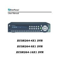
EAN Plus Series<br />
IP Box Camera<br />
Copyright © EverFocus Electronics Corp,<br />
Release Date: October, 2012<br />
User’s <strong>Manual</strong><br />
* Lens not included.
Copyright © 2012 EverFocus Electronics Corp.<br />
All rights reserved. No part of the contents of this manual may be reproduced or transmitted in any form or by<br />
any means without written permission of the EverFocus Electronics Corporation.<br />
EverFocus<br />
12F, No.79, Sec. 1, Shin-Tai Wu Road,<br />
Hsi-Chih, Taipei, Taiwan<br />
TEL: +886 2 2698 2334<br />
FAX: +886 2 2698 2380<br />
www.everfocus.com.tw<br />
October, 2012
Regulatory Notices<br />
About this document<br />
All the safety and operating instructions should be read and followed before the unit is operated. This<br />
manual should be retained for future reference. The information in this manual was current when<br />
published. The manufacturer reserves the right to revise and improve its products. All specifications are<br />
therefore subject to change without notice.<br />
FCC Notice "Declaration of Conformity Information"<br />
This equipment has been tested and found to comply with the limits for a Class<br />
A digital device, pursuant to part 15 of the FCC Rules. These limits are designed to provide reasonable<br />
protection against harmful interference in a residential installation. This equipment generates, uses and<br />
can radiate radio frequency energy and, if not installed and used in accordance with the instructions,<br />
may cause harmful interference to radio communications. However, there is no guarantee that<br />
interference will not occur in a particular installation. If this equipment does cause harmful interference<br />
to radio or television reception, which can be determined by turning the equipment off and on, the user<br />
is encouraged to try to correct the interference by one or more of the following measures:<br />
- Reorient or relocate the receiving antenna.<br />
- Increase the separation between the equipment and receiver.<br />
- Connect the equipment into an outlet on a circuit different from that to which the receiver is<br />
connected.<br />
- Consult the dealer or an experienced radio/TV technician for help.<br />
Warning: Changes or modifications made to this equipment, not expressly approved by EverFocus or<br />
parties authorized by EverFocus could void the user's authority to operate the equipment.<br />
This device complies with part 15 of the FCC Rules. Operation is subject to the following two conditions:<br />
(1) This device may not cause harmful interference, and<br />
(2) This device must accept any interference received, including interference that may cause undesired<br />
operation.<br />
EverFocus Electronics Corp.<br />
12F, No. 79, Sec. 1, Shin-Tai Wu Rd., Hsi-Chi,<br />
Taipei Hsien, Taiwan, R.O.C.<br />
EAN Plus-series cameras comply with CE and FCC.
Safety Notice<br />
These limits are designed to provide reasonable protection. This equipment generates, uses and can<br />
radiated radio frequency energy and, if not installed and used in accordance with the instructions, may<br />
cause harmful interference to radio communications. However, there is no guarantee that interference<br />
will not occur in a particular installation. If this equipment does cause harmful interference to radio or<br />
television reception, which can be determined by turning the equipment off and on, the user is<br />
encouraged to try to correct the interference by one or more of the following measures:<br />
- Reorient or relocate the receiving antenna.<br />
- Increase the distance between the equipment and the receiver.<br />
- Connect the equipment to an outlet on a circuit different from that to which the receiver is connected.<br />
- Consult the dealer or an experienced radio/TV technician for help.<br />
Any changes or modifications not expressly approved by the party responsible for compliance could void<br />
the user's authority to operate the equipment.<br />
To reduce risk of fire or electric shock, do not expose this appliance to rain or moisture.<br />
Do not attempt to disassemble the appliance. To prevent electric shock, do not remove screws or<br />
covers. There are no user-serviceable parts inside. Contact qualified service personnel for maintenance.<br />
Handle the appliance with care. Do not strike or shake, as this may damage the appliance.<br />
Do not use strong or abrasive detergents when cleaning the appliance body. Use a dry cloth to<br />
clean the appliance when it is dirty. When the dirt is hard to remove, use a mild detergent and wipe<br />
gently.<br />
Do not operate the appliance beyond its specified temperature, humidity or power source ratings.<br />
Do not use the appliance in an extreme environment where high temperature or high humidity exists.<br />
Use the appliance at a temperature between 0°C and 50°C / 32°F and 122°F and a humidity level<br />
between 0% and 80% non-condensing. The input power source for this appliance is 12VDC & PoE.<br />
Use only the recommended power supplies. Power supplies must comply with the requirement of<br />
the latest version of IEC60950-1. Substitutions may damage the unit or cause a fire or shock hazard.<br />
Electrostatic-sensitive device. Use proper CMOS/MOSFET handing precautions to avoid<br />
electrostatic discharge.<br />
Installation should be performed by qualified service personnel only in accordance with the<br />
National Electrical Code or applicable local codes.<br />
ii
Terms and Trademark<br />
Ethernet, Internet Explorer, Linux, Microsoft, Windows, WWW are registered trademarks of the<br />
respective holders. Other product names appearing in this User's Guide may be trademarks or registered<br />
trademarks of their respective holders. Java and all Java-related logos and trademarks are trademarks<br />
or registered trademarks of Sun Microsystems, Inc. in the United States and other countries.<br />
Support<br />
If the unit ever needs to be repaired or serviced, the customer should contact the nearest EverFocus<br />
Electronics Corp. Service Center for return authorization and shipping instructions.<br />
iii
CONTENTS<br />
1. Introduction ....................................................................................................................................... 1<br />
2. Overview ............................................................................................................................................ 2<br />
3. Features ............................................................................................................................................. 3<br />
4. Installation ......................................................................................................................................... 4<br />
4.1 Packing List ....................................................................................................................................... 4<br />
4.2 I/O Terminal Block ........................................................................................................................... 5<br />
4.3 Lens Installation and Adjustment .................................................................................................... 5<br />
4.4 Top / Bottom-Mount ....................................................................................................................... 6<br />
4.5 Basic Connection .............................................................................................................................. 7<br />
5. Accessing the User Interface ............................................................................................................... 8<br />
5.1 Assigning an IP Address ................................................................................................................... 8<br />
5.2 Settings for Microsoft Internet Explorer ........................................................................................ 10<br />
5.3 Connecting the Camera to the Network ........................................................................................ 12<br />
5.4 Live View Window .......................................................................................................................... 14<br />
6. Playback ........................................................................................................................................... 17<br />
6.1 Remote Playback Using Playback Page .......................................................................................... 17<br />
6.2 Setting up the Playback Function .................................................................................................. 19<br />
6.2.1 Preparing the Micro SD Card ............................................................................................. 19<br />
6.2.2 Testing the Playback Function ........................................................................................... 19<br />
6.3 Playing Back Using ARV Viewer ..................................................................................................... 21<br />
7 Settings ............................................................................................................................................ 22<br />
7.1 System Info .................................................................................................................................... 22<br />
7.1.1 Information ........................................................................................................................ 22<br />
7.1.2 Log ...................................................................................................................................... 23<br />
7.2 User Config ..................................................................................................................................... 24<br />
7.2.1 Live View Config ................................................................................................................. 24<br />
7.2.2 Recording / Snapshot ......................................................................................................... 25<br />
7.2.3 Language ............................................................................................................................ 26<br />
7.3 Network ......................................................................................................................................... 27<br />
iv
7.3.1 Network ............................................................................................................................. 27<br />
7.3.2 DDNS .................................................................................................................................. 29<br />
7.3.3 SMTP / FTP ......................................................................................................................... 31<br />
7.3.4 HTTPS ................................................................................................................................. 33<br />
7.3.5 SNMP .................................................................................................................................. 36<br />
7.3.6 Network Alarm ................................................................................................................... 36<br />
7.4 Video .............................................................................................................................................. 37<br />
7.4.1 Multi Streaming ................................................................................................................. 37<br />
7.4.2 Camera ............................................................................................................................... 39<br />
7.4.3 Advanced ........................................................................................................................... 41<br />
7.4.4 ROI (Region of Interest) ..................................................................................................... 48<br />
7.4.5 Privacy Mask ...................................................................................................................... 49<br />
7.5 Audio .............................................................................................................................................. 51<br />
7.6 User ................................................................................................................................................ 52<br />
7.6.1 User Information ................................................................................................................ 52<br />
7.6.2 IP Address Filter ................................................................................................................. 54<br />
7.7 Event .............................................................................................................................................. 55<br />
7.7.1 Event Settings .................................................................................................................... 55<br />
7.7.2 Motion Detection ............................................................................................................... 58<br />
7.7.3 Tamper Detection .............................................................................................................. 59<br />
7.7.4 Alarm I/O ............................................................................................................................ 59<br />
7.7.5 Schedule ............................................................................................................................. 60<br />
7.8 System ............................................................................................................................................ 61<br />
7.8.1 Date/Time .......................................................................................................................... 61<br />
7.8.2 Daylight Saving ................................................................................................................... 62<br />
7.8.3 SD Card ............................................................................................................................... 62<br />
7.8.4 Maintenance ...................................................................................................................... 63<br />
8. Upgrading Firmware Using IP Utility ........................................................................... 65<br />
9. Specifications ............................................................................................................. 67<br />
v
1. Introduction<br />
1<br />
EAN Plus Series<br />
The EAN Plus series is a box-type IP camera delivering image quality of up to 3-megapixel. The EAN Plus<br />
series features the Wide Dynamic Range (WDR) function, which can provide clear images even under<br />
back light circumstances where intensity of illumination can vary excessively. A built-in micro SD card slot<br />
and Power over Ethernet (IEEE802.3af) features are also provided. You can power the camera over the<br />
network or by connecting the camera to a 12V DC power supply. The camera also features H.264 /<br />
MJPEG multi-stream output for simultaneous live monitoring and high-resolution recording. Since the<br />
EAN Plus series conforms to ONVIF / PSIA for compatibility with other network video devices, it<br />
interoperates with a wide variety of hardware and software systems. The EAN Plus series is designed for<br />
simple installation and supports all types of indoor mounting applications.<br />
The EAN Plus Series Models<br />
Model Name Megapixel WDR<br />
EAN3120 Plus 1.3 MP Yes<br />
EAN3220 Plus 2 MP Yes<br />
EAN3300 Plus 3 MP No<br />
System Requirements<br />
Before installing, please check that your computer meets the following system requirements.<br />
Operating System Microsoft Windows XP / Vista (32-bit) / 7 (32-bit)<br />
CPU Intel Core2 Duo 2 GHz or higher<br />
1 GB or more<br />
RAM<br />
Additional HD space depends on required local storage of video files,<br />
100 Mbps network card.<br />
Screen Resolution 1024 x 768 pixels or higher, 32-bit pixel color resolution<br />
DirectX 9.0c<br />
Software<br />
Microsoft Internet Explorer 7 or higher<br />
Note: For using the Internet Explorer, some settings are required. Please refer to 5.2 Settings for<br />
Microsoft Internet Explorer.
2. Overview<br />
1<br />
2 3 4 5 6 7 8 9 10<br />
11<br />
2<br />
EAN Plus Series<br />
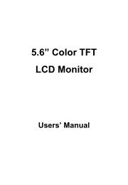
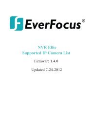
No. Item Name Descriptions<br />
1 Memory Card Slot Insert a micro SD / SDHC card to store recording data.<br />
2 Power LED Indicates the power is supplied.<br />
3 DC 12V Port Connects to power.<br />
4 Ethernet / PoE Connects to a 10/100 Ethernet or PoE.<br />
5 Reset Button Resets all configurations to factory default.<br />
6 I/O Terminal Block Connects I/O devices.<br />
7 Video Out<br />
Connects to a portable monitor for setting the focus and angle of<br />
the camera during initial installation.<br />
8 Audio In<br />
Connects to a microphone for audio input. Note that microphones<br />
with external power supplies are required.<br />
9 Audio Out Connects to a speaker for audio output.<br />
10 Light Sensor Detects lights.<br />
11 Auto Iris Lens Connector Plug the Iris control cable to the connector.
3. Features<br />
• 1/3” Panasonic CMOS sensor (for EAN3120 Plus / 3220 Plus)<br />
1/2.8” Sony CMOS sensor (for EAN3300 Plus)<br />
• Triple streams (stream 1 / 2 / 3 from H.264 or MJPEG)<br />
• Up to 30 fps at 1920 × 1080<br />
Supports 15 fps at 2048 × 1536 (only for EAN3300 Plus)<br />
• Auto Iris control<br />
• Built-in micro SD / SDHC card slot<br />
• Removable IR-cut filter for Day / Night function<br />
• One alarm input and output<br />
• Two-way audio<br />
• TV-out<br />
• Wide Dynamic Range (for EAN3120 Plus / 3220 Plus)<br />
• 2D / 3D Dynamic Noise Reduction (DNR)<br />
• Motion detection<br />
• Privacy mask<br />
• DC 12V / PoE<br />
3<br />
EAN Plus Series
4. Installation<br />
4.1 Packing List<br />
• EAN Plus Series Camera (lens not included) x 1<br />
• Software CD x 1<br />
• Quick Installation Guide x 1<br />
• Tool Packet x 1 (contains the following items)<br />
- C-mount lens adapter - ¼-20 UNC thread mounting bracket and 2 screws<br />
- Hexagon wrench - Power pigtail cable<br />
4<br />
EAN Plus Series<br />
Note: Contact the shipper if any items appear to have been damaged in the shipping process. If any<br />
items are missing, notify your EverFocus Electronics Corp. Sales Representative or Customer Service<br />
Branch. Please also keep the shipping carton for possible future use.
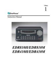
4.2 I/O Terminal Block<br />
5<br />
EAN Plus Series<br />
The I/O terminal block, located on the rear panel of the camera, can be used to develop application<br />
for alarm input and output.<br />
1 2 3 4<br />
Pin Assignment<br />
No. Function No. Function<br />
1 Alarm COM 3 Alarm Input<br />
2 Alarm Output 4 Digital GND<br />
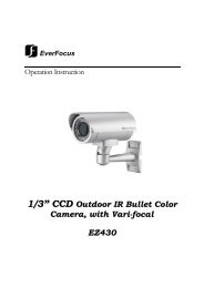
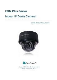
4.3 Lens Installation and Adjustment<br />
You can install either a CS-mount or a C-mount lens into the camera. It is recommended to use a lens<br />
with aperture ratio of F/1.4 or smaller. Please refer to the following reference steps.<br />
Focus Screw<br />
Zoom Screw<br />
C-Mount Lens Adapter<br />
DC Auto Iris Lens Connector<br />
CS-Mount Lens:<br />
1. Remove the cover cap from the camera body.<br />
2. Install the lens into the camera body.<br />
3. Adjust the lens using the Focus / Zoom Screws.<br />
If you are using a DC Auto Iris lens:<br />
1. Remove the cover cap from the camera body.<br />
2. Install the lens into the camera body.<br />
3. Connect the DC cable to the DC Auto Iris Lens Connector.
6<br />
EAN Plus Series<br />
4. When making final focus adjustment, place the ND filter in front of the lens to force the lens iris<br />
to open, and then adjust the lens using the Focus / Zoom Screws.<br />
Note: To use the ND filter, remove the protective sheets from both sides of an ND filter.<br />
5. Lock the Focus Screw and then remove the ND filter.<br />
C-Mount Lens:<br />
1. Remove the cover cap from the camera body.<br />
2. Install the lens into the camera body using the supplied C-mount lens adapter.<br />
3. Adjust the lens using the Focus / Zoom Screws.<br />
Note: Installing a C-mount lens without the C-mount lens adapter may damage the camera sensor.<br />
4.4 Top / Bottom-Mount<br />
You can use the supplied mounting bracket and screw it on the top of the camera body to suspend<br />
the camera, or on the bottom of the camera body to support the camera.<br />
Top Mount<br />
Bottom Mount
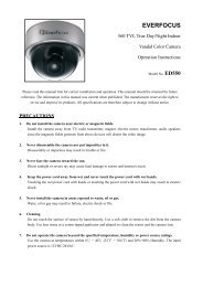
4.5 Basic Connection<br />
1<br />
2<br />
Micro SD Ethernet<br />
(PoE)<br />
Power DC 12V<br />
Reset<br />
COM<br />
Out<br />
In<br />
GND<br />
Alarm<br />
7<br />
Audio<br />
In Out<br />
Video Out<br />
1. Use a standard network cable to connect the camera to the network.<br />
2. Connect the camera to power using one of the following methods:<br />
• Plugging the supplied power pigtail cable to the DC 12V port.<br />
• Using the PoE function and the power will be provided over the network cable.<br />
5<br />
4<br />
EAN Plus Series<br />
3. Optionally connect the camera to a speaker or microphone. Note that microphones with<br />
external power supplies are required.<br />
4. Optionally connect the camera to a monitor using a BNC cable.<br />
5. Optionally connect the camera to the input / output devices.<br />
After powering the camera, the power LED will be lit in red and you can access the live view and<br />
adjust the image clarity.<br />
3<br />
3
5. Accessing the User Interface<br />
This section explains how to access the Web interface of the camera for configuration.<br />
5.1 Assigning an IP Address<br />
8<br />
EAN Plus Series<br />
You have to assign an IP address for your camera to be accessible. To assign an IP address to the<br />
camera, use the IP Utility (IPU) software included in the software CD. Please connect the IP camera in<br />
the same LAN of your computer.<br />
1. Install and then start the IPU program . The following dialog box appears.<br />
2. Click Find Devices to search the cameras connected in the LAN. The default network values of the<br />
cameras will be displayed. By default, the network protocol of the camera is DHCP.<br />
3. To configure the network settings, select a camera and then click Login/Multi Login to log in.
4. Type the user ID and password. Click OK.<br />
Note:<br />
1. The default user ID is user1 and the default password is 11111111.<br />
9<br />
EAN Plus Series<br />
2. If you select more than one camera that has the same user ID / password, you will be able<br />
to log in several cameras at once.<br />
5. To change the IP address, double-click the IP Address of the camera. Type a new IP address and<br />
then click Set IP Address to save the settings.<br />
You can also change the other settings by double-clicking the values. After configuring the values,<br />
click Save Configuration.<br />
Note: Most networks uses DHCP to assign IP address, if you are unsure of your network<br />
settings, please consult your network administrators for configuration details.<br />
6. To access the camera, highlight the camera and click Connect to Selected IP. The Internet<br />
Explorer window pops up.<br />
7. Type the user ID and password to log in. The Live View window of the camera appears.<br />
Note: You might be required to download ActiveX, which is required to view the camera feed.<br />
If asked, click "Yes". For more details on setting up the Microsoft Internet Explorer, please refer<br />
to 5.2 Settings for Microsoft Internet Explorer.
5.2 Settings for Microsoft Internet Explorer<br />
10<br />
EAN Plus Series<br />
To enable Remove Live View, Firmware Upgrade and ActiveX Prompt on Internet Explorer, some<br />
settings have to be complete. Please follow the steps below:<br />
1. On the computer, click Start > Control Panel > System and Security > Action Center (click Change<br />
User Account Control Settings), the User Account Control Settings window appears. Adjust the<br />
slide bar to Never Notify and then click OK. Restart your computer if requested.<br />
2. Open the Internet Explore, click Tools > Internet Options > Security Tab > Custom Level, the<br />
Security Settings windows appears.
11<br />
EAN Plus Series<br />
3. In the Download unsigned ActiveX controls field, select Prompt. In the Include local directory<br />
path when uploading files to a server field, select Enable. Click OK.<br />
4. In the Internet Options window, click the Advanced tab and then disable Enable memory<br />
protection to help mitigate online attacks. Click OK.
5.3 Connecting the Camera to the Network<br />
12<br />
EAN Plus Series<br />
There are three methods to connect the IP camera to the network: Router or LAN Connection, Direct<br />
High-Speed Connection and One-to-One Connection.<br />
Router or LAN connection<br />
This is the most common connection in which the IP camera is connected to a router and allows<br />
multiple users on and off site to see the IP camera on a LAN/WAN (Internet). The camera must be<br />
assigned an IP address that is compatible with its LAN. By setting up port forwarding on the router,<br />
you can remotely access the cameras from outside of the LAN via the Internet. To remotely access the<br />
Web interface of the IP camera, please refer to 7.3.2 DDNS. To set up port forwarding, please consult<br />
the manual of the router.<br />
Right: Pinout of a straight-through cable.<br />
Straight-through LAN patch cable
Direct High-Speed Connection<br />
13<br />
EAN Plus Series<br />
In a Direct High-Speed Connection, the camera connects directly to a modem without the need for a<br />
router. You need to set the static or dynamic WAN IP address assigned by your ISP (Internet Service<br />
Provider) in the camera’s configuration web pages. To access the camera, just type “http://xxx”,<br />
where xxx is the IP address given by your ISP. If you have a dynamic IP address, this connection may<br />
require that you use DDNS for a reliable connection. Please refer to 7.3.2 DDNS.<br />
One-to-One Connection (Directly from PC to IP Camera)<br />
You can connect directly without using a switch, router or modem. However, only the PC connected<br />
to the camera will be able to view the IP camera. You will also have to manually assign a compatible IP<br />
address to both the computer and the IP camera. Unless the PC has another network connection, the<br />
IP camera will be the only network device visible to the PC. See the diagram below:<br />
Pinout of straight patch cable<br />
Right: Pinout of a crossed-over cable.
5.4 Live View Window<br />
14<br />
EAN Plus Series<br />
1. Press the button to display the "Live View" window. Double-click on the<br />
image to show a full-screen display, double-click again or press ESC to return to the normal display.<br />
If you experience video feed lag time (if connected via Internet), you can reduce the resolution or<br />
limit the number of streams. See 7.4.1 Multi Streaming.<br />
2. Press the button to play the recorded data directly from the on-camera Micro<br />
SD / SDHC card (for this function to become active, you have to insert a Micro SD / SDHC card in the<br />
Micro SD / SDHC card slot on the rear panel of the camera. See 7.8.3 SD Card.<br />
3. Press the button to enter the Settings page. On the Settings page, there are<br />
8 submenu sections: [System Info], [User Config], [Network], [Video], [Audio], [User], [Event], and<br />
[System]. Click on the section buttons to open their configuration fields. See the Settings section<br />
below for more information.
4. Press the button to exit the system and close this browser page.<br />
5. Video Stream<br />
15<br />
EAN Plus Series<br />
Select the Video Stream (Stream 1, Stream 2 or Stream 3) that will be displayed in the video box on<br />
the right. Stream 2 and Stream 3 are only selectable if you have enabled the stream. The default<br />
setting is Stream 1 only. See 7.4.1 Multi Streaming.<br />
6. View Size<br />
Use this to select the appropriate view size and shape of the video box on the right. A smaller size<br />
might increase transmission speed and video quality.<br />
7. Digital Zoom<br />
Click the Zoom In / Zoom Out buttons or roll the mouse wheel to zoom in / out the camera live view<br />
up to 10x. Clicking on a magnified image will re-center the image around that point.<br />
8. Record<br />
The Record button is used to record the current video stream. Click the Record button to start /<br />
stop recording. This icon is only for one-minute video recording. To record long-period recordings,<br />
please set a recording schedule (See 7.7.5 Schedule). The location on your computer, where the<br />
image files will be saved to, and file size can be specified in the submenu (see 7.2 User Config).<br />
9. Snapshot<br />
Click the Snapshot button to save a snapshot of the video image currently being displayed. The<br />
location on your computer where the snapshot data will be saved can be specified in “Settings ><br />
User Config > Recording/Snapshot” (see 7.2 User Config).<br />
10. Play Audio / Transmit Audio<br />
Click the “Play Audio” (speaker) and “Transmit Audio” (microphone) buttons to switch the sound<br />
on/off for the speaker and microphone, respectively (if such external devices have been connected<br />
to the camera directly or via the network).
16<br />
EAN Plus Series<br />
11. One Push<br />
This function is only available for EAN3120 Plus / 3220 Plus. The One Push button can be displayed<br />
on the live view window by enabling the Show One Push Buttons function on the User Config < Live<br />
View Config Setting page (see 7.2.1 Live View Config). To enable the button (turned from faded to<br />
clear), on the Video < Advanced Setting page, select One Push from the White Balance Settings<br />
Mode drop-down list, and click the Apply button. Once this is done, pressing the One Push button<br />
on the Live View Window will instruct the camera to adjust the white balance settings, and these<br />
settings will be active until the button is pushed again. This is like a “semi-automatic” way to adjust<br />
white balance to suit the user, if the Auto or <strong>Manual</strong> mode does not give the result the user wants.<br />
12. <strong>Manual</strong> Control<br />
– Trigger Event<br />
Press the “Trigger Event” button to trigger an event directly from the Live page. If you have<br />
configured an event (in the Event submenu) that will trigger a reaction (like a recording) when a<br />
<strong>Manual</strong> Trigger event occurs, clicking this button will trigger that reaction. You can select what that<br />
reaction will be. You can, for instance, set the camera to record the audio/video feed to the Micro<br />
SD card on board the camera. You can then click on the Playback button to open the Playback page<br />
and search for and play all such recordings that had been stored on the card. Such event actions<br />
will be effective once they have been configured in the “Event” menu (see 7.7 Event).<br />
– Reset Alarm<br />
Press the “Reset Alarm” button to reset the alarm output remotely.<br />
13. Status Display (info lines that can be placed above video box or at bottom of page)<br />
This shows the name of the camera that is currently active or being configured, current date/time<br />
and current frame rate. You can activate these info displays in the Settings > User Config page (see<br />
7.2 User Config).<br />
14. Event Signal Icons (above video screen)<br />
When an alarm or motion event is triggered, a signal icon will appear at the top right of the Live<br />
View window to alert the user.<br />
Alarm event icon : When an alarm is triggered, this icon appears.<br />
Motion detection icons : The colors of these motion event icons correspond to the<br />
colors of the motion trigger areas you have configured in the Motion Detection submenu (see 7.7.2<br />
Motion Detection).<br />
Recording icon : When the camera is recording to a PC-based folder, this icon appears.
6. Playback<br />
17<br />
EAN Plus Series<br />
You can remotely play back the recordings stored in the on-camera micro SD card on the Web interface,<br />
or play back the recordings stored in the computer using the ARV Viewer included in the software CD.<br />
Playback is designed as a quick way to check recent recordings that were triggered by Events that were<br />
configured to “Record to SD Card” in the Settings > Event > Event Settings page (see 7.7.1 Event<br />
Settings).<br />
Note: Note that the Playback page is only accessible once the on-camera SD card is inserted and<br />
active.<br />
6.1 Remote Playback Using Playback Page<br />
On the Live View Window, click the Playback button to open the Playback page.
18<br />
EAN Plus Series<br />
Search by File: Click the Search button to search for all recording files on the on-camera SD card.<br />
Search results will be displayed in the Filename area.<br />
Search by Time: Click the calendar icon and select the date and time from which you want to search<br />
until the present moment. Click search to get your search results, which will be displayed in the<br />
Filename area.<br />
Search by event: Click the type of Event recordings you want to search for (Alarm, Motion, <strong>Manual</strong><br />
Trigger) and then click the calendar icons to select the Start Time date/time and the End Time<br />
date/time of your search. Click Search to get your search results, which will be displayed in the<br />
Filename area.<br />
Multiple Files: Check this box if you want the video player to play all the files in the selected folder.<br />
The files will be displayed in the Filename area.<br />
Loop Again: Check this box if you want the video player to play the selected file over and over again.<br />
Play: Once you have opened the file’s folder and have clicked on the file to highlight it, its details will<br />
be displayed in the File Information area. You can now click Play to play that specific file.<br />
Pause: Click this button to pause the playback.<br />
Stop: Click this button to stop the playback.<br />
【Recording List】<br />
Filename: This area will display a list of search results (recording files and folders). Folders (named<br />
with the recorded date) will be displayed first. Click on the folder and click on each subfolder until the<br />
recording files (.arv) in that folder is listed.<br />
File Information: Click a file on the Filename list, the selected file information will be listed.<br />
Copy: Click this button to copy the selected file to the computer-based folder of your choice. A<br />
browsing box will open so that you can search for the folder of your choice. You can use the ARV<br />
Viewer to play back the recordings recorded in your computer. For details on ARV Viewer, see 6.3<br />
Playing Back Using ARV Viewer.<br />
Lock: Click this button to lock the selected file. This will protect that file from being overwritten during<br />
any overwrite procedure. The file will thus be saved on the micro SD card indefinitely. However, the<br />
file will still be deleted if the micro SD card is ever formatted.<br />
Remove: Click this button to delete the selected file.
6.2 Setting up the Playback Function<br />
19<br />
EAN Plus Series<br />
Note that the Playback function will not be active until the user has inserted a micro SD card in the<br />
camera’s micro SD card slot. The card may also have to be formatted in the Settings submenu.<br />
Micro SD Card Slot<br />
6.2.1 Preparing the Micro SD Card<br />
Once you insert a functional micro SD card into the slot, the Playback button on the Live page should<br />
become active within seconds (see section 6.2.2 below – the grey letters should turn white). IF NOT,<br />
do the following:<br />
1. From the Live page, click Settings > System > SD Card. If no card has been inserted yet, the<br />
Remove button should be faded, indicating that no card is being detected. (If a card is<br />
inserted, and the Remove button is still faded, pull the card out and re-insert it.)<br />
2. Slide the card into the slot until it clicks into position.<br />
3. The Remove button should become active within a few seconds, indicating the card is active.<br />
4. If the Remove button stays faded, click the Format button to format the card. NOTE: All data<br />
on the disk will be deleted if the Format button is clicked.<br />
6.2.2 Testing the Playback Function<br />
1. Once the SD card is detected by the system, the button (inactive)<br />
will turn to (active).<br />
2. To test the Playback function (this is not required), set up a “<strong>Manual</strong> Trigger” Recording<br />
Event by clicking Settings > Event > Event Settings.<br />
3. Click the “Add” button on the middle right side of the page to open an “Add Event” box.<br />
4. Give the event a name, like “Test 1”.
5. In the “Event Triggered by” field, click on <strong>Manual</strong> Trigger.<br />
20<br />
EAN Plus Series<br />
6. Below this, check “Enable This Event”, “Enable Post-trigger Buffer”, and “Record to SD Card”.<br />
7. To save your settings, click OK, or close the box by clicking on the red x icon at top right of the<br />
box (in which case you will be asked if you want to save the data, to which you should reply OK).<br />
The box will close and the new event will be listed in the list area of the Event Settings page.<br />
8. Look at the “Post-trigger Buffer” at the bottom to make sure the buffer time is set to 10 seconds.<br />
9. Click “Apply” to make sure all settings are saved.<br />
10. Click the Live button to go back to the Live page.<br />
11. Get ready to click the Trigger Event button at the bottom of the page. Before you do, see if you<br />
can find something in the view screen that will give you a visual time marker. For instance, if you<br />
can get your hand in front of the camera’s lens, get ready to count down on your fingers.<br />
12. Click the Trigger Event button and slowly count down on your fingers in front of the lens (if you<br />
are able to do so – if not, try to find visual cues on the view screen that will help you to mark the<br />
moment you pushed the trigger). The recording period will be as long as the buffer time you<br />
selected – the default period is 10 seconds.<br />
13. Click the Playback button to open the Playback page.<br />
14. There are different ways to search for recording files on the camera’s Micro SD card (i.e. the<br />
Playback memory). For a recent recording like your test event, simply click the “Search” button<br />
under the “Search by File” header.<br />
15. If the SD card is active and formatted correctly, the recording folder’s name (the recording day’s<br />
date) will appear in the Filename box at the bottom. Click on this folder to open it. If there are<br />
sub-folders, click on the bottom one (the most recent would be at the bottom) until you can click<br />
on a file that cannot open to another sub-level and shows data in the File Information box to the<br />
right. This would be the file of the most recent recording event.<br />
16. To play this file, click the Play button below the video box. The test footage you have recorded<br />
should start playing. Play time should be 10 seconds if you left the Post-trigger Buffer as 10<br />
seconds.
6.3 Playing Back Using ARV Viewer<br />
21<br />
EAN Plus Series<br />
You can play back the recordings stored in the computer using the ARV Viewer included in the<br />
software CD. To store the recordings in the computer, please refer to Recording List > Copy in 6.1<br />
Remote Playback using Playback Page.<br />
4 5 6 7 8 9 10<br />
No. Item Name Descriptions<br />
1 Snapshot Click to take and save a snapshot.<br />
1<br />
2 Load File Click to load the recordings for playing back.<br />
3 Convert ARV to AVI Convert the recording from ARV format to AVI format.<br />
4 Playback Time Display the playback time.<br />
5 Total Time of Recording Display the total time of the recording.<br />
6 Stop Click to stop playing the recording.<br />
7 Step Reverse Click to display the previous frame.<br />
8 Play Click to play back the recording.<br />
9 Pause Click to pause the recording.<br />
10 Step Forward Click to display the next frame.<br />
2<br />
3
7 Settings<br />
22<br />
EAN Plus Series<br />
Click the Settings button on the Live View Window to enter the settings submenu. There are nine buttons<br />
on the left-side of the submenu: Live, System Info, User Config, Network, Video, Audio, User, Event and<br />
System. Click the Live button can go back to the Live View Window.<br />
7.1 System Info<br />
The System Information and System Log can be checked on this page. Click the top tab of the one you<br />
want to see.<br />
7.1.1 Information<br />
Click the Information tab, the following dialog box appears. These values cannot be changed on this<br />
page, and are for reference only.
7.1.2 Log<br />
23<br />
EAN Plus Series<br />
Click the Log tab, the following dialog box appears. The sequence number, date, time and event<br />
messages of the log event will be displayed in the System Log field. The log will display the last 256<br />
log events. Click the Export button to export the system log event list into a “.txt” file and select the<br />
location where the exported log file will be saved to.
7.2 User Config<br />
24<br />
EAN Plus Series<br />
Each user can set a different configuration for his/her Live page here. These settings will be applied to<br />
the logged-in user’s Live page every time he/she logs in.<br />
7.2.1 Live View Config<br />
【Video/Audio Connection Protocol Setting】You can transmit the data stream from the IP cameras<br />
using the RTSP (Real Time Streaming Protocol) on the network. The RTSP is a protocol that allows<br />
you to access video streams by using the compatible media players. Click Apply to apply the<br />
changes or Reset to reset without saving the changes.<br />
RTP over UDP: The RTSP protocol uses UDP for camera data stream transmission.<br />
RTP over TCP: The RTSP protocol uses TCP for camera data stream transmission.<br />
RTP over HTTP: The RTSP protocol uses HTTP for camera data stream transmission.<br />
Nevio CGI: This is EverFocus’ protocol designed for EverFocus’ IP devices. Select this<br />
protocol for camera data stream transmission.<br />
【Text Settings】Check the box of each option (Machine name, Date/Time, Frame Rate) to display<br />
this info on the Live View Page.<br />
Foreground Color: Slide the Red, Green and Blue bars to create your preferred text color for the<br />
info text line.<br />
Position: Select the position where the text will be displayed. Choose from Upper Left / Lower<br />
Right / Lower Left.<br />
Click Apply to apply the changes or Reset to reset without saving the changes.
25<br />
EAN Plus Series<br />
【Date/Time Format Used in Text】Click the dropdown menu to select date/time format from the<br />
listed options. Click on the desired hour format. Click Apply to apply the setting changes or Reset to<br />
reset without saving the change.<br />
【Live View Layout Settings】 Check the “Show One Push Buttons” boxes if you want to show these<br />
buttons on the Live View Page. Uncheck these boxes to hide these buttons. This function is only<br />
available for EAN3120 Plus / 3220 Plus.<br />
7.2.2 Recording / Snapshot<br />
This configures where your Record Button and Snapshot Button ( ) files will be saved if<br />
you click one of these buttons. Selectable folders will be on the computer only, not on the<br />
on-camera SD card.<br />
【Recording / Snapshot Export Settings】<br />
Enable Event Recording to PC: Checking this box will let the system save Record/Snapshot Button<br />
recordings to the folder configured below on the user’s PC.<br />
Export Folder: Select the Export folder for the action above by clicking on the browse (…) button,<br />
and then select the desired folder.<br />
File size: The user can limit the size of each recorded file here (in minutes). When a single<br />
recording file exceeds the time you set, the system will create a new file to save that data to.<br />
Overwrite: Select “ON” for overwriting recording/snapshot file when the disk storage capacity is<br />
full. The user can set the storage capacity limitation in the in-sentence field in the gray box below<br />
the Overwrite setting: “If the remaining hard disk capacity is less than ____ MB (50~2000), system<br />
will stop recording or start overwriting. “<br />
Click Apply to apply the setting changes or Reset to reset without saving the changes.
7.2.3 Language<br />
26<br />
EAN Plus Series<br />
Select the language to be displayed on the Web interface of the IP camera. The default language is<br />
English.<br />
To add a new language not listed in the current Language list, click the Browse button to locate<br />
the new language file (.evb) on your computer and then click the Upload button. Updated<br />
language files might be available on the manufacturer’s website. Contact your vendor if required.<br />
Click Apply to apply any changes or Reset to reset without saving the changes.<br />
Note: Uploading a new language file will cause the system to reboot automatically. Please create<br />
a new network connection to the IP camera when the reboot is complete.
7.3 Network<br />
27<br />
EAN Plus Series<br />
This page covers network-related settings, including Network, DDNS, SMTP/FTP, HTTPS, SNMP, and<br />
Network Alarm.<br />
7.3.1 Network<br />
The following information is required to configure the network settings. Contact your network<br />
administrator or your internet service provider to get the info.<br />
【IP Settings】<br />
IP Type: Refer to the network administrator for these settings of the server. Default: DHCP<br />
DHCP: This setting lets the system use an automatically assigned (dynamic) IP address. This<br />
address can change under certain circumstances. For instance, when the camera’s network<br />
switch/hub has to be rebooted. Do not assign to the DHCP server the same IP addresses used<br />
for the other network cameras and PCs with unique IP addresses.<br />
Static IP: The user can manually set the Static IP address. This type of address is stable and<br />
cannot change, but the user has to make sure there are no address conflicts with other<br />
network-connected devices.<br />
PPPoE: This is a DSL-connection application. The ISP will ask the user to input a username and<br />
password. Contact your ISP for these details.
28<br />
EAN Plus Series<br />
Note: If PPPoE is selected as the IP type, the supplied IP Utility program will not be able to<br />
detect the device.<br />
IP address: When DHCP is not used, the user needs to manually enter the IP address of the<br />
camera. Do not enter an IP address that is already used for your computer or other network<br />
cameras.<br />
Subnet Mask: This field is used to set the netmask for your network, so that the IP camera will be<br />
recognized within the network. Example: 255.255.255.0. When DHCP is selected, the DHCP server<br />
will assign this value automatically.<br />
Gateway: This field is used to set the gateway for your network so that the IP camera will be<br />
recognized within the network. When DHCP is selected, the DHCP server will assign this value<br />
automatically.<br />
Primary DNS: Enter the IP address of the DNS server if this is provided by an ISP.<br />
Secondary DNS: If your ISP provided you with a secondary DNS address, please enter it here.<br />
Username: Enter the account’s username (used only for PPPoE).<br />
Password: Used only for PPPoE.<br />
IPv6: Enter the IPv6 details in this area, if this applies to your system.<br />
Click Apply to apply the setting changes or Reset to reset without saving the change.<br />
【Port Settings】Enter the HTTP, HTTPS and RTSP port numbers and click Apply to save.<br />
【Multicast Settings】Enable if required, fill in the setting options and click Apply to save.
7.3.2 DDNS<br />
29<br />
EAN Plus Series<br />
DDNS (Dynamic Domain Name System) is a service used to map a domain name to the dynamic IP<br />
address of a network device. You can set up the DDNS service for remote access to the IP camera.<br />
DDNS assigns a domain name (URL) to the IP camera, so that the user does not need to go through<br />
the trouble of checking if the IP address assigned by DHCP Server has changed. Once the IP is<br />
changed, the IP camera will automatically update the information to the DDNS to ensure it is always<br />
available for remote access.<br />
Before enabling the following DDNS function, user should have applied for a host name from the<br />
DDS service provider’s website. We support these four DDNS server providers:<br />
www.everfocusddns.com, www.sitelutions.com, www.dyndns.com, and www.no-ip.com<br />
Note: We highly recommend that you use xxxx.everfocusddns.com for the simplicity of setting up<br />
your IP cameras.<br />
【DDNS Settings】<br />
Enable: Check this box to enable the DDNS function.<br />
Service ISP: You can either apply for a host name from EverFocus or other DDNS server providers.<br />
If you choose the EverFocus DDNS server, you can obtain a free host name from EverFocus by<br />
following the steps below:<br />
• From EverFocus: To obtain a free host name from EverFocus, type a desired host name in the<br />
textbox, click the Register / Update button, and then click the Apply button.<br />
• From other DDNS server providers: To obtain a domain name from one of the three DDNS<br />
server providers, you have to register your name with the provider first, and then select the<br />
provider and fill in the required information. Please refer to the specific DDNS company’s<br />
website for further information.<br />
Record ID: Type the record ID if provided by the DDNS server provider.
30<br />
EAN Plus Series<br />
FQDN: Type the fully qualified domain name applied from the DDNS server provider. For<br />
example, xxxx.dyndns.com<br />
Username / Password: Type the login account of your DDNS server provider.<br />
Click Apply to apply the setting changes or Reset to reset without saving the changes.<br />
Note:<br />
1. In order to support the full functionality of the camera, you must open the port numbers (80,<br />
554, 443) on the router for remote access to the IP camera. This function is available on most<br />
routers in the market and is often known as “Port Forwarding”. To set up Port Forwarding,<br />
please consult the manual of the router.<br />
2. In certain router models, it is possible that you will not be able to access the camera using<br />
DDNS while inside the router’s network. Please try using a PC located outside of your router’s<br />
network.<br />
Default Ports on All EverFocus IP Cameras:<br />
HTTP: 80<br />
RTSP: 554<br />
HTTPS: 443
7.3.3 SMTP / FTP<br />
31<br />
EAN Plus Series<br />
【Set SMTP Server (email)】This area is for configuring the mail server that is used to send e-mail<br />
notifications from the camera to predefined addresses via SMTP. Note that to enable e-mail<br />
notification function, you have to check the Send Mail Notification item on the Event dialog box<br />
(see 7.7.1 Event Settings).<br />
SMTP Server: Enter the IP address or the host name of the SMTP server used to send e-mails.<br />
SMTP Port: Enter the port number for SMTP. The default is 25.<br />
Authentication: Check this box if the SMTP server requires authentication (user/password).<br />
User name: Input the user’s login ID if the SMTP server requires authentication.<br />
Password: Input the user’s login password if the SMTP server requires authentication.
32<br />
EAN Plus Series<br />
Receiver Address: Input the e-mail addresses for receiving an e-mail message when an EVENT is<br />
enabled and triggered. Please use “;” to separate multiple addresses.<br />
Sender Address: Input the sender’s e-mail address, so that the receiver can recognize the sender<br />
when an Event message is received.<br />
Attach Image: Check this box if you want to attach an image when an alarm is triggered or an IP<br />
camera detects events.<br />
Send Test Email: Click the Test button to send a testing email to the assigned address.<br />
Click Apply to apply the setting changes or Reset to reset without saving the changes.<br />
【Set FTP Server】The settings relating to the FTP server used to transmit the alarm images can be<br />
configured here. Note that to enable uploading images to the FTP server function, you have to<br />
check the Upload to FTP item on the Event dialog box (see 7.7.1 Event Settings).<br />
FTP Server: Enter the IP address or the host name of the FTP server.<br />
FTP Port: Enter the port number for the FTP server. Default is 21.<br />
Recording Path: Assign the recording path.<br />
User Name: Set FTP User’s name.<br />
Password: Set FTP password.<br />
PASV mode: Check to enable Passive mode. Passive mode is normally enabled. If a connection<br />
cannot be established, uncheck "PASV Mode”.<br />
Test FTP Server: Click the Test button to send a testing file to the assigned FTP server.<br />
Click Apply to apply the setting changes or Reset to reset without saving the changes.
7.3.4 HTTPS<br />
33<br />
EAN Plus Series<br />
Hypertext Transfer Protocol Secure (HTTPS) is a combination of the Hypertext Transfer Protocol<br />
and the SSL/TLS protocol and provides encrypted communication and secure identification of a<br />
network web server.<br />
Before using the HTTPS function for communication with the IP camera, a Certificate must be<br />
created first. There are two ways to create and install a certificate: Create Self-Signed Certificate<br />
and Create Certificate Request.<br />
Create Self-Signed Certificate<br />
Please note that even though self-signed certificates are free and offer some protection, true<br />
security is only implemented after the installation of a signed certificate issued by a certificate<br />
authority.<br />
1. Click the Create Self-Signed Certificate button, the following dialog appears.
34<br />
EAN Plus Series<br />
2. Type the required Certificate information and then click the Apply button. The subject line will<br />
be displayed in the Installed Certificate Information field.<br />
3. Click the Property button, a pop-up window appears to display the details of the certificate.<br />
4. To optionally create and install other certificates, remove the existing one by clicking the<br />
Remove button to erase the certificate.<br />
5. On the Web page, change the address from “http://” to https:// in the address bar and press<br />
Enter on the keyboard. Some Security Alert dialogs will pop up. Click OK or Yes to enable HTTPS.<br />
Create Certificate Request<br />
You can apply for an official certificate from an issuing Certificate Authority.<br />
1. Click the Create Certificate Request button, the following dialog appears.
35<br />
EAN Plus Series<br />
2. Type the required Certificate information and then click the Apply button. The subject line will<br />
be displayed in the Created Request field<br />
3. Click the Property button, a pop-up window appears to display the details of the certificate.<br />
4. To optionally create and install other certificates or request, remove the existing one by clicking<br />
the Remove button to erase the certificate or request.<br />
5. Copy the contents of the Certificate request (in PEM format) and paste it to the certificate<br />
request field on the Web page of the 3 rd -party certification authority such as Symantec VeriSign.<br />
Wait for the certificate authority to issue an SSL/TLS certificate and then download the issued<br />
certificate on your computer.<br />
6. In the Install Signed Certificate field, click the Browse button to search for the issued certificate,<br />
and then click the Upload button to import the certificate. Once the certificate has been<br />
uploaded, this field will show the subject line of the certificate.
7.3.5 SNMP<br />
36<br />
EAN Plus Series<br />
The default values for SNMP v1/v2/v2c and SNMP v3 are already filled in. Click either of the<br />
Enable buttons to enable either of the two. Make your changes as desired. Click on the Trap<br />
Address field to enter the digits, if required.<br />
7.3.6 Network Alarm<br />
This function works with EverFocus’s CMS software, e.g. the PowerCon or the Power Video Plus. For<br />
the setting details, please refer to the CMS network alarm protocol.
7.4 Video<br />
37<br />
EAN Plus Series<br />
The settings relating to video such as streaming, camera OSD can be configured on this page. The<br />
"Video" page has five tabs: Multi-streaming, Camera, Advanced, ROI and Privacy Mask.<br />
7.4.1 Multi Streaming<br />
【Stream Settings】 This IP camera can output three video streams simultaneously. For each of these<br />
streams, the user can set the compression format, resolution, bit rate, and frame rate individually.<br />
Stream 1 is always enabled for live view. To enable Stream 2 and/or Stream 3, check the “Enable”<br />
box the header of each stream.<br />
Note: If you connect to the camera via the Internet and experience a delay (lag time) in the video<br />
feed, try to reduce the number of streams and the quality and resolution of the streams – but<br />
keep the frame rate at its maximum.
Format: Select the encoding format – H.264 or MJPEG.<br />
Resolution: Select the most suitable resolution for your needs.<br />
Frame Rate: Select from 1 to 30 fps.<br />
38<br />
EAN Plus Series<br />
Bit Rate: If required, select whether you want the stream to stream a Constant Bit Rate or a<br />
Variable Bit Rate, and set the values of whichever option you choose.<br />
Click Apply to apply the setting changes or Reset to reset without saving the changes.<br />
【Video Recording Settings】Select the stream you want to configure and then select whether you<br />
want the recording files of that stream to be saved in AVI or ARV format. Click Apply to apply the<br />
setting changes or Reset to reset without saving the changes.<br />
【Time Stamp Settings】 You can select the Date/Time format, position, and add the setting to the<br />
streaming.<br />
Click Apply to apply the changes, or Reset to reset without saving the changes.
7.4.2 Camera<br />
39<br />
EAN Plus Series<br />
【Image Settings】Set the Brightness, Saturation, Contrast or Sharpness of the image. Click Apply to<br />
apply the changes, or Reset to reset without saving the changes.<br />
【Camera Settings】<br />
Mirror: Switch Mirror ON to rotate the image horizontally around a vertical axis.<br />
Flip: Switch Flip ON to rotate the image vertically around a horizontal axis.<br />
AE: There are two options:<br />
ALC: Selecting Automatic Light Control allows the camera circuitry to either take bright spots<br />
more into consideration (peak), bringing out detail in bright areas, or less into consideration<br />
(average) bringing out detail in shadows.<br />
AES: Selecting Auto Electronic Shutter disables the Shutter setting below this setting. In this<br />
mode, the camera measures the light level and decides whether it needs more or less light and<br />
then automatically adjusts the shutter speed accordingly.<br />
BLC: Back Light Compensation (BLC) is used to make the subject appear clearer when it is set<br />
against a bright background.<br />
OFF: Select to switch Back Light Compensation functions off.<br />
(ON)BLC: The BLC can increase the exposure of a dark area surrounded by a brighter area, HLC<br />
can decrease the exposure of bright areas surrounded by darker areas. This enables the<br />
camera to better display information that would otherwise have been “whited out”, like a<br />
license plate between two bright headlights on a dark road.<br />
(ON)HLC: The Highlight-Suppression BLC is used to reduce the brightness of light sources in a<br />
specific area. It is activated only in a low illumination environment to minimize the effects of<br />
glare from bright lights such as spotlights, street lights or headlights in the field of view.
40<br />
EAN Plus Series<br />
WDR: The Wide Dynamic Range (WDR) function provides clearer images when both of the very<br />
bright and dark areas simultaneously appear on the camera view. There are four value options:<br />
OFF, Low, Middle and High. Note that when WDR is ON, some parts of the image may appear<br />
solarized. This is normal for WDR, and is not a camera malfunction. This function is only available<br />
for EAN3120 Plus / 3220 Plus.<br />
D/N Mode<br />
Auto: Select to let the camera automatically switch to Night mode (black and white) when the<br />
light levels fall to a specified level, and back to Day mode (color) when the light levels rise to a<br />
specified level.<br />
Day: Select to keep the camera in Day mode (color), even in nighttime.<br />
Night: Select to keep the camera in Night mode (black and white), even in daytime.
7.4.3 Advanced<br />
41<br />
EAN Plus Series
【Camera Settings】<br />
42<br />
EAN Plus Series<br />
Lens (IRIS Control): Select DC or <strong>Manual</strong> for IRIS control. This function is only available for EAN3220<br />
Plus.<br />
Exposure Settings (AE): This setting is used to adapt to the amount or type of light used by the<br />
camera. Note the settings vary among models.<br />
Mode: This function is not available for EAN3220 Plus.<br />
Automatic Light Control (ALC): This option is only available for EAN3120 Plus / 3300 Plus. The<br />
ALC allows the camera circuitry to either take bright spots more into consideration (peak),<br />
bringing out detail in bright areas, or less into consideration (average) bringing out detail in<br />
shadows.<br />
Auto Electronic Shutter (AES): This option is only available for EAN3120 Plus / 3300 Plus. In<br />
this mode, the camera measures the light level and decides whether it needs more or less light<br />
and then automatically adjusts the shutter speed accordingly.<br />
<strong>Manual</strong>: This option is only available for EAN3300 Plus. Select this option to manually set up<br />
the Shutter (<strong>Manual</strong>) and AGC (<strong>Manual</strong>) values.<br />
Iris: Specify the size of the Iris opening here.<br />
Shutter: If enabled, this setting lets you set the shutter speed yourself.<br />
Shutter Limit: Use this setting to set the maximum shutter speed for the camera. This function is<br />
only available for EAN3120 Plus.<br />
AGC: Set the Auto Gain Control limit here. The lower the AGC level, the lower the video signal and<br />
the noise. However, the image will be darker under low-light condition with IR-off if you set up the<br />
Iris to the maximum level.<br />
Slow Shutter: This option can be switched on when AES Mode is selected in the Exposure Settings<br />
(AE) field. This function is only available for EAN3220 Plus / 3300 Plus.<br />
Flickerless: If the Mode field in the Exposure Settings (AE) area has been set to AES, then this option<br />
becomes available. Choose between OFF, 50HZ, 60HZ, 50HZ (High Luminance) or 60HZ (High<br />
Luminance). This function is only available for EAN3300 Plus.<br />
EV Setting: Set up the Exposure Value. Note the brightness of the screen changes when you change<br />
the EV value. This function is only available for EAN3300 Plus.<br />
AE Response: Set up Auto Exposure Response time. This function is only available for EAN3300 Plus.<br />
AE Weighting Area: Select an AE Weighting area. Each setup AE Weighting Area is configured with<br />
the appropriate brightness level on the center and the surrounding areas. This function is only<br />
available for EAN3300 Plus.<br />
Brightness: Set the image brightness here.<br />
AE Reference: Set the Auto Exposure value here. This function is only available for EAN3120 Plus.
Black Level: Set the Black level here. This function is only available for EAN3300 Plus.<br />
43<br />
EAN Plus Series<br />
WDR: The Wide Dynamic Range (WDR) function provides clearer images when both of the very<br />
bright and dark areas simultaneously appear on the camera view. There are four value options: OFF,<br />
Low, Middle and High. Note that when WDR is ON, some parts of the image may appear solarized.<br />
This is normal for WDR, and is not a camera malfunction. This function is only available for EAN3120<br />
Plus / 3220 Plus.<br />
Visibility Enhancement: (OFF/Low/Middle/High) Images in foggy or rain environments or in<br />
environments with a very strong luminous intensity have a dynamic range that is significantly lower<br />
than ordinary images. The user can use this Visibility Enhancement setting to “DEFOG” the image if<br />
such “FOGGING” is an issue. This function is only available for EAN3220 Plus.<br />
BLC Settings: Back Light Compensation (BLC) is used to make the subject appear clearer when it is<br />
set against a bright background.<br />
OFF: Select to switch Back Light Compensation functions off.<br />
Back Light: This option is only available for EAN3300 Plus. The Back Light function is useful<br />
when the background of the subject is very bright and the subject itself is dark. Select Back<br />
Light and adjust the slide bar to the left / right for setting up the back light value. The higher<br />
the value, the more the backlight compensation.<br />
Front Light: This option is only available for EAN3300 Plus. This function is useful when the<br />
bright highlights, such as flashlight or car headlights, appear on the camera view. Select Front<br />
Light and adjust the slide bar to the left / right for setting up the front light value. The higher<br />
the value, the more the highlight compensation.<br />
ON (BLC): This option is only available when you select AES Mode in the Exposure Settings (AE)<br />
field. The option is only available for EAN3120 Plus / 3220 Plus. The BLC function is useful<br />
when the background of the subject is very bright and the subject itself is dark. Follow the<br />
instructions below to configure the settings for each model:<br />
For EAN3120: Select ON (BLC), the button next to the Mode drop-down list will be<br />
active (see image below). Click the button, the green setup areas appear on the left<br />
screen. Click on the areas to enable / disable the BLC function. The selected areas (in green)<br />
will be applied with the BLC function.
For EAN3220:<br />
44<br />
EAN Plus Series<br />
You can configure one area to apply the BLC function. Select ON (BLC), the setup buttons<br />
appears (see image below). Select Low / Middle / High from the BLC Gain drop-down list. To<br />
set up a BLC area, click the Edit Area button and then click on the blue color tab to turn your<br />
mouse cursor into a blue pen. Move the cursor to the position on the right screen where you<br />
want the BLC rectangle to start and then click. Move your cursor to the position (diagonally<br />
opposing corner) where you want the BLC rectangle to end and then click. The blue area will<br />
be applied with the BLC function.<br />
ON (HLC): This option is only available when you select AES Mode in the Exposure Settings (AE)<br />
field. The option is only available for EAN3120 Plus / 3220 Plus. This function is useful when<br />
the bright highlights, such as flashlight or car headlights, appear on the camera view. Follow<br />
the instructions below to configure the settings for each model:<br />
For EAN3120: Select ON (HLC), and then select a level from the drop-down list. The higher the<br />
level, the more the highlight compensation.<br />
For EAN3220:<br />
HLC Level: Select a level for the HLC setting. The higher the level, the more the highlight<br />
compensation.<br />
HLC Mode: Select All Day / Night mode to apply the HLC function.<br />
HLC Black Mask: Select On / Off to apply the black mask on the selected areas. The<br />
over-exposure portions within the selected areas will be applied with the black mask.<br />
Color Tabs: You can set up four HLC areas with different colors. To set up a HLC area, click the<br />
Edit Area button and then click on the color tab to turn your mouse cursor into a pen of that<br />
color. Move the cursor to the position on the right screen where you want the HLC rectangle<br />
to start and then click. Move your cursor to the position (diagonally opposing corner) where<br />
you want the HLC rectangle to end and then click. Select ON from the color tab drop-down list.<br />
The rectangular area with the selected color will be applied with the HLC function.
45<br />
EAN Plus Series<br />
Back Light: This option is only available for EAN3300 Plus. The Back Light function is useful<br />
when the background of the subject is very bright and the subject itself is dark. Select Back<br />
Light and adjust the slide bar to the left / right for setting up the back light value. The higher<br />
the value, the more the backlight compensation.<br />
Front Light: This option is only available for EAN3300 Plus. This function is useful when the<br />
bright highlights, such as flashlight or car headlights, appear on the camera view. Select Front<br />
Light and adjust the slide bar to the left / right for setting up the front light value. The higher<br />
the value, the more the highlight compensation.<br />
Noise Reduction Settings: This limits the amount of digital “video noise” that is usually found in any<br />
video stream, and helps to reduce file size. The higher the level, the more the reduction.<br />
For EAN3120 Plus / 3300 Plus:<br />
Select ON / OFF to enable / disable the Noise Reduction function. Or select Auto to let the camera<br />
automatically enable / disable the Noise Reduction function. Slide the Level bar to set up the level.<br />
The higher the level, the more the reduction.<br />
For EAN3220 Plus:<br />
2D DNR: Select ON to enable the 2D DNR function.<br />
3D DNR: Select ON to enable the 3D DNR function. You can further set up the following settings.<br />
3D Start AGC: Set up the AGC level to automatically start the 3D NR function.<br />
3D End AGC: Set up the AGC level to automatically stop the 3D NR function.<br />
3D Level: Set up the 3D DNR level.<br />
Smart NR: Select ON to enable the Smart NR function. The 3D NR function will be<br />
automatically turned on when a motion event occurs.
46<br />
EAN Plus Series<br />
White Balance Settings: Select the mode that delivers the best quality image for the camera’s light<br />
environment. There are five options: Auto, <strong>Manual</strong>, Indoor, Outdoor, One Push.<br />
Auto: Select to let the camera automatically adjust the White Balance. In the Auto mode the<br />
camera computes the white balance value output using color information from the entire<br />
<br />
screen. It outputs the proper value using the color temperature radiating from a black subject<br />
based on a range of value from 3000 to 7500K.<br />
<strong>Manual</strong>: Select to adjust the Red and Blue values yourself in the fields below this field.<br />
Indoor: Select to use the default settings for indoor environments. In the Indoor mode, the<br />
camera uses 3200K as the base value.<br />
Outdoor: Select to use the default settings for outdoor environment. In the Outdoor mode, it<br />
uses 5800K as the base value.<br />
One Push: Select to enable the Push button next to the Mode drop-down field. This will<br />
<br />
allow you to force the camera to readjust the white balance every time you push the Push<br />
button. The lens will hold the same focal position until the next trigger command is received.<br />
This function helps to prevent incorrect focusing in dark environments. This function is only<br />
available for EAN3120 Plus / 3220 Plus.<br />
<strong>Manual</strong> Temperature: Select to use the optimized Red and Blue settings. You can also<br />
optionally adjust the <strong>Manual</strong> Level below this field for setting up the color temperature. The<br />
higher the value, the more the color temperature. This function is only available for EAN3300<br />
Plus.<br />
Day/Night Settings:<br />
Auto: Select to let the camera automatically switch to Night mode (black and white) when the<br />
light levels fall to a specified level, and back to Day mode (color) when the light levels rise to a<br />
specified level.<br />
Day: Select to keep the camera in Day mode (color), even in nighttime.<br />
Night: Select to keep the camera in Night mode (black and white), even in daytime.<br />
IR Smart Settings: Select ON and set up the level to enhance the image quality when the images are<br />
over exposure. This function is useful when the camera is in the Night mode. This function is only<br />
available for EAN3220 Plus.<br />
Saturation: Set the saturation value. This function is not available for EAN3220 Plus.<br />
Monitor Type: Select a gamma value from Set 1, Set 2 or Set 3. This function is only available for<br />
EAN3120 Plus.<br />
Negative: Switch this setting ON to view a color negative version of the video image. This is useful<br />
at night or when viewing temperature-sensitive images.
47<br />
EAN Plus Series<br />
Sharpness Settings: Select the sharpness level of the image. A low sharpness level will deliver a<br />
softer, less detailed image. A high level will deliver a sharp, highly detailed image. Switch Resolution<br />
Enhancement ON to enable the resolution enhancement function.<br />
Contrast: Select the contrast level of the image.<br />
Suppress Function: This function is only available for EAN3300 Plus.<br />
Aperture Compensation Suppression: (OFF/Low/Middle/High) This setting can be activated to<br />
suppress luminance noise when the AGC level increases.<br />
Chroma Suppression: (OFF/Low/Middle/High) This setting can be activated to suppress<br />
chrominance noise when the AGC level increases.<br />
Ygamma: (gamma 2.2/standard/contrast enhance/high light range mode L/High light range mode<br />
H). Select the Ygamma value for the video quality of the monitor. This function is only available for<br />
EAN3300 Plus.<br />
Monitor Settings: The user can use this field to optimize video quality for his or her specific type of<br />
monitor – LCD or CRT. This function is only available for EAN3220 Plus.<br />
Color Space Standard: The options are YUV601 for SD and YUV709 for HD. These define the color<br />
space standard required to convert an RGB picture to a YUV picture. Generally, YUV601 is used for<br />
Standard Definition (720P) devices and the YUV709 is used for High Definition (1080P) devices.<br />
Click Apply to save all changes. Click Reset to cancel all changes.
7.4.4 ROI (Region of Interest)<br />
48<br />
EAN Plus Series<br />
The Region of Interest (ROI) function allows users to set up multiple regions within an image with<br />
better quality and less distortion than the rest of the image. You can also use this function<br />
together with the Digital Zoom function on the Live View Page to get a better image result. Up to<br />
eight ROIs can be configured in the ROI settings page.<br />
To set up an ROI region:<br />
1. Select an ROI number from the ROI No. drop-down list.<br />
2. Click the Add button, the mouse cursor will turn into a pen when you move it over the live<br />
image on the left.<br />
3. Move the cursor to the position where you want the ROI rectangle to start and then click.<br />
Move the cursor to the position (diagonally opposing corner) where you want the ROI<br />
rectangle to end and then click.<br />
4. Slide the Quality bar to set up the quality value.<br />
5. Click the Apply button to apply the settings, or click the Reset button to reset without saving<br />
the settings.
7.4.5 Privacy Mask<br />
49<br />
EAN Plus Series<br />
The Privacy Mask can block out sensitive areas from view, covering the areas with colored or black<br />
and white boxes in both live view and recorded clips. This feature is useful when users’ don’t want<br />
the sensitive information visible. Up to four Privacy Masks can be configured.<br />
【Privacy Mask Color Settings】The Modes vary among camera models.<br />
Mode: Click Color to make the masks appear as colored rectangles on the screen. Click B/W to<br />
make the masks appear as gray rectangles on the screen. Click Mosaic to make the masks appear<br />
as mosaic-effect rectangles on the screen.<br />
Level: Select the color of the masks if you selected Color Mode. Select the level of grayness of the<br />
masks if you selected B/W Mode. Select the level of small/middle/large if you selected Mosaic<br />
Mode.<br />
Click Apply to apply the settings, or click Reset to reset without saving the settings.<br />
Color Tabs : Click on a color tab to turn your mouse cursor into a pen of that color.<br />
You can now create a block of that color on the video screen. Move your cursor to the position<br />
where you want your mask rectangle to start and then click. Move your cursor to the position<br />
(diagonally opposing corner) where you want your mask rectangle to end and then click. The<br />
rectangular area with the selected color will appear. The live image will display the rectangular<br />
area with the color you selected. If you want to create another mask, use one of the other three<br />
colors. Each color denotes a different mask area. Only one block per color is allowed. As the<br />
number of colors suggests, you can configure up to four blocks.
Select All: Click to turn the whole screen into a mask area.<br />
Clear All: Click to delete all configured mask blocks.<br />
Eraser: Click to turn the mouse cursor into an eraser to delete any block you click on.<br />
Area: Shows the color and number of the block.<br />
Enable: Check this box to enable the related mask block.<br />
Click Apply to apply the settings, or click Reset to reset without saving the settings.<br />
50<br />
EAN Plus Series
7.5 Audio<br />
51<br />
EAN Plus Series<br />
The EAN Plus series IP camera can transmit audio to your computer if you have connected an external<br />
microphone to its audio Input cable. It can also receive audio input from you and transmit it via an<br />
external speaker, if you have connected such a speaker to its audio Output cable.<br />
Check the Enable Audio box to enable the camera’s audio function. The camera will now act as a<br />
digital bridge (via the IP network) between any connected audio input device and any connected<br />
audio device.<br />
Adjust the Audio Input Volume if you have external audio input devices (microphones) connected to<br />
the camera and if there are problems with the sound input being too low or high.<br />
Click Apply to save all settings, or click Reset to cancel.
7.6 User<br />
7.6.1 User Information<br />
The system administrator can create up to ten user accounts on this page.<br />
To set up a user account:<br />
52<br />
EAN Plus Series<br />
1. Highlight a user account and click the Modify button. The following dialog box appears.<br />
2. Type the account name, account description and password for the account. Type the password<br />
again in the Confirm field.<br />
3. Select an authority level for the user account from the Authority drop-down list.<br />
• Supervisor / Administrator: The only difference between a supervisor and administrator is<br />
that a supervisor can edit an administrator’s account and password, but an administrator<br />
cannot edit the supervisor’s account and password. Multiple administrators can be<br />
configured, but there can be only one supervisor. The supervisor and administrators all<br />
have unrestricted access to the Settings submenus and can determine the registration of<br />
all other users.
53<br />
EAN Plus Series<br />
• User: A user can view the Live View page and view the system, network, video, and audio<br />
information. A user can only adjust the User Config page settings. The user does not have<br />
access to the User, Event and System pages.<br />
• Guest: The lowest level of access, which only allows the user access to the Live View page.<br />
4. Select Active or Disable from the Status drop-down list to active or disable the user account.<br />
5. Click On in the SD Card Playback field to allow the user to access the SD card playback<br />
function.<br />
6. Click OK.<br />
7. Click Apply to save all the settings.
7.6.2 IP Address Filter<br />
54<br />
EAN Plus Series<br />
Use this page to specify IP addresses that are not allowed to access this camera. By default, any IP<br />
address can access the camera.<br />
Note: The Allowed List addresses only become relevant when the Denied List contains a network<br />
or range, and the supervisor wants to allow one or more IP addresses within that excluded range<br />
or network. In such a scenario, the user would enter the excluded range or network in the<br />
Denied List, and enter the exceptions in the Allowed List.<br />
To set up the IP Address Filter:<br />
1. Select Denied List. Click the Add button, the following dialog box appears.<br />
2. Select an IP type from the IP Type drop-down list.<br />
3. Select a network rule from the Rule drop-down list, type the IP address and click OK.<br />
Single: Type a single IP address in the IP Address field below.<br />
Network: Type the IP address and subnet mask in the field below.<br />
Range: Type a range for the IP addresses.<br />
4. If you have set up an IP range in Step 3, you can optionally set up the Allowed List to allow one<br />
or more IP addresses within the setup IP range to access the IP camera.<br />
5. Click Apply.
7.7 Event<br />
55<br />
EAN Plus Series<br />
You can set up the Motion Detection event, Tamper Detection event or the Alarm I/O to automatically<br />
notify the users when an event occurs or an alarm is triggered. You can also set up a schedule to<br />
automatically record the videos when an event occurs or an alarm is triggered.<br />
7.7.1 Event Settings<br />
You can create a total of ten event or alarm settings page in the Event List<br />
【Event List】<br />
Click the Add button, and the following Event Configuration Window appears.
Enter Event Name: Type an event name.<br />
56<br />
EAN Plus Series<br />
Event Triggered by: Select an event or alarm type for the to-be-specified-below reaction/s.<br />
Alarm Input: Select this if you want a reaction trigger coming from any external, connected sensor<br />
to activate a to-be-specified-below reaction/s via the camera system. Make sure that a suitable<br />
device is actually connected to the alarm input relay.<br />
<strong>Manual</strong> Trigger: Select this option if you want to manually trigger the alarm by clicking the Trigger<br />
Event button on the Live View Page.<br />
Motion Detection: Select this option if you want motion in a specified part of the camera’s viewing<br />
rectangle (the screen image) to trigger the to-be-specified-below reaction/s.<br />
Tampering Detection: Select this option if you want the camera’s tampering detection sensor to<br />
trigger the to-be-specified-below reaction/s.<br />
Schedule Recording: Select this option if you want the Schedule Recording periods configured in<br />
the recording schedule (the Settings > Event > Schedule page) to activate this event. In this<br />
scenario, a preconfigured event reaction like a log entry will list the start and end times of each<br />
period. Actual recording will only be triggered if the event is preconfigured to do so.<br />
Enable This Event: Select to activate the event.<br />
Enable Re-trigger: Click to set a minimum time after the event is triggered before the event<br />
can be triggered again.<br />
Enable Pre-trigger Buffer: Click if you want the Event reaction (as selected in the “Notification<br />
Over” field below) to be the activation of the video recording function, and if you want the<br />
recording to include the video feed from the time period (configurable on the previous “Event<br />
Settings” page) just before the Event trigger occurred.<br />
Enable Post-trigger Buffer: Click if you want the Event reaction (as selected in the Notification<br />
Over field) to be the activation of the video recording function, and if you want the recording<br />
to include the video feed from a time period (configurable on the Event Settings page) just<br />
after the Event trigger occurred.<br />
Motion Area: Select a setup motion detection area from the drop down list. Note this<br />
function only becomes relevant after the Motion Detection areas have been set up (see 7.7.2<br />
Motion Detection).<br />
Notification Over: Select the desired notification types form the following items.<br />
Log: Click if you want the camera to list the event’s details in its log if the event is triggered.<br />
Trigger Alarm Output: Click if you want the camera to relay the event reaction to a device<br />
attached to the alarm relay output wire and then set up the alarm output duration time.
57<br />
EAN Plus Series<br />
Send Mail Notification: Click if you want the camera to send an Event notification email to the<br />
email address entered in the Set SMTP Server(email) field of the Network > SMTP/FTP page, if<br />
the Event occurs (see 7.3.3 SMTP / FTP).<br />
Upload to FTP: Click if you want the camera to upload recorded footage to the FTP server<br />
entered in the Set SMTP Server(email) field of the Network > SMTP/FTP page, if the Event<br />
occurs (see 7.3.3 SMTP / FTP).<br />
Record to SD Card: Click if you want the camera to start recording its video feed (when the<br />
event occurs) on an on-camera SD Card (if such a card has been inserted).<br />
Note: The recording will only be as long as the combined Pre- and Post-trigger Buffers, so<br />
make sure you enable at least one of these buffers, especially the Post-trigger Buffer.<br />
Record to PC: Check this box if you want the camera to start recording its video feed (when<br />
the event occurs) on the same folder on the same PC as configured on the User Config ><br />
Recording/Snapshot page (if such a folder has been enabled and configured).<br />
Note: The recording will only be as long as the combined Pre- and Post-trigger Buffers (and<br />
for as long as the event trigger is happening – e.g. a motion is detected), so make sure you<br />
enable at least one of these buffers, especially the Post-trigger Buffer.<br />
Network Alarm: Check this box if you want the camera to send a network alarm signal (when<br />
the event occurs) to the CMS servers configured on the Network > Network Alarm page (see<br />
7.3.6 Network Alarm).<br />
Click OK to save all settings, or click Cancel to cancel.<br />
【Pre/Post Trigger Settings】<br />
Pre-trigger Buffer: Select the duration for the buffer. This will determine the amount of footage<br />
(length of time) before the event trigger moment that will be included in an event-triggered video<br />
recording, if that buffer and video recording has been enabled in the Event Configuration Window.<br />
Post-trigger Buffer: Select the duration for the buffer. This will determine the amount of footage<br />
(length of time) after the event trigger moment that will be included in an event-triggered video<br />
recording, if that buffer and video recording has been enabled in the Event Configuration Window.<br />
Click Apply to save all settings, or click Reset to cancel.
7.7.2 Motion Detection<br />
58<br />
EAN Plus Series<br />
Use this page to configure up to four areas in which motion will be detected. When a motion is<br />
detected by the camera, the motion detection icon will appear at the top right of the<br />
Live page to alert the user. This function can also be linked with correctly configured Events to<br />
trigger Event reactions like the activation of video recording periods, snapshots, alarms, etc.<br />
Color Tabs : Click on a color tab to turn your mouse cursor into a pen of that color.<br />
You can now create a block of that color on the video screen. Move your cursor to the position<br />
where you want your detection rectangle to start and then click. Move your cursor to the position<br />
(diagonally opposing corner) where you want your detection rectangle to end and then click. The<br />
rectangular area with the selected color will appear. This block will be an area inside which the<br />
camera will detect motion. If you want to create another detection area, use one of the other three<br />
palette colors. Each color denotes a different detection area. Only one block per color is allowed. As<br />
the number of colors suggests, you can configure up to four blocks.<br />
Select All: Click to turn the whole screen into a motion detection area.<br />
Clear All: Click to delete all configured motion detection blocks.<br />
Eraser: Click to turn your mouse cursor into an eraser to delete any block you click on.<br />
Area: Shows the color and number/ID of the block.<br />
Enable: Check this box to enable the related motion detection block.<br />
Sensitivity: Set the sensitivity of the motion detection sensor function.<br />
Click Apply to save all settings, or click Reset to cancel.
7.7.3 Tamper Detection<br />
59<br />
EAN Plus Series<br />
Use this page to set the number of seconds that an alarm signal will be active if the device is<br />
physically tampered (moved, covered up, or out of focus.<br />
7.7.4 Alarm I/O<br />
Use this page to set the type of trigger input and the type of output contact for the camera’s alarm<br />
channel.
7.7.5 Schedule<br />
60<br />
EAN Plus Series<br />
Use this page to configure a schedule for periods during which the camera should deactivate all<br />
user-activated Events (gray Deselect periods), or when the camera should deactivate all<br />
user-activated Events, except Schedule Recording (SR) events (blue Schedule Recording-only<br />
periods), or when the camera should deactivate only SR events (red Event Recording-only periods),<br />
or when it should enable all activated Events (yellow periods).<br />
Event Recording: Click this button to make every hour block you click on red. A red block represents<br />
an Event Recording-only block, which represents an hour when the camera will deactivate all<br />
preconfigured, activated Schedule Recording events and keep all the other activated events active.<br />
Schedule Recording: Click this button to make every hour block you click on blue. A blue block<br />
represents a Schedule Recording-only block, which represents an hour when the camera will<br />
deactivate all other preconfigured, activated events and keep only the preconfigured, activated<br />
Schedule Recording events active.<br />
Event + Schedule: Click this button to make every hour block you click on yellow. A yellow block<br />
represents an hour in which all activated events, including Schedule Recording events, will be<br />
active.<br />
Deselect: Click this button to make every hour block become grey. A grey block represents an hour<br />
in which all activated events, including Schedule Recording events, will be inactive.<br />
Click Apply to save all settings, or click Reset to cancel.
7.8 System<br />
61<br />
EAN Plus Series<br />
You can set up the system’s time and SD card settings, and to do maintenance and reset actions like<br />
reboots and upgrades.<br />
7.8.1 Date/Time<br />
【Machine Name Settings】If required, enter a new name for the machine. This name will be visible<br />
in the Machine Name field of the IP Utility software, which is included in the software CD.<br />
【Set Time Zone】Set the time zone of the camera’s location.<br />
【Set Date/Time <strong>Manual</strong>ly】Set the date/time here if you won’t be using an NTP server to update the<br />
date/time (see below).<br />
【Set Date/Time Sync.】Enter the Network Time Protocol server, if applicable. The camera’s time will<br />
be automatically adjusted by synchronizing with the NTP server.<br />
Click Apply to save all settings, or click Reset to cancel.
7.8.2 Daylight Saving<br />
62<br />
EAN Plus Series<br />
Click Enable Daylight Saving to enable this schedule, and select the dates when the region’s<br />
daylight saving period begins and ends. Click Apply to save all settings, or click Reset to cancel.<br />
7.8.3 SD Card<br />
Use this page to prepare the system for safely removing the SD Card from its slot.<br />
【Setup SD Card】<br />
Notification: Select the percentage of storage space that should be left on the card before the<br />
camera notifies you of the impending storage shortage or overwrite.<br />
Event Recording: Select if you want Event Recording only, FTP Backup only, or both.<br />
Overwrite: Click ON if you want the card to start writing over recorded footage when its memory is<br />
full. Click OFF if you want the card to stop recording new footage when its memory is full.<br />
【SD Card Utility】<br />
Capacity: This shows you how much card memory has been used and how much memory capacity<br />
remains on the card.<br />
Remove: Click this button before removing the card from the system.<br />
Format: Click this button to format the card. All data saved on the SD card will be removed if the<br />
card is formatted.
7.8.4 Maintenance<br />
【Maintenance Server】<br />
63<br />
EAN Plus Series<br />
Reboot: Click this button to reboot the unit without changing any of the settings. Use this function if<br />
the unit is not behaving as expected.<br />
Restore: Click this button to restart and reset most of the current settings to their factory default<br />
values. The only settings that will not be changed to default are:<br />
• IP settings<br />
• DDNS settings<br />
Default: The Default button should be used with caution. Pressing this button will return all of the<br />
camera's settings, including the IP address, to the factory default values. The camera will then have<br />
to be reconfigured.<br />
【Save/Load Configuration Server】<br />
Save: To make a backup file of the machine’s current configurations, press Save to save all the<br />
configurations to a config. file. This will enable the user to reload these configuration settings if the<br />
settings are changed and there is unexpected behavior.<br />
Load: To load a previously saved configuration, press the Browse button to locate the saved config.<br />
file (see above) and then click the Load button. The system’s settings will be restored to the saved<br />
configuration.
【Save/Load Video Configuration Server】<br />
64<br />
EAN Plus Series<br />
Save: To make a backup file of the machine’s video configurations, press Save to save the video<br />
configurations to a config. file. This will enable the user to reload these configuration settings if the<br />
settings are changed and there is unexpected behavior.<br />
Load: To load a previously saved video configuration, press the Browse button to locate the saved<br />
config. file (see above) and then click the Load button. The system’s settings will be restored to the<br />
saved video configuration.<br />
【Upgrade Firmware】Click the Browse button to find a previously prepared firmware upgrade file.<br />
Click Upgrade to install the new firmware.<br />
Note:<br />
1. Do not disconnect power to the unit during the upgrade sequence. The unit will reboot<br />
automatically after the upgrade has completed (1-5 minutes).<br />
2. During the upgrade process, all event recording actions will be stopped. Event recording<br />
actions will resume after the camera is rebooted.<br />
3. If the “File Error, Please re-login!!” warning message appears when upgrading the firmware,<br />
please try the following instructions:<br />
a. Go to Internet Explorer > Tools > Internet Option > Security > Custom.<br />
b. Find and enable the Include local directory path when uploading files to a server.
8. Upgrading Firmware Using IP Utility<br />
You can upgrade the Firmware using the IP Utility software included in the software CD.<br />
1. Install and then start the IPU program . The following dialog box appears.<br />
65<br />
EAN Plus Series<br />
2. Click Find Devices to search the cameras connected in the LAN. The default network values of the<br />
cameras will be displayed. By default, the network protocol of the camera is DHCP.<br />
3. Select a camera and click Login/Multi Login to log in the camera.<br />
4. Type the user ID and password. Click OK.<br />
Note:<br />
1. The default user ID is user1 and the default password is 11111111.<br />
2. If you select more than one camera that has the same user ID / password, you will be able<br />
to log in several cameras at once.
5. Highlight the camera and then click Upgrade Firmware. A browsing window appears.<br />
66<br />
EAN Plus Series<br />
6. Select the firmware file (.evb) and then click Open. The IP Utility will automatically upgrade the<br />
firmware.<br />
The camera will reboot once the update is complete. Click Find Devices, the new firmware version<br />
should be displayed in the last part of the Machine Name.
9. Specifications<br />
67<br />
EAN Plus Series<br />
Model EAN3120 Plus EAN3220 Plus EAN3300 Plus<br />
Camera<br />
Image Sensor 1/3" Panasonic CMOS 1/2.8" Sony CMOS<br />
Megapixel 1.3 MP 2 MP 3 MP<br />
Picture Elements (H x V) 1280 x 1024 1944 x 1092 2048 x 1536<br />
Min. Illuminations 0.03 Lux at F1.4<br />
Electronic Shutter (Sec.) 8.5 ~ 1/60,000 2 ~ 1/50,000 1 ~ 1/10,000<br />
Scanning System NTSC / PAL<br />
WDR Yes Yes No<br />
BLC Yes<br />
Gain Control Yes<br />
White Balance Yes<br />
Lens<br />
Mounting Type C / CS<br />
Day / Night Yes (with removable auto IR-cut filter)<br />
IRIS Control DC Electrical IRIS / Lens IRIS<br />
Video<br />
Video Compression H.264 / MJPEG<br />
Resolution<br />
NTSC<br />
PAL<br />
2048 x 1536, 1920 x 1200 (for EAN3300 Plus only)<br />
1920 x 1080 (for EAN3300 Plus / 3220 Plus only)<br />
1280 x 1024, 1280 x 720, 1024 x 768, 720 x 480, 704 x 480, 640 x 480,<br />
352 x 240, 320 x 240, 160 x 120<br />
2048 x 1536, 1920 x 1200 (for EAN3300 Plus only)<br />
1920 x 1080 (for EAN3300 Plus / 3220 Plus only)<br />
1280 x 1024, 1280 x 720, 1024 x 768, 720 x 576, 704 x 576, 640 x 480,<br />
352 x 288, 320 x 240, 160 x 120<br />
Frame Rate 30 fps at 1280 x 1024 30 fps at 1920 x 1080 15 fps at 2048 x 1536<br />
Audio<br />
Audio Streaming Two-way audio<br />
Audio Compression G.711
Network<br />
Interface 10 / 100 Base-T Ethernet, RJ-45 socket<br />
Supported Protocols<br />
Connector<br />
TCP/IP, IPV6, UDP, ICMP, DHCP, NTP, DNS, DDNS, SMTP, SNMP, FTP,<br />
68<br />
EAN Plus Series<br />
HTTP, HTTPs, PPPoE, UPnP, Bonjour, RTP, RTSP, RTCP, IGMP, ARP, ONVIF,<br />
PSIA<br />
Power DC female port / PoE<br />
Ethernet RJ-45<br />
Audio<br />
Alarm I/O Terminal I/O wires<br />
1 In (phone jack for microphone)<br />
1 Out (phone jack for Speaker)<br />
Local Storage Micro SD / SDHC memory card slot<br />
TV-Out BNC socket, composite 1 V p-p / 75 Ω<br />
General<br />
Power Source DC 12V / PoE (IEEE802.3af)<br />
Power Consumption<br />
(IR LEDs On)<br />
5W (DC 12V)<br />
6.21W (PoE)<br />
Operating Temperature 0°C ~ +50°C / 32°F ~ +122°F<br />
Humidity 20% to 80% (no condensation)<br />
Safety CE, FCC<br />
5W (DC 12V)<br />
5.22W (PoE)<br />
Dimensions (L x W x H) 117 x 56 x 68 mm / 4.6 x 2.2 x 2.7 in<br />
Weight 410 g / 0.9 lb<br />
5W (DC 12V)<br />
5.36W (PoE)
EverFocus Electronics Corp.<br />
EverFocus Taiwan:<br />
12F, No.79, Sec. 1, Shin-Tai Wu Road,<br />
Hsi-Chih, Taipei, Taiwan<br />
TEL: +886 2 2698 2334<br />
FAX: +886 2 2698 2380<br />
www.everfocus.com.tw<br />
marketing@everfocus.com.tw<br />
EverFocus China - Beijing:<br />
Room 609, Technology Trade Building,<br />
Shangdi Information Industry Base,<br />
Haidian District, Beijing 100085, China<br />
TEL: +86 10 6297 3336~39<br />
FAX: +86 10 6297 1423<br />
www.everfocus.com.cn<br />
marketing@everfocus.com.cn<br />
EverFocus USA - California:<br />
1801 Highland Avenue, Unit A, Duarte, CA 91010, USA<br />
TEL: +1 626 844 8888<br />
FAX: +1 626 844 8838<br />
www.everfocus.com<br />
sales@everfocus.com<br />
EverFocus Japan:<br />
5F, Kinshicho City Building, 2-13-4 Koto-Bashi,Sumida-Ku,<br />
Tokyo, 130-0022, Japan<br />
TEL: +81 3 5625 8188<br />
FAX: +81 3 5625 8189<br />
www.everfocus.co.jp<br />
info@everfocus.co.jp<br />
EverFocus India:<br />
Suite 803, Housefin Bhavan, C-21,<br />
Bandra Kurla Complex, Bandra (East),<br />
Mumbai 400051, India<br />
TEL: +91 22 6128 8700<br />
FAX: +91 22 6128 8705<br />
www.everfocus.in<br />
sales@everfocus.in<br />
Your EverFocus product is designed<br />
and manufactured with high quality<br />
materials and components which can<br />
be recycled and reused.<br />
This symbol means that electrical and<br />
electronic equipment, at their<br />
end-of-life, should be disposed of<br />
separately from your household<br />
waste.<br />
Please, dispose of this equipment at<br />
your local community waste<br />
collection/recycling centre.<br />
In the European Union there are<br />
separate collection systems for used<br />
electrical and electronic product.<br />
Please, help us to conserve the<br />
environment we live in!<br />
Ihr EverFocus Produkt wurde entwickelt<br />
und hergestellt mit qualitativ<br />
hochwertigen Materialien und<br />
Komponenten, die recycelt und wieder<br />
verwendet werden können.<br />
Dieses Symbol bedeutet, dass<br />
elektrische und elektronische Geräte am<br />
Ende ihrer Nutzungsdauer vom<br />
Hausmüll getrennt entsorgt werden<br />
sollen.<br />
Bitte entsorgen Sie dieses Gerät bei<br />
Ihrer örtlichen kommunalen<br />
Sammelstelle oder im Recycling Centre.<br />
Helfen Sie uns bitte, die Umwelt zu<br />
erhalten, in der wir leben!<br />
EverFocus Europe - Germany:<br />
Albert-Einstein-Strasse 1, D-46446<br />
Emmerich, Germany<br />
TEL: +49 2822 93940<br />
FAX: +49 2822 939495<br />
www.everfocus.de<br />
info@everfocus.de<br />
EverFocus China - Shenzhen:<br />
4F, No. 2, D4 Building, Wan Yelong<br />
Industrial Park, Tangtou Road, Shiyan,<br />
Baoan, Shenzhen, Guangdong 518101, China<br />
TEL: +86 755 2765 1313<br />
FAX: +86 755 2765 0337<br />
www.everfocus.com.cn<br />
marketing@everfocus.com.cn<br />
EverFocus USA - New York:<br />
415 Oser Avenue, Unit S, Hauppauge, NY 11788, USA<br />
TEL: +1 631 436 5070<br />
FAX: +1 631 436 5027<br />
www.everfocus.com<br />
sales@everfocus.com<br />
EverFocus Europe - UK:<br />
Unit 12, Spitfire Business Park,<br />
Hawker Road, Croydon Surrey, CR0 4WD, UK<br />
TEL: +44 20 8649 9757 / +44 845 430 9999<br />
FAX: +44 20 8649 9907<br />
www.everfocusuk.co.uk<br />
salesuk@everfocus.com<br />
P/N: 4605PQ3120B010A-Ver.C