1/3? CCD Polestar True Day/Night Weatherproof IR ... - Everfocus
1/3? CCD Polestar True Day/Night Weatherproof IR ... - Everfocus
1/3? CCD Polestar True Day/Night Weatherproof IR ... - Everfocus

You also want an ePaper? Increase the reach of your titles
YUMPU automatically turns print PDFs into web optimized ePapers that Google loves.
EverFocus<br />
Operation Instruction<br />
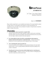
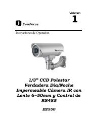
1/3” <strong>CCD</strong> <strong>Polestar</strong> <strong>True</strong><br />
<strong>Day</strong>/<strong>Night</strong> <strong>Weatherproof</strong> <strong>IR</strong><br />
Camera with 6~50mm Lens<br />
and RS485 Control<br />
EZ550<br />
Volume<br />
1
EVERFOCUS ELECTRONICS CORPORATION<br />
P/N: MZ55G00200_Ver. B<br />
Operation Instruction<br />
© 2008 EverFocus Electronics Corp<br />
Please read this manual first for correct installation and operation. This manual should be retained<br />
for future reference. The information in this manual was current when published. The<br />
manufacturer reserves the right to revise and improve its products. All specifications are therefore<br />
subject to change without notice.<br />
All rights reserved. No part of the contents of this manual may be reproduced or transmitted in any<br />
form or by any means without written permission of the EverFocus Electronics Corporation.<br />
2
Precautions<br />
1. Do not place any object on top of the cover.<br />
2. Be careful when handling the camera, do not drop it or subject it to strong shock or<br />
vibration to prevent any damages to it. Do not disassemble it or place it on an unstable<br />
base.<br />
3. Install the camera away from TV, radio transmitter, magnet, electric motor, transformer,<br />
audio speakers because the magnetic fields generate from above devices will distort the<br />
video image.<br />
4. Install the camera away from stoves, or other heat generating devices as the high<br />
temperature could cause deformation, discoloration or other damages of the camera. Install<br />
the camera at where the temperature range will stay between -40°C to 50°C (-40°F to<br />
122°F).<br />
5. Never aim the camera at the sun or other extremely bright objects whether it is in use or<br />
not.<br />
6. Do not touch the surface of <strong>CCD</strong> sensor by hand directly. Use a soft cloth to remove the<br />
dirt from the camera body. Use lens tissue or a cotton tipped applicator and ethanol to<br />
clean the <strong>CCD</strong> sensor and the camera lens. When the camera is not in use, put the cover<br />
cap on the lens mount.<br />
7. All warnings on the products and in the operating instructions should be adhered to.<br />
8. Do not use attachments not recommended by the appliance manufacturer as they may<br />
cause hazards.<br />
9. Do not allow anything to rest on the power cord. Do not locate this appliance where the<br />
cord will be abused by persons walking on it.<br />
10. Do not overload wall outlets and extension cords as this can result in fire or electric shock.<br />
11. Never push objects of any kind into his appliance through cabinet slots as they may touch<br />
dangerous voltage points or short out parts that could result in fire or electric shock.<br />
12. Refer all work related to the installation of this product to qualified service personnel or<br />
system installers.<br />
3
Federal Communication Commission Interference<br />
Statement<br />
This equipment has been tested and found to comply with the limits for a Class B digital device,<br />
pursuant to Part 15 of the FCC Rules. These limits are designed to provide reasonable<br />
protection against harmful interference in a residential installation. This equipment generates,<br />
uses and can radiate radio frequency energy and, if not installed and used in accordance with the<br />
instructions, may cause harmful interference to radio communications. However, there is no<br />
guarantee that interference will not occur in a particular installation. If this equipment does<br />
cause harmful interference to radio or television reception, which can be determined by turning<br />
the equipment off and on, the user is encouraged to try to correct the interference by one of the<br />
following measures:<br />
- Reorient or relocate the receiving antenna.<br />
- Increase the separation between the equipment and receiver.<br />
- Connect the equipment into an outlet on a circuit different from that to which the<br />
receiver is connected.<br />
- Consult the dealer or an experienced radio/TV technician for help.<br />
FCC Caution: Any changes or modifications not expressly approved by the party responsible<br />
for compliance could void the user's authority to operate this equipment.<br />
This device complies with Part 15 of the FCC Rules. Operation is subject to the following two<br />
conditions: (1) This device may not cause harmful interference, and (2) this device must accept<br />
any interference received, including interference that may cause undesired operation.<br />
4
Table of Contents<br />
1.1 Features ....................................................................................................................................... 1<br />
1.2 Accessory Parts List .................................................................................................................... 2<br />
1.3 Specifications ............................................................................................................................... 3<br />
1.4 Dimensions ................................................................................................................................... 4<br />
1.5 Camera Component Description .................................................................................................. 6<br />
1.6 Back Panel Layout ....................................................................................................................... 7<br />
1.7 Related Products .......................................................................................................................... 8<br />
2.1 Wiring and Mounting ................................................................................................................... 13<br />
2.2 Adjusting Camera Position ......................................................................................................... 18<br />
2.3 Adjusting Lens ............................................................................................................................ 19<br />
2.3.1 Lens Setting .................................................................................................................... 19<br />
2.4 Keyboard Connection (Optional) ................................................................................................ 20<br />
3.1 Control Key General Operation Guide........................................................................................ 21<br />
3.2 RS485 ID & Baud Rate Setting ................................................................................................... 23<br />
3.3 OSD Menu Setup ......................................................................................................................... 26<br />
3.3.1 LENS ................................................................................................................................ 26<br />
3.3.2 SHUTTER ........................................................................................................................ 26<br />
3.3.3 WHITE BALANCE control ................................................................................................. 28<br />
3.3.4 BACKLIGHT ..................................................................................................................... 28<br />
3.3.5 AGC (Auto Gain Control) .................................................................................................. 29<br />
3.3.6 DNR (Dynamic Noise Reduction) ..................................................................................... 29<br />
3.3.7 SENS-UP .......................................................................................................................... 30<br />
3.3.8 SPECIAL ........................................................................................................................... 31<br />
3.3.8.1 CAMERA ID ........................................................................................................... 31<br />
3.3.8.2 COLOR ADJ ........................................................................................................... 32<br />
3.3.8.3 SYNC ..................................................................................................................... 33<br />
3.3.8.4 MOTION DETECTION ............................................................................................ 33<br />
3.3.8.5 PRIVACY ............................................................................................................... 35<br />
3.3.8.6 M<strong>IR</strong>ROR ................................................................................................................. 37<br />
3.3.8.7 SHARPNESS .......................................................................................................... 37<br />
3.3.8.8 RESET ................................................................................................................... 38<br />
3.3.8.9 RETURN ................................................................................................................ 38<br />
3.3.9 EXIT ................................................................................................................................. 38<br />
4.1 Key Features with Keyboard ...................................................................................................... 40<br />
4.2 OSD Menu Setting by Keyboard ................................................................................................. 40<br />
4.3 Lens Adjustment by Keyboard ................................................................................................... 41<br />
5
CHAPTER 2 INSTALLATION<br />
CHAPTER 1 PRODUCT OVERVIEW<br />
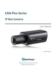
Product Overview<br />
EZ550 camera is a true day/night, long range <strong>IR</strong> bullet style color camera. With <strong>Polestar</strong><br />
sens-up 128x, it offers super sensitivity as 0.002 lux and can capture picture in the<br />
darkness. Engineered with the advanced new generation 16bit DSP, EZ550 has powerful<br />
processing capability to perform super high resolutions. Designed with 3 Axis bracket, you<br />
can position camera at any view angle you like. With built-in DNR (Dynamic Noise<br />
Reduction), the EZ550 camera provides crystal clear images in low light conditions and<br />
70% of substantial disk-saving storage. This bullet style camera supports RS485 remote<br />
control and has an external controller for 6~50mm auto Iris lens and OSD setting.<br />
1.1 Features<br />
• 1/3” SONY Super HAD <strong>CCD</strong> with super high resolution<br />
• Sens-up 128x<br />
• Built-in motor controller for 6~50mm auto Iris lens (zoom and focus)<br />
• 3 Axis Bracket<br />
• <strong>True</strong> <strong>Day</strong>/<strong>Night</strong> feature with <strong>IR</strong> Cut Filter Removable<br />
• OSD setting menu and RS485 remote control<br />
• <strong>IR</strong> distance up to 50 meters (about 164 ft.) and Vari-Frequency <strong>IR</strong> control<br />
• Utilizes the advanced 16-bit Digital Signal Processor (DSP) for crystal clear images<br />
• Built-in DNR (Dynamic Noise Reduction) for noise reduction and 70% saving of disk<br />
storage<br />
• Built-in heater for applications in low temperature environment<br />
• Tamper-proof: cable wires are placed inside the bracket to prevent intentional destruction<br />
• IP66 weatherproof and vandal proof<br />
1<br />
Chapter<br />
1
CHAPTER 2 INSTALLATION<br />
CHAPTER 1 PRODUCT OVERVIEW<br />
1.2 Accessory Parts List<br />
Please be careful when you unpack the box due to the electronics devices inside. Check<br />
and make sure that you have all the items listed below inside the original box:<br />
• Camera Unit x 1<br />
• Waterproof conduit x 1 (connected to the camera bottom)<br />
• Bracket x 1<br />
• Operation Manual x 1<br />
• Mounting kit includes:<br />
-Long Screws x 4 (for mounting bracket)<br />
-Short Screws x 4 (for connecting camera body to bracket)<br />
-Expanding Screws x 4<br />
-Hex key x 1 (for adjusting bracket)<br />
-Hexagon wrench x 1 (for adjusting sunshield)<br />
Please Note: If an item appears to have been damaged in shipment, replace it properly in its<br />
carton and notify the shipper. If any items are missing, notify your EverFocus Electronics Corp.<br />
Sales Representative or Customer Service. The shipping carton is the safest container in which<br />
the unit may be transported. Save it for possible future use.<br />
2
CHAPTER 2 INSTALLATION<br />
CHAPTER 1 PRODUCT OVERVIEW<br />
1.3 Specifications<br />
Items Parameter<br />
Pickup Device 1/3” SONY Super HAD <strong>CCD</strong><br />
Picture Elements 768 x 494 (NTSC) ; 752 x 582 (PAL)<br />
Video Format NTSC or PAL<br />
Scanning System NTSC: 525 TV lines, 60 fields/sec<br />
PAL: 625 TV lines, 50 fields/sec<br />
Horizontal Resolution 560 TVL<br />
Video Output BNC 1.0Vp-p / 75 ohm<br />
Lens Type Vari-focal f=6~50mm<br />
Sensitivity 0.002 Lux/F=1.2 (<strong>IR</strong> Off, SENS-UP 128x)<br />
0 Lux (<strong>IR</strong> On)<br />
Gamma Correction 0.45<br />
S/N Ratio 50 dB<br />
Electronic Shutter 1/50 (1/60) ~1/100,000<br />
<strong>True</strong> <strong>Day</strong>/<strong>Night</strong> Yes<br />
Auto White Balance ATW; AWC; Manual<br />
Black Light Comp. Yes,(OFF; Low ; Mid ; Hi)<br />
Auto Gain Control Yes,(OFF ; Low ; Mid ; Hi)<br />
Digital Noise Reduction Yes,(OFF ; Low ; Mid ; Hi)<br />
Sens-Up 128x, Auto<br />
Sync. Mode Internal; Line lock<br />
<strong>IR</strong> LED Lifespan 20,000 hours<br />
<strong>Weatherproof</strong> IP66<br />
Vandal Resistant Yes<br />
Heater Yes, built-in<br />
Power Source<br />
Power Consumption<br />
2 types: 24VAC<br />
24VAC: 20W max.<br />
Dimensions 115mm(W) x 115mm(H) x 275mm(D) ;<br />
4.5"(W) x 4.5" (H) x 10.8"(D)<br />
Operating Temperature -40°C ~ +50°C ; -40 ℉ ~ 122℉<br />
(20%~80% Humidity)<br />
Weight 2.5 kg ; 5.5 lbs (with bracket)<br />
<strong>IR</strong> Distance 50M / 164 feet<br />
<strong>IR</strong> Wavelength 850nm<br />
Certifications FCC, CE<br />
3
CHAPTER 2 INSTALLATION<br />
CHAPTER 1 PRODUCT OVERVIEW<br />
1.4 Dimensions<br />
Drilling Dimension of holes to holes<br />
Dimension of Bracket<br />
106.5mm/4.19<br />
80mm/3.2”<br />
84mm/3.31”<br />
45mm/1.8”<br />
220.5mm/8.68”<br />
199mm/7.83”<br />
4<br />
112.7mm/4.44
CHAPTER 2 INSTALLATION<br />
Dimension of whole camera with bracket<br />
275mm/10.8”<br />
357mm/14”<br />
5<br />
107.5mm/4.3”<br />
243.5mm/9.74”
CHAPTER 2 INSTALLATION<br />
CHAPTER 1 PRODUCT OVERVIEW<br />
1.5 Camera Component Description<br />
Video output<br />
Sun shield<br />
EZ550 Component description<br />
6<br />
Fixing screw for sunshield<br />
Bracket<br />
Power connector<br />
RS485 terminal<br />
Control key selection switch<br />
Control key
6<br />
1<br />
CHAPTER 2 INSTALLATION<br />
CHAPTER 1 PRODUCT OVERVIEW<br />
1.6 Back Panel Layout<br />
24VAC model (for 24VAC<br />
Power Only)<br />
2<br />
1. Video Output Connector<br />
Connect the video output of the camera to a color monitor or other video devices through<br />
a 75 Ohm type coaxial cable with BNC female connector at backside of the camera.<br />
2. Power Input Terminal<br />
Connect the appropriate power to each model. N/L is used to connect to power in. PE is<br />
a ground pin.<br />
3. RS-485 communication and External <strong>IR</strong> power control pin<br />
12VDC<br />
GND<br />
485+<br />
7<br />
485-<br />
4<br />
3<br />
PIN definition:<br />
a. TXD (RS485 +): for keyboard controlling.<br />
b. RXD (RS485-): for keyboard controlling.<br />
4. Power for <strong>IR</strong> illuminator<br />
Referring to above figure, pin 12VDC and GND are defined as below:<br />
a. GND: Ground<br />
b. 12VDC: provide power source for <strong>IR</strong> illuminator (<strong>IR</strong> illuminator is optional).<br />
5<br />
7<br />
6<br />
1<br />
110V~240VAC model<br />
( Not Available in USA)<br />
7<br />
2<br />
4<br />
3<br />
5
CHAPTER 2 INSTALLATION<br />
5. Control key selection switch<br />
Switch to OSD to control OSD menu by using the control key or switch to LENS to<br />
adjust zooming and focus (please see “2.3.1 Lens setting” and “3. OSD Menu &<br />
Configuration” for details).<br />
Note: when it is connected to RS485 for keyboard control, please switch to OSD,<br />
otherwise it cannot be controlled remotely.<br />
6. Control key<br />
For setting Lens & OSD menu.<br />
7. Cable clips<br />
Used to fix power cable and RS485 cable.<br />
1.7 Related Products<br />
In addition, you may order the following EverFocus products which are recommended for use<br />
with the camera to achieve the best performance:<br />
• EverFocus control keyboard (EKB500)<br />
• <strong>IR</strong> Illuminator and bracket<br />
8
CHAPTER 2 INSTALLATION<br />
Installation<br />
This chapter will describe, in general terms, how to install the EZ550 camera.<br />
STEPS:<br />
1. Wire and mount the camera. See 2.1<br />
2. Adjust the camera position. See 2.2<br />
3. Adjust Lens. See 2.3<br />
4. Connect to Keyboard (Optional) See 2.4<br />
Warning<br />
• To prevent electrical shock, turn off the electrical power before making electrical<br />
connections.<br />
• Do not expose the appliance to water or moisture, nor try to operate it in wet<br />
areas.<br />
2.1 Wiring and Mounting<br />
1. Wire coaxial cable, power cable and RS485 cable through the bracket.<br />
Note: 1. Please use RG59/5C2V coaxial cable without connector<br />
2. Use RS485 cable only if you need to control the camera by a keyboard.<br />
Coaxial cable<br />
Power cable<br />
RS485 cable<br />
13<br />
Chapter<br />
2
CHAPTER 2 INSTALLATION<br />
2. Fix the bracket to wall by using 4 screws.<br />
Coaxial cable<br />
Power cable<br />
RS485 cable<br />
3. Open camera’s back cover: Loose the 2 screws from the back panel cover, then open the<br />
back cover.<br />
14<br />
Screws for back panel
CHAPTER 2 INSTALLATION<br />
4. Take off the cap of waterproof conduit which is at the camera bottom.<br />
Note: 1. the holes of waterproof conduit were plugged, please remove the plug when<br />
you need to use it for connection.<br />
5. Take coaxial cable, power cable and RS485 cable to pass through waterproof conduit,<br />
place them into camera housing.<br />
Note: Do not connect BNC connector to coaxial cable until coaxial cable has passed<br />
through camera housing otherwise your cable might not pass the housing.<br />
15<br />
Power cable (Φ10.3mm)<br />
Coaxial cable<br />
(Φ6mm)<br />
RS485<br />
(Φ5mm)
CHAPTER 2 INSTALLATION<br />
Note: 1. Power cable’s diameter must be less than 10 mm<br />
2. Only use RG59/5C2V for Video cable<br />
3. RS485 cable must be less then 5 mm<br />
6. Close the waterproof cap and fix waterproof conduit to the base of camera firmly.<br />
16<br />
Coaxial cable<br />
Power cable<br />
RS485 cable
CHAPTER 2 INSTALLATION<br />
7. Fix the camera body to bracket by using the 4 shorter screws.<br />
8. Connect RG59 coaxial cable with BNC connector.<br />
9. Unscrew both cable clips, wire power cable and RS485 cable through the cable clips.<br />
Then, screw the cable clips to rear panel.<br />
a. Connecting Power-24VAC model: connect 24VAC power on N and L<br />
100VAC~240VAC Model(not avail USA) : Connect PE, N and L.<br />
*Warning*<br />
• To prevent electrical shock, turn off the electrical power before making electrical<br />
connections.<br />
• Do not connect high voltage power to the camera. It may damage the camera.<br />
• Do not short circuit the power leads and expose the wire when connecting the<br />
power supply to the camera.<br />
b. Connect Video- Make sure connecter is firmly connected.<br />
c. Connecting RS485 (optional): Connect RS585 cable to 485+ and 485-. Please use<br />
screw driver to lose and tight the screw on the RS485 terminal pin when you do<br />
connection.<br />
Power cable<br />
Coaxial cable<br />
Cable Clips<br />
17<br />
RS485 cable<br />
Cable Clips
CHAPTER 2 INSTALLATION<br />
10. Close the back cover and screw the 2 screws firmly. Now, you are done with the<br />
installation.<br />
NOTE: Before you close the cover, please make sure control key is attached firmly and<br />
wire doesn’t stuck.<br />
2.2 Adjusting Camera Position<br />
Adjust camera’s angle vertically or horizontally by using hex key included in package.<br />
18<br />
Screws for back panel<br />
Loose this screw to make<br />
angle adjustment vertically
CHAPTER 2 INSTALLATION<br />
2.3 Adjusting Lens<br />
Open camera’s base, a control key is attached at inner side of the base. Detach the control<br />
key and use this key for OSD or Lens setting.<br />
2.3.1 Lens Setting<br />
Please turn the control key selection switch at the back panel to “Lens”.( ). Use the<br />
control key to do lens setting.<br />
19<br />
Loose this screw to make angle<br />
adjustment horizontally<br />
UP
CHAPTER 2 INSTALLATION<br />
Turn the mini-joystick Up () or Down () to adjust zoom in / zoom out,<br />
Turn the mini-joystick Left () or Right () to adjust focus.<br />
2.4 Keyboard Connection (Optional)<br />
Please refer to Chapter 4 for more details of Keyboard control.<br />
1. Connect the cable from keyboard’s RS485 port to camera’s RS485 port. (Keyboard is<br />
an optional accessory). RS485 connecting accessories are included in <strong>Everfocus</strong><br />
Keyboard package.<br />
2. Connect the cable from video output jack of the camera to monitor’s input jack.<br />
20<br />
Mini-Joystick<br />
UP<br />
The Cursors & the mini-joystick
CHAPTER 2 INSTALLATION<br />
3. EZ550 recognizes EVF-1, EVF-2 and Pelco-D protocols automatically. (No setting is<br />
required)<br />
4. The camera default RS485_ID is 99. BAUD_RATE is 9600. Make sure the key board<br />
camera ID and Baud rate match. For optional changing camera ID and baud rate on<br />
camera, please refer to 3.2.<br />
5. For keyboard setting and operation, please see chapter 4 .<br />
21
CHAPTER 3 OSD MENU AND CONFIGURATION<br />
OSD Menu & Configuration<br />
This chapter introduces how to configure the camera OSD menu.<br />
3.1 Control Key General Operation Guide<br />
Please turn the control key selection switch at the back panel to “OSD” ”( ).<br />
Use the control key to do OSD menu setting.<br />
I. Bring Up the General OSD Menu<br />
Simply press the mini-joystick to bring up the general OSD menu.<br />
II. Bring up the RS485 Setting Menu<br />
Press the mini-joystick and hold for 5 seconds to bring up the RS485 setting menu.<br />
III. Navigate among the OSD Menu Items<br />
Turn the mini-joystick up () or down () to move the cursor up or down.<br />
IV. Change Modes or Setting Parameters<br />
Turn the mini-joystick left () or right () to adjust the mode or parameter of<br />
settings.<br />
V. Switch to Sub-menu Screens<br />
21<br />
Mini-Joystick<br />
Chapter<br />
3<br />
UP<br />
The Cursors & the mini-joystick
CHAPTER 3 OSD MENU AND CONFIGURATION<br />
When the item with sub-menu is selected, press the mini-joystick to switch to the submenu<br />
for further settings. Please refer to the diagram below.<br />
SETUP<br />
> LENS DC
CHAPTER 3 OSD MENU AND CONFIGURATION<br />
3.2 RS485 ID & Baud Rate Setting<br />
Note: This section is optional preserved for the people that want to change camera ID and<br />
baud rate. In most situations, we suggest you can just use Camera ID-99 and Baud Rate-9600,<br />
Protocol-Pelco D on keyboard, then it would work.<br />
I. Please turn the control key selection switch at back panel to “OSD”( ).<br />
II. Press the mini-joystick for 4 seconds until you see the following menu.<br />
A B C D E F G H I J K L M<br />
N O P Q R S T U V W X Y Z<br />
a b c d e f g h i j k l m<br />
n o p q r s t u v w x y z<br />
─ · 0 1 2 3 4 5 6 7 8 9<br />
← → C L R P O S E N D<br />
F I R M W A R E _ V E R _ _ _<br />
III. Turn the mini-joystick up () or down () to adjust setting, press mini-joystick to go next<br />
selection.<br />
IV. Please wait 3 seconds after setting any item, it will automatically switch to next setting item.<br />
V. Camera setting order:<br />
a. Firmware version. VER_xxx- shows the current firmware version.<br />
23
CHAPTER 3 OSD MENU AND CONFIGURATION<br />
A B C D E F G H I J K L M<br />
N O P Q R S T U V W X Y Z<br />
a b c d e f g h i j k l m<br />
n o p q r s t u v w x y z<br />
─ · 0 1 2 3 4 5 6 7 8 9<br />
← → C L R P O S E N D<br />
F I R M W A R E _ V E R _ _ _<br />
b. RS485_ID- adjustable 01~99. Default value is 99. Move joystick RIGHT and LEFT to adjust<br />
it. RS485 ID of EZ550 has to be the same as Keyboard’s CAM ID.<br />
A B C D E F G H I J K L M<br />
N O P Q R S T U V W X Y Z<br />
a b c d e f g h i j k l m<br />
n o p q r s t u v w x y z<br />
─ · 0 1 2 3 4 5 6 7 8 9<br />
← → C L R P O S E N D<br />
R S 4 8 5 I D _ 9 9 _ _ _ _ _<br />
c. BAUD_RATE-adjustable 9600, 4800, 2400 and 1200. Default value is 9600. Move joystick<br />
RIGHT and LEFT to adjust it. Baud rate of EZ550 has to be the same as Keyboard’s baud<br />
rate.<br />
A B C D E F G H I J K L M<br />
N O P Q R S T U V W X Y Z<br />
a b c d e f g h i j k l m<br />
n o p q r s t u v w x y z<br />
─ · 0 1 2 3 4 5 6 7 8 9<br />
← → C L R P O S E N D<br />
B A U D _ R A T E _ 9 6 0 0 _<br />
24
CHAPTER 3 OSD MENU AND CONFIGURATION<br />
d. DATA STORED- Confirm with you that the last 3 settings you have made will be saved.<br />
A B C D E F G H I J K L M<br />
N O P Q R S T U V W X Y Z<br />
a b c d e f g h i j k l m<br />
n o p q r s t u v w x y z<br />
─ · 0 1 2 3 4 5 6 7 8 9<br />
← → C L R P O S E N D<br />
D A T A _ S T O R E D _ _ _ _<br />
e. ENTER_SET_MENU- press the mini-joystick to enter OSD menu setting.<br />
A B C D E F G H I J K L M<br />
N O P Q R S T U V W X Y Z<br />
a b c d e f g h i j k l m<br />
n o p q r s t u v w x y z<br />
─ · 0 1 2 3 4 5 6 7 8 9<br />
← → C L R P O S E N D<br />
E N T E R _ S E T _ M E N U _<br />
Note: For Camera Protocol, EZ550 recognizes EVF-1, EVF-2 and Pelco-D protocols<br />
automatically. (No setting is required)<br />
After setting, it will show an OSD menu, to save setting, go to exit menu and press mini-<br />
joystick.<br />
Note: Camera ID and Baud rate setting can only be performed locally, NOT from<br />
Keyboard.<br />
25
CHAPTER 3 OSD MENU AND CONFIGURATION<br />
3.3 OSD Menu Setup<br />
Please make sure control key selection switch is at OSD position.<br />
Note: Unlike setting Camera ID that requires you to press 3 seconds, OSD menu only<br />
requires one click (less than 1 second) and you should see the following menu.<br />
3.3.1 LENS<br />
1. When the SETUP menu is displayed on the screen, please direct the arrow to point to<br />
“LENS” by turning the mini-joystick UP () or DOWN (). Press the mini-joystick<br />
to adjust <strong>IR</strong>IS level (the higher is brighter). In most cases, you don’t need to adjust this,<br />
since Lens is Auto Iris supported.<br />
SETUP<br />
SETUP<br />
> LENS DC
CHAPTER 3 OSD MENU AND CONFIGURATION<br />
NOTE: Since DC lens is a built-in lens for EZ550 camera, shutter does not support ESC<br />
and Manual functions. ESC and Manual are reserved functions, please do not select these<br />
two options in normal situation.<br />
FLK: Please select “FLK” mode when flickering occurs on the screen, which is<br />
caused by an irregular balance between illumination and frequency. NTSC model:<br />
1/100, PAL model: 1/120.<br />
ESC (Reserved).<br />
Manual (Reserved).<br />
SETUP<br />
SETUP<br />
LENS MANUAL<br />
> SHUTTER FLK<br />
WHITE BAL. ATW<br />
BACKLIGHT OFF<br />
AGC MIDDLE<br />
DNR LOW<br />
SENS-UP ___<br />
SPECIAL SHUTTER ESC
CHAPTER 3 OSD MENU AND CONFIGURATION<br />
3.3.3 WHITE BALANCE control<br />
The screen color can be adjusted by using the WHITE BALANCE function.<br />
1. Please direct the arrow to point to “WHITE BAL” on the SETUP menu by turning<br />
the mini-joystick UP () or DOWN ().<br />
2. Please select the mode you would like to operate by turning the mini- joystick LEFT<br />
() or RIGHT ().<br />
Please select one of the 3 modes below:<br />
ATW (Auto Tracking White Balance): This mode can be used within the color<br />
temperature range from 2,500°K to 8,300°K (eg, fluorescent light, outdoor, sodium<br />
vapor lamp or inside tunnels).<br />
AWC (Auto White Balance Control): Press mini-joystick while the camera is directed<br />
at a piece of white paper to get the optimum state under the present illumination. If<br />
the environment and the light source are changed, you need to adjust the white<br />
balance again.<br />
MANUAL: The manual adjustment mode enables a more precise adjustment. Please<br />
select ATW or AWC first. Then change to manual adjustment mode and press minijoystick.<br />
Set the suitable color temperature, and increase or decrease the red and blue<br />
color values at the same time while checking the color changes of the object.<br />
NOTE:<br />
SETUP<br />
LENS DC WHITE BAL. MANUAL
CHAPTER 3 OSD MENU AND CONFIGURATION<br />
2. Select the mode you would like to operate by turning the mini-joystick LEFT () or<br />
RIGHT ().<br />
SETUP<br />
LENS DC BACKLIGHT OFF<br />
AGC MIDDLE<br />
DNR LOW<br />
SENS-UP AUTO
CHAPTER 3 OSD MENU AND CONFIGURATION<br />
As the level of gain changes, the background noise in the low light level automatically<br />
decreases.<br />
1. Please direct the arrow to point to “DNR” on the SETUP menu by turning the minijoystick<br />
UP () or DOWN ().<br />
2. Select the mode you would like to operate by turning the mini-joystick LEFT () or<br />
RIGHT ().<br />
SETUP<br />
LENS DC DNR LOW<br />
SENS-UP AUTO
CHAPTER 3 OSD MENU AND CONFIGURATION<br />
3. Press the mini-joystick when you finish all the settings.<br />
NOTE:<br />
○1 The maximum storage magnification in low light level movement situations can be<br />
adjusted by pressing the mini-joystick in “AUTO” mode.<br />
○2 The screen becomes brighter when the magnification increases; yet the after image<br />
increases as well.<br />
○3 Please be noted that spots and noise may appear if storage magnification increases when<br />
SENS-UP is operating. This is a normal phenomenon.<br />
3.3.8 SPECIAL<br />
1. Please direct the arrow to point to “SPECIAL” on the SETUP menu by turning the<br />
mini-joystick UP () or DOWN ().<br />
SETUP<br />
LENS DC
CHAPTER 3 OSD MENU AND CONFIGURATION<br />
3) Press the mini-joystick.<br />
4) Maximum 15 letters can be used for the ID.<br />
Turning the mini-joystick UP (), DOWN (), LEFT () or RIGHT () to select<br />
the letters.<br />
Press the mini-joystick to lock in the letters.<br />
5) Once a name has been selected, please choose a position where you would like to<br />
display the name.<br />
Move the cursor onto “POS” and press the mini-joystick.<br />
The name will appear at the top left hand corner.<br />
Please use the 4 directional buttons to find the desired position to display the name.<br />
6) If you would like to cancel the ID inputted, please move the cursor to “CLR”, and all<br />
the letters inputted will be deleted.<br />
7) Select “END” and press the mini-joystick to complete ID input.<br />
SPECIAL<br />
> CAMERA ID ON<br />
COLOR ADJ.
CHAPTER 3 OSD MENU AND CONFIGURATION<br />
3.3.8.3 SYNC<br />
There are two SYNCHRONIZATION modes: INTERNAL and EXTERNAL LINE-<br />
LOCK. In LINE-LOCK mode, without a synchronous generator, it synchronizes the<br />
video signal between cameras. The Line-Lock synchronization is only used in the places of<br />
60Hz (NTSC models) or 50Hz (PAL models).<br />
-INT: Internal synchronization<br />
-LL: External line-lock synchronization<br />
=> If you choose “LL”, you can adjust the phase your wish to set. Then press the minijoystick.<br />
You can adjust the phase you wish to set from 0 to 359.<br />
SPECIAL<br />
CAMERA ID OFF<br />
COLOR ADJ. SYNC. LL
CHAPTER 3 OSD MENU AND CONFIGURATION<br />
Additionally, it is possible to change the position of the area. Please refer to the<br />
following example for detailed steps on moving AREA1 to center.<br />
1. The original position of AREA1 was TOP: 10, DOWN: 25, LEFT: 20 and RIGHT:<br />
40.<br />
AREA1<br />
2. Increase DOWN scale value by 20. AREA1 position after change is: TOP: 10,<br />
DOWN: 45, LEFT: 20 and RIGHT: 40.<br />
AREA1<br />
AREA1 AREA2<br />
AREA3 AREA4<br />
3. Increase TOP scale value by 20. AREA1 position after change is: TOP: 30, DOWN:<br />
45, LEFT: 20 and RIGHT: 40.<br />
AREA1<br />
34
CHAPTER 3 OSD MENU AND CONFIGURATION<br />
4. Increase RIGHT scale value by 20. AREA1 position after change is: TOP: 30,<br />
DOWN: 45, LEFT: 20 and RIGHT: 60.<br />
AREA1<br />
5. Increase LEFT scale value by 20. AREA1 position after change is: TOP: 30, DOWN:<br />
45, LEFT: 40 and RIGHT: 60.<br />
In order to save the changes and complete the setting, press the mini-joystick. This<br />
allows you to return to the previous menu.<br />
3.3.8.5 PRIVACY<br />
This mode covers the areas you do not want to see on the screen.<br />
1) Please direct the arrow to point to “PRIVACY” by turning the mini-joystick UP<br />
() or DOWN ().<br />
2) Select “ON” by turning the mini-joystick LEFT () or RIGHT ().<br />
3) Press the mini-joystick.<br />
SPECIAL<br />
AREA1<br />
CAMERA ID OFF<br />
COLOR ADJ. PRIVACY ON
CHAPTER 3 OSD MENU AND CONFIGURATION<br />
Please turn the mini-joystick LEFT () or RIGHT () to adjust the value for size<br />
of the area to be covered.<br />
Additionally, it is possible to change the position of the area to be covered.<br />
Please refer to the following example for detailed steps on moving AREA1 to<br />
center.<br />
1. The original position of AREA1 was TOP: 10, DOWN: 25, LEFT: 20 and RIGHT:<br />
40.<br />
AREA1<br />
2. Increase DOWN scale value by 20. AREA1 position after change is: TOP: 10,<br />
DOWN: 45, LEFT: 20 and RIGHT: 40.<br />
AREA1<br />
AREA1 AREA2<br />
AREA3 AREA4<br />
3. Increase TOP scale value by 20. AREA1 position after change is: TOP: 30, DOWN:<br />
45, LEFT: 20 and RIGHT: 40.<br />
AREA1<br />
36
CHAPTER 3 OSD MENU AND CONFIGURATION<br />
4. Increase RIGHT scale value by 20. AREA1 position after change is: TOP: 30,<br />
DOWN: 45, LEFT: 20 and RIGHT: 60.<br />
AREA1<br />
5. Increase LEFT scale value by 20. AREA1 position after change is: TOP: 30, DOWN:<br />
45, LEFT: 40 and RIGHT: 60.<br />
In order to save the changes and complete the setting, press the mini-joystick.<br />
This allows you to return to the previous menu.<br />
3.3.8.6 M<strong>IR</strong>ROR<br />
-ON: Sets a horizontal image 180 angel inversion.<br />
-OFF: Disable the inversion.<br />
SPECIAL<br />
AREA1<br />
CAMERA ID OFF<br />
COLOR ADJ. M<strong>IR</strong>ROR OFF<br />
SHARPNESS ON
CHAPTER 3 OSD MENU AND CONFIGURATION<br />
-OFF: Disable the SHARPNESS mode.<br />
Please press the mini-joystick.<br />
The available range of level is 0~31.<br />
SPECIAL<br />
CAMERA ID OFF<br />
COLOR ADJ. SHARPNESS ON
CHAPTER 3 OSD MENU AND CONFIGURATION<br />
39
CHAPTER 4 CONTROL FROM KEYBOARD<br />
Control from Keyboard<br />
EKB500 (Optional)<br />
Note!<br />
Before being able to control keyboard, make sure Keyboard RS485 camera ID, Baud rate<br />
match the camera. (see COM port setting in EKB500 manual). EZ550 camera ID default<br />
is 99. Baud rate is 9600. Support Protocol EVF-1, EVF-2 and Pelco-D.<br />
4.1 Key Features with Keyboard<br />
1. OSD can be set up from Keyboard.<br />
2. Lens Zoom and Focus can be controlled by keyboard.<br />
4.2 OSD Menu Setting by Keyboard<br />
a. Press “Menu” to enter SETUP menu.<br />
b. Move the joystick UP () and DOWN (). This allows you to move between<br />
selection items in setup menu.<br />
c. If the item has sub-menu setting (sign ), press “Menu” again to display the<br />
sub-menu.<br />
SETUP<br />
> LENS DC
CHAPTER 4 CONTROL FROM KEYBOARD<br />
d. Move the joystick RIGHT () and LEFT () to adjust the mode and parameters<br />
of the selected item.<br />
e. Press “Menu” to leave and goes to previous menu after setting. Move to “exit” and<br />
press “menu” button when you finish all settings.<br />
f. For detail setting and every setup function, Please refer to “3.3. OSD Menu Setup”.<br />
4.3 Lens Adjustment by Keyboard<br />
1. Press Zoom in or Zoom out to adjust zoom or Turn Joystick clockwise to zoom out.<br />
Counterclockwise to zoom in.<br />
2. Press Focus N or Focus F to adjust focus.<br />
3. Press Iris + and Iris – to adjust Iris.<br />
41
CHAPTER 4 CONTROL FROM KEYBOARD<br />
Head Office:<br />
12F, No.79 Sec. 1 Shin-Tai Wu Road,<br />
Hsi-Chih, Taipei, Taiwan<br />
TEL: +886-2-26982334<br />
FAX: +886-2-26982380<br />
www.everfocus.com.tw<br />
USA L.A. Office:<br />
1801 Highland Ave. Unit A<br />
Duarte, CA 91010, U.S.A.<br />
TEL: +1-626-844-8888<br />
FAX: +1-626-844-8838<br />
www.everfocus.com<br />
USA N.Y. Office:<br />
415 Oser Avenue Unit S<br />
Hauppauge, NY 11788<br />
TEL: 631-436-5070<br />
FAX: 631-436-5027<br />
www.everfocus.com<br />
Your EverFocus product is designed and<br />
manufactured with high quality materials<br />
and components which can be recycled and<br />
reused.<br />
This symbol means that electrical and<br />
electronic equipment, at their end-of-life,<br />
should be disposed of separately from your<br />
household waste.<br />
Please, dispose of this equipment at your<br />
local community waste collection/recycling<br />
centre.<br />
In the European Union there are separate<br />
collection systems for used electrical and<br />
electronic product.<br />
Please, help us to conserve the environment<br />
we live in!<br />
42<br />
Europe Office:<br />
Albert-Einstein-Strasse 1<br />
D-46446 Emmerich, Germany<br />
TEL: +49-2822-9394-0<br />
www.everfocus.de<br />
China Office:<br />
Room 609, Technology Trade Building,<br />
Shangdi Information Industry Base, Haidian<br />
District, Beijing,China 10085<br />
TEL: +86-10-62973336/37/38/39<br />
FAX: +86-10-62971423<br />
www.everfocus.com.cn<br />
Japan Office:<br />
1809 WBG MARIBU East 18F,<br />
2-6 Nakase.Mihama-ku.<br />
Chiba city 261-7118, Japan<br />
TEL: +81-43-212-8188<br />
FAX: +81-43-297-0081<br />
www.everfocus.com<br />
Ihr EverFocus Produkt wurde entwickelt und<br />
hergestellt mit qualitativ hochwertigen<br />
Materialien und Komponenten, die recycelt<br />
und wieder verwendet werden können.<br />
Dieses Symbol bedeutet, dass elektrische und<br />
elektronische Geräte am Ende ihrer<br />
Nutzungsdauer vom Hausmüll getrennt<br />
entsorgt werden sollen.<br />
Bitte entsorgen Sie dieses Gerät bei Ihrer<br />
örtlichen kommunalen Sammelstelle oder im<br />
Recycling Centre.<br />
Helfen Sie uns bitte, die Umwelt zu erhalten,<br />
in der wir leben!