NAV IP Access Controller - Everfocus
NAV IP Access Controller - Everfocus
NAV IP Access Controller - Everfocus

Create successful ePaper yourself
Turn your PDF publications into a flip-book with our unique Google optimized e-Paper software.
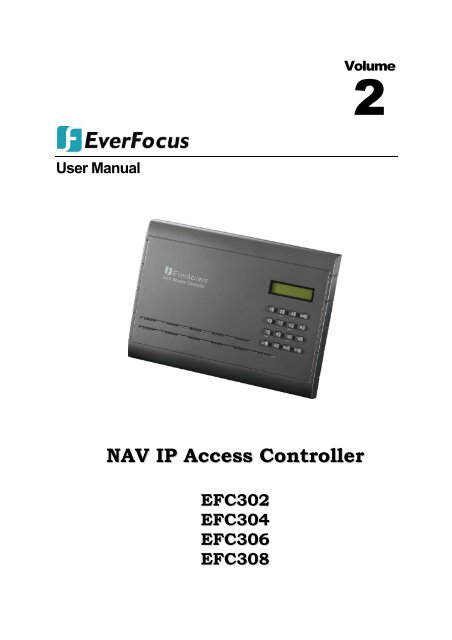
User Manual<br />
<strong>NAV</strong> <strong>IP</strong> <strong>Access</strong> <strong>Controller</strong><br />
EFC302<br />
EFC304<br />
EFC306<br />
EFC308<br />
Volume<br />
2
EVERFOCUS ELECTRONICS CORPORATION<br />
EFC302<br />
EFC304<br />
EFC306<br />
EFC308<br />
User Manual<br />
2009~2011 EverFocus Electronics Corp<br />
All rights reserved. No part of the contents of this manual may be reproduced or transmitted in any form or by<br />
any means without written permission of the EverFocus Electronics Corporation.
Contents<br />
I<br />
<strong>NAV</strong> <strong>IP</strong> <strong>Access</strong> controller<br />
1. Introduction ...................................................................................................................... 1<br />
1.1 Features ......................................................................................................................... 2<br />
1.2 Overview ...................................................................................................................... 3<br />
1.3 Specification ................................................................................................................. 4<br />
1.4 Packing List ...................................................................................................................... 6<br />
1.5 Optional Device ............................................................................................................... 6<br />
1.6 Definitions of Terminal Block and LEDs .......................................................................... 7<br />
1.6.1 Terminal Block and LEDs on Main Module ..................................................................................... 7<br />
1.6.2 Terminal Block and LEDs on Alarm Module .................................................................................... 8<br />
1.6.3 Terminal Block and LEDs on Door Module ...................................................................................... 9<br />
2. Installation ...................................................................................................................... 11<br />
2.1 Installation Preparation ............................................................................................. 11<br />
2.1.1 Obtain a Floor Plan ........................................................................................................................ 11<br />
2.1.2 Determine the Hardware and Location ........................................................................................ 12<br />
2.1.3 Determine the Number of <strong>Controller</strong>s/ Modules According to System Structure ............................ 13<br />
2.2 Hardware Installation ................................................................................................. 13<br />
2.2.1 Mounting the Enclosure (Optional) and <strong>Controller</strong> ...................................................................... 13<br />
2.2.2 Installing and Connecting the Readers .......................................................................................... 17<br />
2.2.3 Connecting to the Door Lock, Sensor and Open Button ............................................................... 18<br />
2.2.4 Connecting to the Fire Alarm/ Alarm Input................................................................................... 20<br />
2.2.5 Connecting to the Fire Alarm/ Alarm Output ................................................................................ 21<br />
2.2.6 Connecting to the Computer through the Network ..................................................................... 22<br />
2.2.7 Mounting a Backup Battery in the Enclosure (Optional) .............................................................. 22<br />
3. System Architecture and Connections ............................................................................ 23<br />
3.1 Small System for 8 Doors ............................................................................................. 23<br />
3.2 System for 256 Doors ................................................................................................... 23<br />
3.3 System for More theN 256 Doors ................................................................................ 24<br />
3.4 RS485 Bus Extension .................................................................................................... 24<br />
4. Starting Up the <strong>Controller</strong> ........................................................................................... 26<br />
4.1 Connecting to Power .................................................................................................... 26<br />
4.2 Restoring the <strong>Controller</strong> ............................................................................................... 26<br />
4.3 Before First Use ............................................................................................................. 27<br />
5. <strong>Controller</strong> Configuration and Operation ......................................................................... 28<br />
5.1 General Operation Guideline ........................................................................................ 28<br />
5.2 Home Screen ................................................................................................................. 28<br />
5.3 Direct Operations from Keypad .................................................................................... 29<br />
5.3.1 Enter System Configuration .............................................................................................................. 29<br />
5.3.2 Enter Arm/Disarm Menu .................................................................................................................. 29
II<br />
<strong>NAV</strong> <strong>IP</strong> <strong>Access</strong> controller<br />
5.3.3 Display Firmware Version ................................................................................................................. 29<br />
5.3.4 Display the Number of Installed Modules ........................................................................................ 30<br />
5.3.5 Display the Current Card and Event Number ................................................................................... 30<br />
5.3.6 Display the <strong>Controller</strong> <strong>IP</strong> Address ..................................................................................................... 30<br />
5.4 Level One System Configuration Items ......................................................................... 30<br />
5.5 System Setting .............................................................................................................. 31<br />
5.5.1 Enter System Setting Menu .............................................................................................................. 31<br />
5.5.2 Set Date Format ................................................................................................................................ 31<br />
5.5.3 Set Date ............................................................................................................................................ 31<br />
5.5.4 Set Time ............................................................................................................................................ 32<br />
5.5.5 Auto Daylight Saving Time ................................................................................................................ 32<br />
5.5.6 Set System PIN .................................................................................................................................. 32<br />
5.5.7 Set Arm PIN ...................................................................................................................................... 33<br />
5.5.8 Set Language .................................................................................................................................... 33<br />
5.5.9 Backlight Setting ............................................................................................................................... 33<br />
5.5.10 System Maintanence ...................................................................................................................... 33<br />
5.5.11 Erase All Events .............................................................................................................................. 35<br />
5.5.12 Load Factory Default ...................................................................................................................... 35<br />
5.6 Card Setting ................................................................................................................... 35<br />
5.6.1 Enter Card Setting Menu .................................................................................................................. 35<br />
5.6.2 Add Cards ......................................................................................................................................... 36<br />
5.6.3 Delete Cards ..................................................................................................................................... 36<br />
5.6.4 Set Card Properties ........................................................................................................................... 37<br />
5.6.5 Show Card Number .......................................................................................................................... 40<br />
5.7 Door Setting .................................................................................................................. 40<br />
5.7.1 Enter Door Setting Menu .................................................................................................................. 40<br />
5.7.2 Schedule Switch Setting ................................................................................................................... 40<br />
5.7.3 Door <strong>Access</strong> Mode ............................................................................................................................ 41<br />
5.7.4 Open Time Setting ............................................................................................................................ 42<br />
5.7.5 Over TimeSetting .............................................................................................................................. 42<br />
5.8 Reader Setting ............................................................................................................... 43<br />
5.8.1 Enter Reader Setting Menu .............................................................................................................. 43<br />
5.8.2 System Reader Setting ...................................................................................................................... 43<br />
5.8.3 Keypad Setting .................................................................................................................................. 43<br />
5.8.4 Reader to Door Allocation ................................................................................................................ 44<br />
5.8.5 Reader Backlight Setting ................................................................................................................... 44<br />
5.8.6 Set Reader LED or LCD format .......................................................................................................... 44<br />
5.8.7 Set Card Format ................................................................................................................................ 45<br />
5.9 Alarm Setting ................................................................................................................ 45<br />
5.9.1 Components for Alarm ..................................................................................................................... 46<br />
5.9.2 Alarm Configuration Basics ............................................................................................................... 46<br />
5.9.3 Enter Alarm Setting Menu ................................................................................................................ 46<br />
5.9.4 Alarm Setting Menu Structure .......................................................................................................... 47<br />
5.9.5 Alarm Input Setting .......................................................................................................................... 47<br />
5.9.6 ALarm Event Setting ......................................................................................................................... 51<br />
5.10 Network Setting .......................................................................................................... 56<br />
5.10.1 DHCP Setting................................................................................................................................... 56<br />
5.10.2 Set <strong>IP</strong> Address ................................................................................................................................. 57<br />
5.11 Address Setting ........................................................................................................... 57<br />
5.12 Arm/Disarm ................................................................................................................. 58<br />
5.12.1 Arm the Systemusing the <strong>Controller</strong> Keypad ................................................................................. 58
III<br />
<strong>NAV</strong> <strong>IP</strong> <strong>Access</strong> controller<br />
5.12.2 Disarm the Systemusing the <strong>Controller</strong> Keypad ............................................................................. 58<br />
5.12.3 Reset Alarm .................................................................................................................................... 59<br />
5.12.4 Arm/Disarm the Systemusing aKeypad Reader .............................................................................. 59<br />
5.12.5 Arm/Disarm the Systemusing aLCDReader .................................................................................... 60<br />
5.13 Use Reader as Keypad ................................................................................................. 60<br />
6. Software Introduction ................................................................................................... 62<br />
6.1 Main Feature ................................................................................................................. 62<br />
6.2 Hightlight Performance Overview ................................................................................ 62<br />
6.3 Baseon TCP/<strong>IP</strong> <strong>Access</strong> Conttrol System Architecture ................................................... 63<br />
7. Start to Use ..................................................................................................................... 64<br />
7.1 Quick Start..................................................................................................................... 64<br />
7.1.1 Add and Configure <strong>Controller</strong> ........................................................................................................... 64<br />
Set <strong>Access</strong> Rule .......................................................................................................................................... 64<br />
7.1.3 A Varietyof WaystoAdd Cards .......................................................................................................... 66<br />
7.1.4 Setup Departemnt and Cardholder .................................................................................................. 67<br />
7.1.5 Configuration and Attendance ......................................................................................................... 67<br />
7.1.6 Real‐time Monitoring ....................................................................................................................... 68<br />
7.1.7 Export Function ................................................................................................................................ 68<br />
7.1.8 Print Function ................................................................................................................................... 70<br />
7.2 Login .............................................................................................................................. 70<br />
7.3 Familiar with the Browser Page .................................................................................... 71<br />
7.3.1 Main Page Introduction .................................................................................................................... 71<br />
7.3.2 Menus ............................................................................................................................................... 72<br />
7.3.3 Control Pannel .................................................................................................................................. 72<br />
7.3.4 Real‐time Monitoring ....................................................................................................................... 74<br />
7.3.5 System Event Record ........................................................................................................................ 74<br />
8. Basic Setting ................................................................................................................... 77<br />
8.1 Change Password .......................................................................................................... 77<br />
8.2 Set User Group and User .............................................................................................. 78<br />
8.3 User Group .................................................................................................................... 80<br />
8.3.1 Add A Group ..................................................................................................................................... 80<br />
8.3.2 Edit A Group ..................................................................................................................................... 80<br />
8.3.3 Delete A Group ................................................................................................................................. 80<br />
8.4 User Setting ................................................................................................................... 81<br />
8.4.1 Add A User ........................................................................................................................................ 81<br />
8.4.2 EditA User ......................................................................................................................................... 82<br />
8.4.3 Delete A User .................................................................................................................................... 82<br />
8.4.4 Export Users ..................................................................................................................................... 82<br />
8.4.5 Print Users ........................................................................................................................................ 82<br />
8.4.6 Search Users ..................................................................................................................................... 83<br />
8.5 Local Server ................................................................................................................... 83<br />
8.6 System Upgrade ............................................................................................................ 84<br />
8.6.1 Upgrade Online ................................................................................................................................ 84<br />
8.6.2 Upgrade Local ................................................................................................................................... 84<br />
9. Cardholder ...................................................................................................................... 85<br />
9.1 Department Setting ...................................................................................................... 85
IV<br />
<strong>NAV</strong> <strong>IP</strong> <strong>Access</strong> controller<br />
9.1.1 Add A Department ............................................................................................................................ 85<br />
9.1.2 Edit A Department ............................................................................................................................ 86<br />
9.1.3 Delete A Department ....................................................................................................................... 86<br />
9.2 Cardholder Setting ........................................................................................................ 87<br />
9.2.1 Add ACardholder .............................................................................................................................. 87<br />
9.2.2 EditA Cardholder .............................................................................................................................. 91<br />
9.2.3 Delete A Cardholder ......................................................................................................................... 92<br />
9.2.4 Export CardHolders .......................................................................................................................... 92<br />
9.2.5 PrintCardHolders .............................................................................................................................. 92<br />
9.2.6 Search CardHolders .......................................................................................................................... 92<br />
9.3 ImportCardholders ........................................................................................................ 92<br />
10. Real‐time Monitoring .................................................................................................. 94<br />
10.1 Real‐time Event ........................................................................................................... 94<br />
10.1.1 Remote <strong>Controller</strong> .......................................................................................................................... 95<br />
10.1.2 Remote Dvr and View ..................................................................................................................... 95<br />
10.2 Edit Electronic Map ..................................................................................................... 95<br />
10.2.1 Add An Electronic Map ................................................................................................................... 95<br />
10.2.2 Edit An Electronic Map ................................................................................................................... 96<br />
10.2.3 Delete An Electronic Map ............................................................................................................... 97<br />
10.3 Report ......................................................................................................................... 97<br />
10.3.1 Search Cardholders ........................................................................................................................ 97<br />
10.3.2 Export Cardholders ......................................................................................................................... 97<br />
10.3.3 Print Cardholders ............................................................................................................................ 98<br />
11. Maintenance ............................................................................................................... 99<br />
11.1 Backup ......................................................................................................................... 99<br />
11.1.1 Manual Backup ............................................................................................................................... 99<br />
11.1.2 Auto Backup ................................................................................................................................. 100<br />
11.2 Restore ...................................................................................................................... 101<br />
11.2.1 Restore from a FTP Server ............................................................................................................ 101<br />
11.2.2 Restore from Local Computer ...................................................................................................... 101<br />
11.3 PurgeOut‐of‐date Data ............................................................................................. 102<br />
12. <strong>Controller</strong> ................................................................................................................... 103<br />
12.1 <strong>Controller</strong> Setting ...................................................................................................... 103<br />
12.1.1 Add A <strong>Controller</strong> ........................................................................................................................... 103<br />
12.1.2 Edit A <strong>Controller</strong> ........................................................................................................................... 104<br />
12.1.3 Delete A <strong>Controller</strong> ....................................................................................................................... 105<br />
12.1.4 Refresh ......................................................................................................................................... 105<br />
12.1.5 Setting .......................................................................................................................................... 105<br />
12.1.6 Export <strong>Controller</strong>s ......................................................................................................................... 113<br />
12.1.7 Print <strong>Controller</strong>s ........................................................................................................................... 114<br />
12.1.8 Download Data to <strong>Controller</strong> ....................................................................................................... 114<br />
13. <strong>Access</strong> Rule ................................................................................................................ 115<br />
13.1 Date Type .................................................................................................................. 115<br />
13.1.1 AddA Date .................................................................................................................................... 115<br />
13.1.2 Delete A Date ............................................................................................................................... 116<br />
13.2 Group Schedule ......................................................................................................... 116<br />
13.2.1 Add A Group Schedule .................................................................................................................. 117
V<br />
<strong>NAV</strong> <strong>IP</strong> <strong>Access</strong> controller<br />
13.2.2 Delete A Group Schedule ............................................................................................................. 117<br />
13.2.3 Edit A Group Schedule .................................................................................................................. 117<br />
13.2.4 Save As A New Schedule ............................................................................................................... 119<br />
13.3 <strong>Access</strong> Group ............................................................................................................ 119<br />
13.3.1 Add A <strong>Access</strong> Group ..................................................................................................................... 119<br />
13.3.2 Delete A <strong>Access</strong> Group ................................................................................................................. 120<br />
13.4 Door Schedule ........................................................................................................... 120<br />
13.4.1 Add A Door Schedule .................................................................................................................... 120<br />
13.4.2 Delete A Door Schedule ................................................................................................................ 121<br />
13.4.3 Edit A Door Schedule .................................................................................................................... 121<br />
13.4.4 Save As A New Schedule ............................................................................................................... 122<br />
13.5 <strong>Access</strong> Door ............................................................................................................... 122<br />
14. Card ........................................................................................................................... 123<br />
14.1 Card Type Setting ...................................................................................................... 123<br />
14.2 Card Setting ............................................................................................................... 124<br />
14.2.1 AddA (Batch) Card ........................................................................................................................ 124<br />
14.2.2 EditA (Batch) Card ........................................................................................................................ 126<br />
14.2.3 Delete A (Batch) Card ................................................................................................................... 126<br />
14.2.4 Export Cards ................................................................................................................................. 126<br />
14.2.5 Print Cards .................................................................................................................................... 126<br />
14.2.6 Search Cards ................................................................................................................................. 127<br />
14.3 Import Cards ............................................................................................................. 127<br />
15. Report ........................................................................................................................ 129<br />
15.1 CardReport ................................................................................................................ 129<br />
15.1.1 Search Cards ................................................................................................................................. 129<br />
15.1.2 Export Cards ................................................................................................................................. 129<br />
15.1.3 Print Cards .................................................................................................................................... 129<br />
15.2 Card‐dependent Event .............................................................................................. 130<br />
15.2.1 Search Events ............................................................................................................................... 130<br />
15.2.2 Export Events ................................................................................................................................ 130<br />
15.2.3 Print Events .................................................................................................................................. 130<br />
15.3 Card‐independent Event ........................................................................................... 130<br />
15.3.1 Search Events ............................................................................................................................... 131<br />
15.3.2 Export Events ................................................................................................................................ 131<br />
15.3.3 Print Events .................................................................................................................................. 131<br />
16. Attendance Basic Setting ........................................................................................... 132<br />
16.1 Attendance Time ....................................................................................................... 132<br />
16.1.1 Edit Attendance Time ................................................................................................................... 133<br />
16.1.2 Search Attendance Time .............................................................................................................. 133<br />
16.1.3 Export Attendance Time ............................................................................................................... 133<br />
16.1.4 PrintAttendance Time .................................................................................................................. 133<br />
16.2 Week Holiday Setting ................................................................................................ 134<br />
16.2.1 Edit AWeek Holiday ...................................................................................................................... 134<br />
16.2.2 SearchWeek Holidays ................................................................................................................... 134<br />
16.2.3 Export Week Holidays .................................................................................................................. 135<br />
16.2.4 Print Week Holidays ..................................................................................................................... 135<br />
16.3 Special Holiday Setting .............................................................................................. 135
VI<br />
<strong>NAV</strong> <strong>IP</strong> <strong>Access</strong> controller<br />
16.3.1 Add A SpecialHoliday .................................................................................................................... 135<br />
16.3.2 EditA SpecialHoliday ..................................................................................................................... 136<br />
16.3.3 RemoveA SpecialHoliday .............................................................................................................. 136<br />
16.3.4 SearchSpecialHolidays .................................................................................................................. 136<br />
16.3.5 ExportSpecialHolidays .................................................................................................................. 136<br />
16.3.6 PrintSpecialHolidays ..................................................................................................................... 137<br />
17. Attendance Exception ............................................................................................... 138<br />
17.1 No‐<strong>Access</strong>‐Attendance .............................................................................................. 138<br />
17.1.1 AddA No‐<strong>Access</strong>‐Attendance ........................................................................................................ 138<br />
17.1.2 EditA No‐<strong>Access</strong>‐Attendance ........................................................................................................ 139<br />
17.1.3 DeleteA No‐<strong>Access</strong>‐Attendance ................................................................................................... 139<br />
17.1.4 SearchNo‐<strong>Access</strong>‐Attendance ...................................................................................................... 139<br />
17.1.5 ExportNo‐<strong>Access</strong>‐Attendance ....................................................................................................... 140<br />
17.1.6 PrintNo‐<strong>Access</strong>‐Attendance ......................................................................................................... 140<br />
17.2 Time‐off Enroll .......................................................................................................... 140<br />
17.2.1 AddTime‐off Enroll ....................................................................................................................... 141<br />
17.2.2 EditTime‐off Enroll ........................................................................................................................ 141<br />
17.2.3 DeleteTime‐off Enroll ................................................................................................................... 142<br />
17.2.4 Search Time‐off Enroll .................................................................................................................. 142<br />
17.2.5 ExportTime‐off Enroll ................................................................................................................... 143<br />
17.2.6 PrintTime‐off Enroll ...................................................................................................................... 143<br />
17.3 Overtime Enroll ......................................................................................................... 143<br />
17.3.1 Add Overtime Enroll ..................................................................................................................... 143<br />
17.3.2 Edit Overtime Enroll ..................................................................................................................... 144<br />
17.3.3 DeleteOvertime Enroll .................................................................................................................. 145<br />
17.3.4 SearchOvertime Enroll .................................................................................................................. 145<br />
17.3.5 ExportOvertime Enroll .................................................................................................................. 145<br />
17.3.6 PrintOvertime Enroll ..................................................................................................................... 145
<strong>NAV</strong> <strong>IP</strong> <strong>Access</strong> controller<br />
Federal Communication Commission Interference<br />
Statement<br />
This equipment has been tested and found to comply with the limits for a Class B digital device, pursuant<br />
to Part 15 of the FCC Rules. These limits are designed to provide reasonable protection against harmful<br />
interference in a residential installation. This equipment generates, uses and can radiate radio frequency<br />
energy and, if not installed and used in accordance with the instructions, may cause harmful<br />
interference to radio communications. However, there is no guarantee that interference will not occur in<br />
a particular installation. If this equipment does cause harmful interference to radio or television<br />
reception, which can be determined by turning the equipment off and on, the user is encouraged to try<br />
to correct the interference by one of the following measures:<br />
‐ Reorient or relocate the receiving antenna.<br />
‐ Increase the separation between the equipment and receiver.<br />
‐ Connect the equipment into an outlet on a circuit different from that to which the<br />
receiver is connected.<br />
‐ Consult the dealer or an experienced radio/TV technician for help.<br />
FCC Caution: Any changes or modifications not expressly approved by the party responsible for<br />
compliance could void the user's authority to operate this equipment.<br />
This device complies with Part 15 of the FCC Rules. Operation is subject to the following two conditions:<br />
(1) This device may not cause harmful interference, and (2) this device must accept any interference<br />
received, including interference that may cause undesired operation.
<strong>NAV</strong> <strong>IP</strong> <strong>Access</strong> controller<br />
1. Introduction<br />
The <strong>NAV</strong> <strong>IP</strong> access controller is a powerful Linux‐based controller with modular design. You can<br />
add up to 4 door modules to the <strong>NAV</strong> controller for expanding the control scale of up to 8<br />
doors / readers. Or you can add one alarm module to the <strong>NAV</strong> controller to manage up to 10<br />
alarm inputs and 18 alarm outputs.<br />
Moreover, each <strong>NAV</strong> controller can connect up to 31 EverFocus’ Flex series controllers to<br />
expand the control scale of up to 256 doors / readers. You can connect to the <strong>NAV</strong> controller<br />
via network to remotely review, monitor all the events on <strong>NAV</strong> and Flex controllers and<br />
configure all 31 Flex series controllers from the same built‐in browser‐based management<br />
software. Furthermore, you can optionally install multiple <strong>NAV</strong> controllers for a larger scale<br />
access control system. By doing so, you will need the enterprise level Navigation software<br />
installed as a central server to manage the large access control system.<br />
Figure 1‐1<br />
The following table lists the models of <strong>NAV</strong> <strong>IP</strong> access controllers along with the supported<br />
number of doors, readers and alarm inputs / outputs. A description for the supported<br />
modules and devices is also provided below.<br />
1<br />
Chapter<br />
1
<strong>NAV</strong> <strong>IP</strong> <strong>Access</strong> <strong>Controller</strong>s<br />
Model Name Description<br />
EFC302<br />
EFC304<br />
EFC306<br />
EFC308<br />
Optional Devices / Modules<br />
Name Description<br />
Door Module<br />
Alarm Module<br />
Flex Series<br />
<strong>Controller</strong><br />
1.1 Features<br />
Supports 2 doors, 2 readers<br />
Supports 2 alarm inputs, 4 alarm outputs<br />
Supports 4 doors, 4 readers<br />
Supports 4 alarm inputs, 6 alarm outputs<br />
Supports 6 doors, 6 readers<br />
Supports 6 alarm inputs, 8 alarm outputs<br />
Supports 8 doors, 8 readers<br />
Supports 8 alarm inputs, 10 alarm outputs<br />
Embedded Linux operating system<br />
Built‐in database engine<br />
Built‐in 512M large‐capacity memory<br />
2<br />
<strong>NAV</strong> <strong>IP</strong> <strong>Access</strong> controller<br />
Each <strong>NAV</strong> controller can add up to 4 door modules. Each door module<br />
controls up to 2 readers, 2 relays for door locks, 2 relays for alarm<br />
outputs, other door control peripherals, and event signals to the main<br />
d l<br />
Each <strong>NAV</strong> controller can add only one alarm module. The alarm module<br />
can connect up to 8 alarm inputs and 8 alarm outputs.<br />
Each <strong>NAV</strong> controller can connect up to 31 Flex series controllers. Each<br />
Flex series can connect up to 8 doors and 8 readers.<br />
Modular design for easy expansion of the system, and auto‐detection on expansion<br />
modules<br />
Manage up to 31 EverFocus’ Flex Series controllers<br />
Secure access through the Web browser is guaranteed by SSL (Secure Socket Layer)<br />
Network automatic backup and upgrade<br />
USB2.0 automatic backup and controller firmware upgrade<br />
Remote setting, control and management; no software needed to be installed<br />
Manage up to 100,000 cards and 1,000,000 event records<br />
Supports 2,048 management groups<br />
Supports 2,048 access schedule<br />
Supports 12 kinds of access pattern<br />
Supports card / group mode to access the door
<strong>NAV</strong> <strong>IP</strong> <strong>Access</strong> controller<br />
Supports 4 x 4 lock level, achieves 4 teams x 4 multi cards access setting on each<br />
door<br />
Each door supports 10 different independent day setting (Sunday to Monday, and 3<br />
kinds of custom day setting). Each day can take 10 time zones with minimum 1<br />
minute duration<br />
Supports comprehensive access features including interlock, area‐based anti<br />
passback, multi‐card / multi‐level access control, panic open, remote door control,<br />
system arm / disarm, multiple door verification mode, and first card, etc.<br />
Multiple languages support: English, Chinese and Russian<br />
1.2 Overview<br />
The diagram below illustrates the controller along with its main components and functions.<br />
Main Module<br />
Figure 1‐2<br />
The main module controls the fundamental functions of the controller, including the<br />
built‐in browser‐based software, the system management, the power supply, event<br />
records, built‐in Ethernet port, and communication via RS‐485 port, two alarm inputs and<br />
two alarm outputs. The main module also controls the door modules and alarm module.<br />
No. Name Description<br />
3
1 NetworkPort Connects to the network.<br />
2 LCD Screen<br />
4<br />
<strong>NAV</strong> <strong>IP</strong> <strong>Access</strong> controller<br />
Displays the current status of the controller and the<br />
menu.<br />
3 Keypad Provides an interface to operate the controller.<br />
4 USB2.0 Port For database backup / restore and firmware upgrade.<br />
5 Terminal Block<br />
6 LEDs<br />
Alarm Module<br />
Connects to power, alarm input / output devices, etc.<br />
Please refer to 1.6.1 Terminal Block and LEDs on Main<br />
Module.<br />
Indicates the controller status. Please refer to 1.6.1<br />
Terminal Block and LEDs on Main Module.<br />
The alarm module is used to extend the controller’s alarm function, adding up to 8 alarm<br />
inputs and 8 alarm outputs. Each controller can only add one alarm module.<br />
No. Name Description<br />
7 LEDs<br />
8 Terminal Block<br />
Door Module<br />
Indicates the alarm status. Please refer to 1.6.2 Terminal<br />
Block and LEDs on Alarm Module.<br />
Connects to alarm input / output devices. Please refer to<br />
1.6.2 Terminal Block and LEDs on Alarm Module.<br />
The door module is used to control up to 2 readers, 2 relays for door locks, 2 relays for<br />
alarm outputs, other door control peripherals, and event signals to the main module.<br />
Each controller can add up to 4 door modules.<br />
No. Name Description<br />
9 LEDs<br />
Indicates the door module status. Please refer to 1.6.3<br />
Terminal Block and LEDs on Door Module.<br />
10 Terminal Block<br />
1.3 Specification<br />
System<br />
Connects to door sensors, door locks, request‐to‐exit<br />
devices and alarm outputs. Please refer to 1.6.3<br />
Terminal Block and LEDs on Door Module.<br />
Operating System Linux embedded<br />
Database Built‐in<br />
Memory 512M<br />
Management Software Built‐in browser‐based software, EFS2000, ENS2000
<strong>NAV</strong> <strong>IP</strong> <strong>Access</strong> controller<br />
Built‐in Software<br />
Operation<br />
Maximum Card Amount 100,000<br />
Maximum Even Records 1,000,000<br />
Supporting Readers 2 (expandable up to 8)<br />
Supporting Door Control 2 (expandable up to 8)<br />
Max. Flex <strong>Controller</strong>s<br />
Connected via RS‐485<br />
Up to 31 controllers<br />
Reader Communication Format Wiegand26 / RS‐232<br />
Card / System PIN 8 digits<br />
Alarm PIN 8 digits<br />
Alarm Input<br />
Supports system management, device configuration,<br />
live event list view and map view, CCTV integration<br />
2 (expandable to 10, each alarm input can be set as<br />
firmware alarm or regular alarm.)<br />
Alarm Output<br />
2 alarm outputs on main module, 2 alarm outputs on<br />
each door module and 8 alarm outputs on alarm<br />
Network Interface<br />
d l<br />
100M adaptive Ethernet interface<br />
Baud Rate 9600 bps<br />
Programmable Duration Maximum 10 per day with minimum duration of 1 min.<br />
Programmable Date<br />
<strong>Access</strong> Group 2,048<br />
<strong>Access</strong> Schedule 2,048<br />
Door <strong>Access</strong> Verification 12 modes<br />
Other Functions Support<br />
Mechanical<br />
LCD Display Screen<br />
Buzzer Built‐in<br />
Keypad 4 x 4 key<br />
General<br />
Current for Door Control Relay 5A (Max.)<br />
Sunday to Saturday and 3 customized date types on<br />
each individual door.<br />
Supports multiple doors interlock, card expiration,<br />
anti‐passback, backup battery connection, backup<br />
battery charger, real‐time clock and 4 x 4 lock level<br />
(achieves 4 teams x 4 multi cards access setting on<br />
2 × 9(for Chinese / Russian characters),<br />
2 x 18(for English characters)<br />
Current for Alarm Relay 2A (Max.)<br />
Power Supply DC11V ~ 16V (DC 15V when backup battery is<br />
Maximum Current 2A<br />
Dimension (L x W x H) 300 × 216 × 33 mm / 11.8 x 8.5 x 1.3 in<br />
5
Temperature 14°F~122°F<br />
Humidity
<strong>NAV</strong> <strong>IP</strong> <strong>Access</strong> controller<br />
1.6 Definitions of Terminal Block and LEDs<br />
1.6.1 Terminal Block and LEDs on Main Module<br />
Terminal Block Definitions<br />
Figure 1‐3<br />
No Terminal Name Function No. Terminal Name Function<br />
1 Alarm In 0 General alarm input 0 10 RS485_A Signal A of RS‐485 bus<br />
2 GND Alarm input GND 11 COMM_GND GND of RS‐485<br />
3 FireIn Fire alarm input 12 RS485_B Signal B of RS‐485 bus<br />
4 AUXAlarmOutNo<br />
5 AUXAlarmOutCom<br />
6 AUXAlarmOutNC<br />
7 AUXAlarmOutNo<br />
8 AUXAlarmOutCom<br />
9 AUXAlarmOutNC<br />
Normally open pin of<br />
auxiliary alarm output<br />
Common pin of<br />
auxiliary alarm output<br />
Normally close pin of<br />
auxiliary alarm output<br />
Normally open pin of<br />
main alarm output<br />
Common pin of main<br />
alarm output<br />
Normally close pin of<br />
main alarm output<br />
Figure 1‐4<br />
7<br />
13 Power Power input<br />
14 GND Power GND<br />
15 BATT+ Battery positive pin<br />
16 BATT‐ Battery negative pin<br />
17 USB USB port<br />
18 Ethernet Ethernet port
LED Definitions<br />
No Description No Description<br />
1<br />
2<br />
The power is on when the light<br />
is on.<br />
The fire alarm is triggered<br />
when the light is on.<br />
1.6.2 Terminal Block and LEDs on Alarm Module<br />
3<br />
4<br />
The data is received when the light<br />
is on.<br />
The data is transmitted when the<br />
light is on.<br />
Figure 1‐5<br />
8<br />
<strong>NAV</strong> <strong>IP</strong> <strong>Access</strong> controller<br />
No Terminal<br />
Name<br />
Function<br />
No<br />
.<br />
Terminal<br />
Name<br />
Function<br />
1 Alarm1_In Alarm signal input 1 19 Alarm5_In Alarm signal input 5<br />
2 GND GND 20 GND GND<br />
3 Alarm2_In Alarm signal input 2 21 Alarm6_In Alarm signal input 6<br />
4 Alarm3_In Alarm signal input 3 22 Alarm7_In Alarm signal input 7<br />
5 GND GND 23 GND GND<br />
6 Alarm4_In Alarm signal input 4 24 Alarm8_In Alarm signal input 8<br />
7 Alarm1_NO Alarm 1 output for NO 25 Alarm5_NO Alarm 5 output for NO<br />
8 Alarm1_COM<br />
Alarm 1 output in<br />
common<br />
26 Alarm5_COM<br />
9 Alarm1_NC Alarm 1 output for NC 27 Alarm5_NC<br />
Alarm 5 output in<br />
common<br />
Alarm 5 output for<br />
normally‐close<br />
10 Alarm2_ NO Alarm 2 output for NO 28 Alarm6_ NO Alarm 6 output for NO<br />
11 Alarm2_ COM<br />
Alarm 2 output in<br />
common<br />
29 Alarm6_ COM<br />
Alarm 6 output in<br />
common<br />
12 Alarm2_ NC Alarm 2 output for NC 30 Alarm6_ NC Alarm 6 output for NC<br />
13 Alarm3_ NO Alarm 3 output for NO 31 Alarm7_ NO Alarm 7 output for NO<br />
14 Alarm3_ COM<br />
Alarm 3 output in<br />
common<br />
32 Alarm7_ COM<br />
Alarm 7 output in<br />
common<br />
15 Alarm3_ NC Alarm 3 output for NC 33 Alarm7_ NC Alarm 7 output for NC<br />
16 Alarm4_ NO Alarm 4 output for NO 34 Alarm8_ NO Alarm 8 output for NO
<strong>NAV</strong> <strong>IP</strong> <strong>Access</strong> controller<br />
17 Alarm4_ COM<br />
Alarm 4 output in<br />
common<br />
9<br />
35 Alarm8_ COM<br />
Alarm 8 output in<br />
common<br />
18 Alarm4_ NC Alarm 4 output for NC 36 Alarm8_ NC Alarm 8 output for NC<br />
LED Definitions<br />
Figure 1‐6<br />
No Description No Description<br />
1 Alarm 1 5 Alarm 5<br />
2 Alarm 2 6 Alarm 6<br />
3 Alarm 3 7 Alarm 7<br />
4 Alarm 4 8 Alarm 8<br />
1.6.3 Terminal Block and LEDs on Door Module<br />
Figure 1‐7<br />
No Terminal Name Function No. Terminal Name Function<br />
1 Reader1_Data0 Reader 1 Wiegand Data 0 17 Reader2_Data0 Reader 2 Wiegand Data 0<br />
2 Reader1_Data1 Reader 1 Wiegand Data 1 18 Reader2_Data1 Reader 2 Wiegand Data 1<br />
3 Reader1_DC Power supply for reader 1 19 Reader2_DC Power supply for Reader<br />
4 Reader1_GND GND for the Reader 1 20 Reader2_GND GND for the Reader 2<br />
5 Reader1_Ctrl Control line for reader 1 21 Reader2_Ctrl Control line for Reader 2<br />
6 RX_1<br />
7 TX_1<br />
Port to TX signal to reader<br />
1<br />
Port to RX signal from<br />
reader 1<br />
22 RX_2<br />
23 TX_2<br />
Port to TX signal to<br />
Reader 2<br />
Port to RX signal from<br />
Rader 2
8 Door1_ Button<br />
The request‐to‐exit<br />
button for Door 1<br />
10<br />
24 Door2_ Button<br />
<strong>NAV</strong> <strong>IP</strong> <strong>Access</strong> controller<br />
The request‐to‐exit<br />
button for Door 2<br />
9 Door1_GND GND for terminal 8 & 10 25 Door2_GND GND for terminal 24 & 26<br />
10 Door1_ Sensor<br />
11 Door1_NO<br />
12 Door1_COM<br />
13 Door1_NC<br />
14 Alarm1_NO<br />
15 Alarm1_COM<br />
16 Alarm1_NC<br />
LED Definitions<br />
Door sensor input for<br />
Door 1<br />
Normally open pin for<br />
door control relay 1<br />
Common pin for door<br />
control relay 1<br />
Normally close pin for<br />
door control relay 1<br />
Normally open pin for<br />
alarm output relay 1<br />
Common pin for alarm<br />
output relay 1<br />
Normally close pin for<br />
alarm output relay 1<br />
Figure 1‐8<br />
26 Door2_ Sensor<br />
27 Door2_NO<br />
28 Door2_COM<br />
29 Door2_NC<br />
30 Alarm2_NO<br />
31 Alarm2_COM<br />
32 Alarm2_NC<br />
No Description No Description<br />
1<br />
Indicates the alarm relay #2 is<br />
energized.<br />
5<br />
Indicates the alarm relay #1 is<br />
energized.<br />
Door sensor input for<br />
Door 2<br />
Normally open pin for<br />
door control relay 2<br />
Common pin for door<br />
control relay 2<br />
Normally close pin for<br />
door control relay 2<br />
Normally open pin for<br />
alarm output relay 2<br />
Common pin for alarm<br />
output relay 2<br />
Normally close pin for<br />
alarm output relay 2<br />
2 Indicates the reader #2 is connected. 6 Indicates the reader #1 is connected.<br />
3<br />
4<br />
Indicates the door sensor #2 is off<br />
(the door’s open).<br />
Indicates the door control relay #2 is<br />
energized.<br />
7<br />
8<br />
Indicates the door sensor #1 is off (the<br />
door’s open).<br />
Indicates the door control relay #1 is<br />
energized.
<strong>NAV</strong> <strong>IP</strong> <strong>Access</strong> controller<br />
2. Installation<br />
The Installation has three procedures described as below. Each procedure will be<br />
introduced in the following sections in detail.<br />
Step 1: Installation Preparation<br />
Obtain a floor plan<br />
Determine the hardware and location<br />
Determine the number of controllers according to<br />
system structure<br />
Step 3: Software Setup / Configuration<br />
2.1 Installation Preparation<br />
Step 2: Hardware Installation<br />
Log in controller built‐in software through IE on computer<br />
Set user account for user software<br />
Set controller and other equipment<br />
Set holidays, shifts and door control rules<br />
Log in card and set card attributes<br />
Before installation, users are advised to collect information properly which will make the<br />
installation more smoothly and helps to reduce time and energy cost. For professional<br />
constructors, the information below will be of great use.<br />
2.1.1 Obtain a Floor Plan<br />
Obtain a floor plan of the building in which the access control system is to be installed.<br />
11<br />
Chapter<br />
2<br />
Installing the controller<br />
Connecting to the door lock / open button / sensor / bell<br />
Connecting to the alarm input / output<br />
Connecting to the card reader<br />
Connecting to the computer through the networkMount a<br />
backup battery in the enclosure
12<br />
<strong>NAV</strong> <strong>IP</strong> <strong>Access</strong> controller<br />
Obtaining a floor plan helps the installer determine what components need to be<br />
installed, and where. It also is essential in determining the length of cable needed to<br />
connect readers to the controller. A floor plan can be a blue print of the building, a<br />
design, or simply a drawing of the facility. Any document showing the footprint of the<br />
building can be used. The dimensions are important to note, especially when<br />
determining cable lengths. A floor plan may be obtained from your local city hall.<br />
2.1.2 Determine the Hardware and Location<br />
Determine which hardware to use and where it will be installed. This is the most crucial<br />
step in the preparation stage. First, determine how many access points, or doors, need to<br />
be managed by the access control system. These access points will control the security of<br />
the facility, and can limit the entry and exit to and from any given area of the building.<br />
After deciding which doors need to be controlled, the user must also determine the level<br />
of security needed at each door. There are many ways to manage each door, using<br />
different resources. These resources include, but are not limited to: proximity readers,<br />
mag strip readers, relays, and request to exits. A few common door configurations are<br />
described below:<br />
One Set of <strong>NAV</strong> <strong>Controller</strong>+ One Reader – The Basic Door Entry Control<br />
The most basic configuration involves one <strong>NAV</strong> controller, a reader and an electric strike. In<br />
this configuration, a person presents a card to the reader, and is either granted or denied<br />
access. The electric strike unlocks if the system grants access. Another variation of this<br />
scenario involves setting the system up to monitor whether the door is open, which allows<br />
the system to protect against propped open doors, or doors being held open for too long.<br />
One Set of <strong>NAV</strong> <strong>Controller</strong>+ One Reader + One Door Open Button – Control of Exit<br />
Adding a door open button to the above scenario allows the system to control when to<br />
allow people to exit through a door. The door open button equipment includes a button<br />
which has to be pressed when a card holder exits, or a door sensor. The equipment should<br />
be arranged on the secure side of the door.<br />
Figure 2‐1
<strong>NAV</strong> <strong>IP</strong> <strong>Access</strong> controller<br />
One Set of <strong>NAV</strong> <strong>Controller</strong>+ Two Readers – Control of both Entry and Exit<br />
When the security grade is relatively high or the administrator requires the card holders to<br />
get in or out at fixed time or date through specific door, two sets of EFC301 are needed.<br />
Additional installation of one set of EFC301 on the side of the door requires the card<br />
holders to swipe the card when exiting and entering. This rule has more reliable security<br />
regarding who can enter and who can exit and the administrator canal so master the entry<br />
and exit time of card holders.<br />
2.1.3 Determine the Number of <strong>Controller</strong>s/ Modules According to System Structure<br />
Determine how many controllers / modules and network interface are required.<br />
1. Each <strong>NAV</strong> controller can accommodate up to 8 readers. If the system to be installed<br />
requires more than 8 readers, additional controllers are necessary. E.g. Flex series<br />
controllers.<br />
2. If one or more controllers are installed at a different location, then the system<br />
computer is to be installed, and an Ethernet interface is required to connect over the<br />
internet. An Ethernet interface may also be used in locations at which the controllers<br />
are installed a long distance away from the system computer. Software is required to<br />
manage these <strong>NAV</strong> controllers.<br />
2.2 Hardware Installation<br />
After the preparation work is finished, user can start installation. This chapter mainly<br />
introduces how to install the hardware part, which is divided into six steps:<br />
1. Mounting the enclosure (optional) and controller.<br />
2. Installing and connecting the readers.<br />
3. Connecting to door lock, sensor and open button.<br />
4. Connecting to the alarm input / output.<br />
5. Connecting to the computer.<br />
6. Mounting a backup battery in the enclosure (optional).<br />
2.2.1 Mounting the Enclosure (Optional) and <strong>Controller</strong><br />
The <strong>NAV</strong> controller should be installed in an easily‐accessible position. However, it<br />
should be noticed that the controller is the core part of the entire system and can be<br />
used to change database. After the installation site is selected, a relative secure clean<br />
position in which the administrator is easy to operate should be selected.<br />
Due to the controller is an essential part of the access control system. It is recommended<br />
to mount the <strong>NAV</strong> controller in a metal enclosure (EPN‐871‐B). If you are using the<br />
enclosure, additional AC power supply is required. The enclosure uses a 24V AC power<br />
supply with a built‐in 15V DC converter.<br />
If the system requires additional door or alarm modules, install them in the controller<br />
before mounting the controller in the enclosure or on the wall.<br />
13
14<br />
<strong>NAV</strong> <strong>IP</strong> <strong>Access</strong> controller<br />
Note: If the screw holes of the controller do not line up properly with the enclosure,<br />
some filling may be required for adjustment.<br />
1. Use the supplied mounting template to position the holes for the support frames and<br />
then mount the two support frames on a wall.<br />
Figure 2‐2<br />
Note: If using the metal enclosure, use the four pre‐drilled holes on the back wall of<br />
the enclosure and then mount the two support frames on the interior of the<br />
enclosure.<br />
2. Mount the controller base board to the support frames.<br />
Figure 2‐3<br />
a. Place the controller base board on the support frames. Line up the four latches<br />
on the support frames with the holes on the controller base board. Once lined up,<br />
slide the controller base board down to secure it in place.<br />
b. Secure the controller base board to the support frames using the supplied two<br />
screws.
<strong>NAV</strong> <strong>IP</strong> <strong>Access</strong> controller<br />
3. Install and mount additional door modules or the alarm module.<br />
Note: The controller can hook up to 4 door modules and only 1 alarm module. Each<br />
door module is cascaded to its left side module till the main module. The door<br />
modules and the alarm module can be placed in any sequence.<br />
a. Connect the pins on the lower right corner of the new module to the connector<br />
on the bottom left corner of the installed module. Make sure that the pins fit<br />
snugly into the receiving module.<br />
Figure 2‐4<br />
b. Secure the module to the controller base board using the three screws provided<br />
in the module package.<br />
The Reader / Door Index Conversion<br />
Figure 2‐5<br />
15
16<br />
<strong>NAV</strong> <strong>IP</strong> <strong>Access</strong> controller<br />
The index conversion of readers is displayed as below. The readers / doors are<br />
counted 1 to 8 from right to left.<br />
Figure 2‐6<br />
4. Placing back the cover of controller.<br />
a. The cover has two latches on the interior of the top horizontal edge. Place these<br />
latches in the corresponding holes on the top horizontal edge of the controller<br />
base board.<br />
Figure 2‐7<br />
b. Once the latches are in place, the bottom portion of the cover will fit easily over<br />
the rest of the controller base board.<br />
c. Secure the cover to the controller base board along the exterior of the<br />
horizontal bottom edge.
<strong>NAV</strong> <strong>IP</strong> <strong>Access</strong> controller<br />
Figure 2‐8<br />
2.2.2 Installing and Connecting the Readers<br />
The readers must be mounted near each door and connected directly to the door<br />
module(s) in the controller. Each door module can control up to two readers. The<br />
supported reader formats are Wiegand and RS‐232.<br />
RS‐232 Connection<br />
Connect the RS‐232 wires from the reader to the terminal block on the door module. You<br />
can either connect the wires from the reader to Pin 3 ~ 7 (Door 1) or Pin 19 ~ 23 (Door 2)<br />
on the terminal block.<br />
19<br />
20<br />
21<br />
22<br />
23<br />
3<br />
4<br />
5<br />
6<br />
7<br />
Door module<br />
+12V<br />
GND<br />
Reader Ctrl<br />
RX<br />
TX<br />
Red<br />
Black<br />
Yellow<br />
Blue<br />
Gray<br />
Figure 2‐7<br />
Wiegand Connection<br />
Connect the Wiegand wires from the reader to the terminal block on the door module.<br />
You can either connect the wires from the reader to Pin 1 ~ 5 (Door 1) or Pin 17 ~ 21<br />
(Door 2) on the terminal block.<br />
17<br />
1<br />
4<br />
G H I<br />
7<br />
PQRS<br />
*<br />
2<br />
A B C<br />
5<br />
J K L<br />
8<br />
T U V<br />
Ever<strong>Access</strong><br />
0<br />
3<br />
D E F<br />
6<br />
M N O<br />
9<br />
WXYZ<br />
#
17<br />
18<br />
19<br />
20<br />
21<br />
1<br />
2<br />
3<br />
4<br />
5<br />
Door module<br />
Reader_Data0<br />
Reader_Data1<br />
+12V<br />
GND<br />
Reader Ctrl<br />
Green<br />
Brown<br />
Red<br />
Black<br />
Yellow<br />
Figure 2‐8<br />
18<br />
<strong>NAV</strong> <strong>IP</strong> <strong>Access</strong> controller<br />
Each door module can provide +12V voltage for two readers. Twisted cable is<br />
recommended to connect the controller and readers. The maximum transmission<br />
distance between the reader and controller depends on the gauge of the cable and the<br />
specification of the reader. Please read the reader user manual carefully before installing<br />
the cable for the readers.<br />
Note: It is strongly recommended to use one connection format in a multi‐reader system,<br />
i.e. all the readers are connected to the door modules through RS‐232 or Wiegand<br />
connection. Multiple connection formats could cause compatibility problems to the<br />
system.<br />
2.2.3 Connecting to the Door Lock, Sensor and Open Button<br />
Ever <strong>Access</strong><br />
Connecting to the Door Lock<br />
The Electric strikes and magnetic locks are used to keep doors locked unless the system<br />
grants access or the user sets the doors to remain unlocked. One strike or magnetic lock<br />
is required for each door. These locks must be powered separately from the readers. The<br />
mounting instructions for strikes and magnetic locks vary depending on the<br />
manufacturer and type of lock. Please consult the instructions included with the door<br />
hardware when installing. Once the locks are installed, follow the instructions below to<br />
connect them to the controller.<br />
Electric Strike<br />
Connect the wires from the electric strike to the terminal block on the door module.<br />
You can either connect the wires to Pin 11 and 12 (Door 1) or Pin 27 and 28 (Door 2)<br />
on the terminal block.<br />
1<br />
4<br />
G H I<br />
7<br />
PQRS<br />
*<br />
2<br />
A B C<br />
5<br />
J K L<br />
8<br />
T U V<br />
0<br />
3<br />
D E F<br />
6<br />
M N O<br />
9<br />
WXYZ<br />
#
<strong>NAV</strong> <strong>IP</strong> <strong>Access</strong> controller<br />
Figure 2‐9<br />
Magnetic Lock<br />
Connect the wires from the magnetic lock to the terminal block on the door module.<br />
You can either connect the wires to Pin 12 and 13 (Door 1) or Pin 28 and 29 (Door 2)<br />
on the terminal block.<br />
Note:<br />
28<br />
29<br />
27<br />
28<br />
Door module<br />
Door module<br />
12<br />
13<br />
Figure 2‐10<br />
1. The maximum current output of the door lock relay is 5A. If the current of the<br />
door lock is over this value, an external power relay will be required.<br />
2. When using a DC power source to power the lock, connect the positive lead to<br />
V+. When using an AC power source, the leads are interchangeable.<br />
Connecting to the Door Sensor<br />
Connect the wires from the door sensor to the terminal block on the door module. You<br />
can either connect the wires to Pin 9 and 10 (Door 1) or Pin 25 and 26 (Door 2) on the<br />
terminal block.<br />
25<br />
26<br />
11<br />
12<br />
Door module<br />
COM<br />
9<br />
10<br />
COM<br />
V-<br />
N.C.<br />
19<br />
N.O.<br />
V+<br />
V- V+<br />
GND<br />
Input Signal<br />
Door sensor
Figure 2‐11<br />
20<br />
<strong>NAV</strong> <strong>IP</strong> <strong>Access</strong> controller<br />
Connecting to the Door Open Button<br />
Connect the wires from the door open button to the terminal block on the door module.<br />
You can either connect the wires to Pin 8 and 9 (Door 1) or Pin 24 and 25 (Door 2) on the<br />
terminal block.<br />
24<br />
25<br />
Door module<br />
8<br />
9<br />
Input Signal<br />
Figure 2‐12<br />
2.2.4 Connecting to the Fire Alarm/ Alarm Input<br />
You can either connect the alarm inputs to the main module or the alarm module.<br />
On the Main Module<br />
The main module provides two general alarm inputs, connecting to Pin 1 and 2 or Pin<br />
2 and 3 on the terminal block. The GND terminal is shared by these two input signals.<br />
Both inputs can be configured as either fire alarm input or general alarm input.<br />
Figure 2‐13<br />
EXIT<br />
On the Alarm Module<br />
The alarm modules provide 8 alarm inputs. The alarm input pins provided by the<br />
alarm module includes Pin 1, 3, 4, 6, 19, 21, 22, 24. For details on pin assignment,<br />
please refer to 1.6.2 Terminal Block and LEDs on Alarm Module. Following is an<br />
example on connecting the alarm input to the alarm module.<br />
GND
<strong>NAV</strong> <strong>IP</strong> <strong>Access</strong> controller<br />
Alarm module<br />
Figure 2‐14<br />
2.2.5 Connecting to the Fire Alarm/ Alarm Output<br />
The alarm modules provide 8 alarm outputs. You can assign the corresponding relay<br />
status to the different events. There are three terminals: COM, NO and NC. The wiring<br />
depends on the alarm device. Please read the user manual of the external alarm devices<br />
before wiring. Following are examples on connecting the alarm output to the alarm<br />
module. For details on pin assignment, please refer to 1.6.2 Terminal Block and LEDs on<br />
Alarm Module.<br />
7<br />
8<br />
Alarm module<br />
8<br />
9<br />
Alarm module<br />
1<br />
2<br />
N.O.<br />
COM<br />
N.C.<br />
Figure 2‐15<br />
COM<br />
Figure 2‐16<br />
21<br />
Alarm input<br />
GND<br />
N.O. terminal<br />
C. terminal<br />
C. terminal<br />
N.C. terminal<br />
Alarm sensor<br />
Alarm Device<br />
Alarm<br />
Device
22<br />
<strong>NAV</strong> <strong>IP</strong> <strong>Access</strong> controller<br />
2.2.6 Connecting to the Computer through the Network<br />
User can carry out basic setting through the keypad on the EFC301 controller or<br />
connection with the computer via TCP/<strong>IP</strong>. User can carry complicated system<br />
administration by accessing the embedded system in the controller through various<br />
browsers.<br />
TCP/<strong>IP</strong><br />
Figure 2‐17<br />
2.2.7 Mounting a Backup Battery in the Enclosure (Optional)<br />
You can optionally connect a backup battery in the enclosure to provide backup power to<br />
the controller. Once the battery is installed, it will charge off the external power until it is<br />
needed, at which time it will automatically be used to power the system.<br />
Connecting to the Backup Battery<br />
Connect the wires from the backup battery to the terminal block on the main module.<br />
Connect the positive lead to Pin 15 and negative lead to Pin 16 on the terminal block of<br />
the main module.<br />
Figure 2‐18<br />
If a backup battery is connected, the controller will automatically switch to backup power<br />
in the event that the external power is lost. The backup battery will charge while external<br />
power is being supplied.<br />
In general, the larger the battery capacity, the longer it can support the controller. A<br />
12AH battery can provide 4 hours of energy for a controller containing 4 door modules,<br />
one alarm module and 8 readers.<br />
Ever<strong>Access</strong><br />
FlexII<strong>Access</strong> <strong>Controller</strong><br />
3 ARM<br />
ABC DEF<br />
GHI JKL MNO<br />
PQR S TUV WXYZ<br />
2 1<br />
4 5 6<br />
7 8 9<br />
CLR 0<br />
ENT SYS<br />
Nav <strong>Controller</strong>
<strong>NAV</strong> <strong>IP</strong> <strong>Access</strong> controller<br />
3. System Architecture and Connections<br />
Ever<strong>Access</strong>® <strong>NAV</strong> <strong>Controller</strong> runs the embedded Linux and includes the built‐in browser‐based<br />
management software. No dedicated computer needs to be running to capture and store the events.<br />
Users can access and manage the controller or the system from any computer on the network.<br />
This chapter introduces the 3 types of system architectures in order of system scale. Additionally, the<br />
RS485 Bus extension is introduced for extending more door controls with Ever<strong>Access</strong> Flex controllers.<br />
3.1 Small System for 8 Doors<br />
As introduced in chapter 1, <strong>NAV</strong> <strong>Controller</strong> provides a flexible, modulated installation up to 8 doors or<br />
readers directly. No additional controller or computer needed.<br />
The network settings can be configured directly from the LCD and keypad on the controller. As long as<br />
the network settings are correct, users can access it by typing the controller <strong>IP</strong> address in the browser<br />
from a computer on the network. The built‐in browser based software will provide the full<br />
comprehensive functions to manage and monitor the system.<br />
3.2 System for 256 Doors<br />
Figure 3‐1 Connecting the <strong>Controller</strong> to a PC<br />
Each <strong>NAV</strong> <strong>Controller</strong> can connect and control up to 31 Ever<strong>Access</strong> Flex controllers via RS485 bus. Each<br />
Flex controller can hook up to 8 doors/readers, so total 256 doors/readers can be controlled under the<br />
architecture of one <strong>NAV</strong> <strong>Controller</strong> plus 31 Flex controllers.<br />
Users can connect to the <strong>NAV</strong> <strong>Controller</strong> via a computer to remotely review, and monitor all the events<br />
on <strong>NAV</strong> and Flex controllers. Users can also all 31 Flex controllers from the browser‐based management<br />
software.<br />
The system structure is illustrated in the below figure:<br />
23<br />
TCP/<strong>IP</strong><br />
Ever<strong>Access</strong><br />
F le x I I A cc es s C o n tr o ller<br />
Chapter<br />
3<br />
3 ARM<br />
ABC DEF<br />
GHI JKL MNO<br />
PQR S TUV WXYZ<br />
2 1<br />
4 5 6<br />
7 8 9<br />
CLR 0<br />
ENT SYS<br />
Nav <strong>Controller</strong>
Ever<strong>Access</strong><br />
Fle x I I A cc es s C o n tr o ller<br />
1 2 3 ARM<br />
ABC DEF<br />
4 5 6<br />
GHI JKL MNO<br />
7 8 9<br />
PQRS TUV WXYZ<br />
CL R 0 ENT<br />
SYS<br />
Figure 3‐2 System Structure for 256 doors<br />
3.3 System for More theN 256 Doors<br />
24<br />
<strong>NAV</strong> <strong>IP</strong> <strong>Access</strong> controller<br />
Each <strong>NAV</strong> <strong>Controller</strong> can control up to 31 Flex controllers. And multiple <strong>NAV</strong> <strong>Controller</strong>s can be<br />
controlled and communicate with a Navigation software central server. Navigation software is the<br />
enterprise level software to manage middle to large scale access control system. Navigation software<br />
can be installed as central server mode or node server mode. All <strong>NAV</strong> <strong>Controller</strong>s can synchronize data<br />
and events to the central server. As a result, a larger scale system can be built with many <strong>NAV</strong><br />
<strong>Controller</strong>s (each can control 31 Flex controllers) under the Navigation software. This large scale system<br />
is illustrated in the below figure:<br />
Navigation Software<br />
Central Server<br />
Ever<strong>Access</strong><br />
Flex IIA ccess <strong>Controller</strong><br />
Ever<strong>Access</strong><br />
Flex IIA ccess <strong>Controller</strong><br />
Ever<strong>Access</strong><br />
1 2 3 ARM<br />
ABC DE F<br />
4 5 6<br />
GHI JKL MNO<br />
7 8 9<br />
PQRS TUV WXYZ<br />
CL R 0 ENT SYS<br />
TCP/<strong>IP</strong><br />
3 ARM<br />
ABC DE F<br />
GHI JKL MNO<br />
PQRS TUV WXYZ<br />
CL R 0 ENT<br />
2 1<br />
4 5 6<br />
7 8 9<br />
SYS<br />
3.4 RS485 Bus Extension<br />
1 2 3 ARM<br />
ABC DE F<br />
4 5 6<br />
GHI JKL MNO<br />
7 8 9<br />
PQRS TUV WXYZ<br />
CLR 0 ENT SYS<br />
Ever<strong>Access</strong><br />
Ever<strong>Access</strong><br />
Flex II <strong>Access</strong>C ontroller<br />
Ever<strong>Access</strong><br />
Figure 3‐3 System Structure for more than 256 doors<br />
<strong>NAV</strong> <strong>Controller</strong> can connect multiple Flex controllers via RS485 bus. It is shown in the below figure:<br />
Ever<strong>Access</strong><br />
1 2 3 ARM<br />
ABC DEF<br />
4 5 6<br />
GHI JKL MNO<br />
7 8 9<br />
PQRS TUV WXYZ<br />
CLR 0 ENT SYS<br />
1 2 3 ARM<br />
ABC DEF<br />
4 5 6<br />
GHI JKL MNO<br />
7 8 9<br />
PQRS TUV WXYZ<br />
CLR 0 ENT SYS<br />
1 2 3 ARM<br />
ABC D E F<br />
4 5 6<br />
GHI JKL MNO<br />
7 8 9<br />
PQRS TUV WXYZ<br />
CLR 0 ENT SYS<br />
1 2 3 ARM<br />
ABC DEF<br />
4 5 6<br />
G HI JKL MNO<br />
7 8 9<br />
PQR S TUV WXYZ<br />
Ever<strong>Access</strong><br />
Ever<strong>Access</strong><br />
Ever<strong>Access</strong><br />
1 2 3 ARM<br />
1 2 3 ARM<br />
ABC DEF<br />
ABC D EF<br />
4 5 6<br />
4 5 6<br />
GHI JKL MNO<br />
GHI JKL MNO<br />
7 8 9<br />
7 8 9<br />
PQRS TUV WXYZ<br />
PQRS TUV WXYZ<br />
CLR 0 ENT SYS CLR 0 ENT SYS<br />
Nav <strong>Controller</strong> Flex <strong>Controller</strong>…Flex <strong>Controller</strong><br />
Ever<strong>Access</strong><br />
1 2 3 ARM<br />
ABC DEF<br />
4 5 6<br />
GH I J KL MNO<br />
7 8 9<br />
PQRS TUV WXYZ<br />
CL R 0 E NT SYS<br />
Ever<strong>Access</strong><br />
Ever<strong>Access</strong><br />
3 ARM<br />
ABC DEF<br />
GHI JKL MNO<br />
PQRS TUV WXYZ<br />
CLR 0 ENT<br />
2 1<br />
1 2 3 ARM<br />
ABC DEF<br />
4 5 6<br />
4 5 6<br />
GHI J KL MNO<br />
7 8 9<br />
7 8 9<br />
PQRS TUV WXYZ<br />
SYS CLR 0 ENT SYS<br />
Ever<strong>Access</strong><br />
Ever<strong>Access</strong><br />
1 2 3 ARM<br />
1 2 3 ARM<br />
ABC DE F<br />
ABC DEF<br />
4 5 6<br />
4 5 6<br />
GHI JKL MNO<br />
GHI JKL MNO<br />
7 8 9<br />
7 8 9<br />
PQRS TUV WXYZ<br />
PQRS T UV WXYZ<br />
CL R 0 ENT SYS CLR 0 ENT SYS<br />
Nav <strong>Controller</strong> Flex <strong>Controller</strong>…Flex <strong>Controller</strong><br />
Nav <strong>Controller</strong> Flex <strong>Controller</strong>…Flex <strong>Controller</strong><br />
CLR 0 ENT<br />
Ever<strong>Access</strong><br />
1 2 3 ARM<br />
ABC D EF<br />
4 5 6<br />
G HI JKL MNO<br />
7 8 9<br />
PQR S TUV WXYZ<br />
SYS CLR 0 ENT SYS<br />
Nav <strong>Controller</strong> Flex <strong>Controller</strong> Flex <strong>Controller</strong> Flex <strong>Controller</strong> …… Flex <strong>Controller</strong><br />
Ever<strong>Access</strong><br />
1 2 3 ARM<br />
ABC DEF<br />
4 5 6<br />
GHI J KL MNO<br />
7 8 9<br />
PQRS TUV WXYZ<br />
CLR 0 ENT SYS<br />
1 2 3 ARM<br />
ABC DE F<br />
4 5 6<br />
GHI JKL MNO<br />
7 8 9<br />
PQRS TUV WXYZ<br />
CLR 0 ENT SYS<br />
Ever<strong>Access</strong><br />
Ever<strong>Access</strong><br />
1 2 3 ARM<br />
ABC DE F<br />
4 5 6<br />
G HI J KL MNO<br />
7 8 9<br />
PQRS TUV WXYZ<br />
CLR 0 EN T SYS<br />
1 2 3 ARM<br />
ABC DEF<br />
4 5 6<br />
GHI J KL MNO<br />
7 8 9<br />
PQRS TUV WXYZ<br />
CLR 0 ENT SYS
<strong>NAV</strong> <strong>IP</strong> <strong>Access</strong> controller<br />
Figure 3‐4 Connections to Multiple <strong>Controller</strong>s via RS485<br />
In order to correctly transfer data, the controllers on the RS485 bus must be connected in a daisy chain<br />
format, as shown in Figure 3.5.<br />
Ever<strong>Access</strong> Ever<strong>Access</strong><br />
1 2 3 ARM<br />
A B C D E F<br />
4 5 6<br />
G H I J K L M N O<br />
7 8 9<br />
PQRS T U V WXYZ<br />
CLR 0 ENT SYS<br />
Figure 3‐5 The Daisy Chain Connection <strong>Controller</strong> to <strong>Controller</strong><br />
Two common INCORRECT connection methods are displayed in Figure3‐6 as well.<br />
Ever<strong>Access</strong><br />
Ever<strong>Access</strong><br />
1 2 3 ARM<br />
A B C D E F<br />
4 5 6<br />
G H I J K L M N O<br />
7 8 9<br />
PQRS T U V WXYZ<br />
CLR 0 ENT SYS<br />
1 2 3 ARM<br />
A B C D E F<br />
4 5 6<br />
G H I J K L M N O<br />
7 8 9<br />
PQRS T U V WXYZ<br />
CLR 0<br />
ENT SYS<br />
Ever<strong>Access</strong><br />
Ever<strong>Access</strong><br />
Figure 3‐6 Two INCORRECT Connections<br />
25<br />
Ever<strong>Access</strong><br />
1 2 3 ARM<br />
1 2 3 ARM<br />
A B C D E F<br />
A B C D E F<br />
4 5 6<br />
4 5 6<br />
G H I J K L M N O<br />
G H I J K L M N O<br />
7 8 9<br />
7 8 9<br />
PQRS T U V WXYZ<br />
PQRS T U V WXYZ<br />
CLR 0 ENT SYS CLR 0 ENT SYS<br />
1 2 3 ARM<br />
A B C D E F<br />
4 5 6<br />
G H I J K L M N O<br />
7 8 9<br />
PQRS T U V WXYZ<br />
CLR 0 ENT SYS<br />
1 2 3 ARM<br />
A B C D E F<br />
4 5 6<br />
G H I J K L M N O<br />
7 8 9<br />
PQRS T U V WXYZ<br />
CLR 0<br />
ENT SYS<br />
Ever<strong>Access</strong><br />
Ever<strong>Access</strong><br />
Ever<strong>Access</strong><br />
1 2 3 ARM<br />
A B C D E F<br />
4 5 6<br />
G H I J K L M N O<br />
7 8 9<br />
PQRS T U V WXYZ<br />
CLR 0 ENT SYS<br />
1 2 3 ARM<br />
A B C D E F<br />
4 5 6<br />
G H I J K L M N O<br />
7 8 9<br />
PQRS T U V WXYZ<br />
CLR 0<br />
ENT SYS<br />
1 2 3 ARM<br />
A B C D E F<br />
4 5 6<br />
G H I J K L M N O<br />
7 8 9<br />
PQRS T U V WXYZ<br />
CLR 0 ENT SYS
4. Starting Up the <strong>Controller</strong><br />
4.1 Connecting to Power<br />
26<br />
<strong>NAV</strong> <strong>IP</strong> <strong>Access</strong> controller<br />
You can power the <strong>NAV</strong> controller by connecting the power source to Pin 13 and 14 on the<br />
terminal block on the main module.<br />
Figure 3‐1<br />
The voltage range of the <strong>NAV</strong> controller is between DC 11V and 16V. The maximum<br />
current is 500mA. If the backup battery is connected to the controller, a power supply with<br />
DC 15V is required. The power supply in the enclosure is DC 15V. In addition, the<br />
controller provides a 12V power supply for the readers. It should be noted that if a<br />
controller powers multiple readers, the current draw will be increased. The total current<br />
draw can be calculated as below:<br />
Current (controller) = 500 + Current (reader) x Number of Readers<br />
Important Tips:<br />
1. The voltage supply should be located no more than 2 meters from the controller.<br />
2. The electric locks and alarm devices must be powered separately. The controller’s<br />
power supply can power the controller with the mounted modules and the readers<br />
only, but not the locking hardware nor the alarm devices.<br />
4.2 Restoring the <strong>Controller</strong><br />
Chapter<br />
4<br />
To restore the controller to the factory default settings, switch the power on while holding<br />
the Reset button on the main module.
<strong>NAV</strong> <strong>IP</strong> <strong>Access</strong> controller<br />
4.3 Before First Use<br />
Reset Button<br />
Figure 4‐2<br />
Before first use, please follow the instructions below:<br />
1. Set up the <strong>IP</strong> address, date and time of the controller.<br />
2. Set up the controller network settings.<br />
3. Configure reader properties.<br />
4. Configure alarm settings.<br />
5. Configure door settings.<br />
6. Configure date types and schedules.<br />
27
5. Contrroller<br />
CConfiguuration<br />
n and OOperattion<br />
This chaapter<br />
introducces<br />
system fuunctions<br />
and their corresp ponding operrations.<br />
Mostt<br />
basic operat tions can<br />
be perfoormed<br />
on Evver<strong>Access</strong>®<br />
N<strong>NAV</strong><br />
<strong>Controller</strong><br />
keypad. Some S advancced<br />
functionss<br />
require the e built‐in<br />
browserr‐based<br />
manaagement<br />
softtware.<br />
Please refer to the later chapterrs<br />
for more details.<br />
5.1 General<br />
OOperationn<br />
Guidelinne<br />
Thee<br />
<strong>Controller</strong>’ss<br />
4x4 Keypad is shown aboove:<br />
Preess<br />
to ennter<br />
to the syystem<br />
menu<br />
Preess<br />
to arrm<br />
or disarm the system, and reset the e alarm<br />
Preess<br />
and<br />
Preess<br />
to mmove<br />
the digitt<br />
input positioon<br />
to left when<br />
inputting numbers<br />
Preess<br />
to caancel<br />
or exitss<br />
back to the higher level menu m<br />
Preess<br />
to coonfirm<br />
the opperation<br />
5.2 Home<br />
Screeen<br />
to togggle<br />
between the same lev vel menu<br />
After the<br />
system insttallation<br />
is coomplete,<br />
the controller LC CD will displaay<br />
the currennt<br />
date and ti ime. This<br />
display iis<br />
the home sscreen<br />
(also ccalled<br />
defaultt<br />
screen in this<br />
manual), aand<br />
will be dissplayed<br />
until the user<br />
logs in too<br />
the system configuratioon<br />
by enteringg<br />
a password.<br />
2010-06-18<br />
FRI 09:38<br />
After onne<br />
minute of inactivity, thhe<br />
controller will automat tically log thee<br />
user out, and<br />
back to the<br />
home<br />
screen.<br />
28<br />
<strong>NAV</strong>V<br />
<strong>IP</strong> <strong>Access</strong> controller c<br />
Cha apter<br />
5
<strong>NAV</strong> <strong>IP</strong> A<strong>Access</strong><br />
contrroller<br />
5.3 Direct<br />
Opeerations<br />
from Keyypad<br />
This secction<br />
introduuces<br />
the funnctions<br />
that can be acce essed directlyy<br />
from the keypad on the t <strong>NAV</strong><br />
<strong>Controller</strong>s.<br />
5.3.1 EEnter<br />
System<br />
Configguration<br />
Press<br />
Input thhe<br />
system passsword<br />
and ppress<br />
.<br />
the conttroller<br />
will alaarm<br />
automat<br />
If an incorrect password is entered threee<br />
times succ cessively,<br />
ically and locck<br />
the keypad d for one minute,<br />
shown aas<br />
following:<br />
The facttory<br />
default password is 000000. Wheen<br />
Logging in nto the systeem,<br />
pressing the key y in each<br />
menu leevel<br />
will log thhe<br />
user out.<br />
Notte:<br />
It is highlyy<br />
recommendded<br />
to securee<br />
the controll ler, change thhe<br />
default PINN<br />
after the first<br />
login,<br />
and keep<br />
the passwoord<br />
in a safe pplace.<br />
5.3.2 EEnter<br />
Armm/Disarm<br />
MMenu<br />
Press button uunder<br />
the deffault<br />
date/timme<br />
screen, the<br />
below screeen<br />
will pop uup<br />
to prompt t users to<br />
input the<br />
arm PIN:<br />
After enntering<br />
the aarm<br />
PIN, presss<br />
to confirm<br />
and input i the ARRM<br />
menu. Thhe<br />
default ar rm PIN is<br />
000000000.<br />
If an inncorrect<br />
armm<br />
PIN is enttered<br />
three times successively,<br />
thee<br />
system will<br />
alarm<br />
automattically<br />
and locck<br />
the keypadd<br />
for a periodd<br />
of one minu ute, shown ass<br />
the below ssample<br />
windo ow:<br />
Notte:<br />
It is highlyy<br />
recommendded<br />
to securee<br />
the controll ler, change thhe<br />
default PINN<br />
after the first<br />
login,<br />
and keep<br />
the passwoord<br />
in a safe pplace.<br />
5.3.3 DDisplay<br />
Firrmware<br />
Veersion<br />
Press<br />
below:<br />
on the keeypad<br />
will bring<br />
up a prommpt<br />
to enter a password, aas<br />
shown below:<br />
Inputt<br />
SYS Passwor rd:<br />
_________<br />
Inputt<br />
SYS Passwor rd<br />
keypaad<br />
is locked! !<br />
Inputt<br />
ARM Passwor rd:<br />
_________<br />
Inputt<br />
ARM Passwor rd<br />
keypaad<br />
is locked! !<br />
to show the version information of the curre ently installedd<br />
firmware. AAn<br />
example is shown<br />
29
5.3.4 Display the Number of Installed Modules<br />
30<br />
<strong>NAV</strong> <strong>IP</strong> <strong>Access</strong> controller<br />
Press to show the number of installed door modules and alarm modules. For example, 4 door<br />
modules and 1 alarm module are installed in the controller. The example window is shown below:<br />
5.3.5 Display the Current Card and Event Number<br />
Press to show the number of currently enrolled card and currently stored events. For example,<br />
right now the controller stored 100 cards and 36,555 events. The example window is shown below:<br />
5.3.6 Display the <strong>Controller</strong> <strong>IP</strong> Address<br />
Press to show the <strong>IP</strong> address, MAC address of the controller. An example window is shown below:<br />
5.4 Level One System Configuration Items<br />
The first level menus are displayed after entering the system menu. Use and to toggle<br />
between menu options. The first level menu items are shown below:<br />
System Setting<br />
Card Setting<br />
Door Setting<br />
Reader Setting<br />
Alarm Setting<br />
Network Setting<br />
Address Setting<br />
Version: 1.0.0-0<br />
04-Door Modules<br />
01-Alarm Modules<br />
Cards: 00100<br />
Events: 36555<br />
192.168.0.96<br />
00:aa:bb:cc:dd:01<br />
System Setting Menu<br />
Card Setting Menu<br />
Door Setting Menu<br />
Reader Setting Menu<br />
Alarm Setting Menu<br />
Network Setting Menu<br />
Address Setting Menu
<strong>NAV</strong> <strong>IP</strong> <strong>Access</strong> controller<br />
Once the desired item is displayed, press to enter into the corresponding menu. And press in<br />
the corresponding menu to return the level one menu.<br />
5.5 System Setting<br />
In the System Setting menu, the user can set basic functions, including date format, system date, time,<br />
password, auto daylight saving, system PIN, arm PIN, language, backlight, event erasing and load factory<br />
default.<br />
5.5.1 Enter System Setting Menu<br />
The following window appears after entering the system menu:<br />
Press to enter System Setting menu. Use and to choose from different menu options.<br />
All menu options in the System Setting Menu are introduced below.<br />
5.5.2 Set Date Format<br />
The user can choose between two date formats: ‘MM‐DD‐YYYY’ or ‘YYY‐MM‐DD’. To change this option,<br />
use the arrow keys to display “Set Date Format”, and press once the window below is displayed.<br />
The current date format used will appear. Press to toggle between two formats. Press to exit.<br />
The selected format is the one shown on window when exiting.<br />
5.5.3 Set Date<br />
YYYY-MM-DD<br />
[ENT] to Toggle<br />
System Setting<br />
Press at the window below to set the date.<br />
Set Date Format<br />
Set Date<br />
The LCD will display the following menu. Use the numerical keys to input the current date as a six‐digit<br />
number: (MM‐DD‐20YY). The year must be in the range 2000‐2038. Press to confirm the new date.<br />
SetDate(MM-dd-YYYY)<br />
__-__-20__<br />
The date and time can be set either at the controller or from the built‐in management software<br />
remotely.<br />
31<br />
MM-DD-YYYY<br />
[ENT] to Toggle
5.5.4 Set Time<br />
Press at the below window to set the time.<br />
32<br />
<strong>NAV</strong> <strong>IP</strong> <strong>Access</strong> controller<br />
The LCD will display the following menu. Use the numerical keys to input the current time as a six‐digit<br />
number (HH: MM: SS). The time must be in the range 00:00:00‐‐23:59:59. After entering the time, press<br />
to confirm.<br />
5.5.5 Auto Daylight Saving Time<br />
Press at the below window to adjust the settings for Auto Daylight Savings:<br />
Press to toggle the setting between Enabled/Disabled, Press to exit<br />
When auto daylight savings is turned on, set the auto daylight start/end time from the built‐in<br />
management software remotely.<br />
5.5.6 Set System PIN<br />
A System PIN must be entered before the user can make management changes via the controller keypad.<br />
The factory default System PIN is 00000000. It is recommended that the password is changed after the<br />
initial log‐in for maximum security. Be sure to secure the new password; if lost, the system can only be<br />
accessed after purging all stored data using the reset button on the main board.<br />
Press at the below window to set system PIN.<br />
The LCD will display the following menu.<br />
Set Time<br />
Set Time<br />
__:__:__<br />
Auto Daylight<br />
Saving<br />
DaylightSaving:<br />
Yes [ENT] to toggle<br />
Set SYS Password<br />
Input SYS Password<br />
________<br />
DaylightSaving:<br />
No [ENT] to toggle<br />
Enter a new system PIN. Enter it a second time to confirm. Press to set the new system PIN.<br />
Pressing at any time will exit the menu without changing the system PIN.
<strong>NAV</strong> <strong>IP</strong> <strong>Access</strong> controller<br />
5.5.7 Set Arm PIN<br />
Arm PIN must be entered before the controller can be armed or disarmed via controller keypad. The<br />
factory default arm PIN is 00000000.<br />
Press at the window below to set arm PIN.<br />
The LCD will display the following menu.<br />
Enter a new arm PIN. Enter it a second time to confirm. Press to set the new arm PIN. Pressing<br />
at any time will exit the menu without changing the arm PIN.<br />
5.5.8 Set Language<br />
Press at the below window to adjust the language setting:<br />
Press to toggle among Chinese, English and Russian, Press to exit. The selected language is<br />
the one shown on window when exiting.<br />
5.5.9 Backlight Setting<br />
简体中文<br />
按[ENT]切换<br />
Press at the below window to change the backlight setting<br />
Press to toggle between enabling and disabling backlight. Press to exit<br />
Backlight: ON<br />
[ENT] to toggle<br />
5.5.10 System Maintanence<br />
Set ARM Password<br />
Input ARM Password<br />
________<br />
Set Language<br />
Backlight Setting<br />
<strong>NAV</strong> <strong>Controller</strong> supports two ways to update firmware, backup and restore database: via USB drive or<br />
FTP. This section introduces how to use system maintenance with a USB drive.<br />
Press at the below window to enter to the system maintenance menu.<br />
33<br />
English<br />
[ENT] to toggle<br />
Backlight: OFF<br />
[ENT] to toggle
5.6.4.1 Firmware update<br />
34<br />
<strong>NAV</strong> <strong>IP</strong> <strong>Access</strong> controller<br />
Plug the USB drive that contains the firmware file into the USB port of the controller. Press at the<br />
below screen of system maintenance menu to start the firmware updating process.<br />
The controller will show the below screen if no valid firmware is found from the plugged USB drive.<br />
5.6.4.2 Database restore<br />
Plug the USB drive that has the previous backup database file into the USB port of the controller. Press<br />
at the below screen to start database storing process.<br />
If no valid database data available, the controller shows the below information:<br />
5.6.4.3 Database backup<br />
System<br />
Maintanence<br />
Update system<br />
Plug the USB drive into the USB port of the controller. Press under the below screen to backup the<br />
database to the USB drive:<br />
If no USB drive presented when the menu item is selected.<br />
5.6.4.4 Unmount USB storage<br />
No system update file<br />
find<br />
Restore database<br />
No valid backup<br />
filefind<br />
Backup database<br />
No usbstorage found<br />
USB drive can be hot swapped, but sometime the data will be loss caused by pulling out directly. It is<br />
safer that removed from the controller. Press under the below screen to unmount the USB drive<br />
when finishing backup and restoring the database from the backup file on USB drive:<br />
Umount usb storage<br />
If no USB drive presented when the menu item is selected.<br />
No usbstorage found
<strong>NAV</strong> <strong>IP</strong> <strong>Access</strong> controller<br />
5.5.11 Erase All Events<br />
The controller will record all events that occur, beginning immediately upon powering on. These events<br />
can be purged by following the instructions below. The old records will be automatically overwritten<br />
when storage space is full (1,000,000 events max.).<br />
Press at the window below to erase all events.<br />
LCD will prompt the user to confirm the action:<br />
Pressing will result in all events being permanently erased.<br />
Caution: this operation will permanently delete ALL events from the controller database. This<br />
operation is NOT undoable.<br />
5.5.12 Load Factory Default<br />
This function is used to reset all settings to factory set default values.<br />
Press at the window below to reset all settings.<br />
The LCD will prompt the user to confirm the action. Press to confirm and perform the reset action.<br />
Caution: this operation will recover all the settings to the factory default. This operation is NOT<br />
undoable.<br />
5.6 Card Setting<br />
Card setting can be configured using either the controller or the built‐in management software. Using<br />
the built‐in management software is the easiest way to enroll cards. However, enrolling at the controller<br />
can be useful if the controller is offline. The process is described below.<br />
5.6.1 Enter Card Setting Menu<br />
Erase All Events<br />
Are you sure?<br />
[ENT] to continue<br />
Restore Factory<br />
Settings<br />
Under the System Menu, press once to bring up the following window:<br />
35
36<br />
<strong>NAV</strong> <strong>IP</strong> <strong>Access</strong> controller<br />
Press to enter to the Card Setting menu. Use and to choose from different menu<br />
options. All menu options under the Card Setting menu are introduced below:<br />
5.6.2 Add Cards<br />
When a new card is added, the controller will automatically assign an index number in the order of<br />
enrollment. The index number here is not related to the card number in the software. Users do not need<br />
to take care of this number.<br />
Under the Card Setting menu, press at the window below to add a card:<br />
Press and enter a serial number on the card, as shown below:<br />
User input card serial number, or swipe card via system reader, system reader will automatically read<br />
the card serial number to the controller.<br />
Press to confirm and the system will add the card to the controller database. The user can also<br />
present the card at the system reader at this time, which will automatically acquire the index number of<br />
the new card, show the card number and add it to the controller. It will show “card exists already” if the<br />
same card number is in the database already.<br />
5.6.3 Delete Cards<br />
The user can directly delete an individual card with a specific index or card number from the controller,<br />
or delete all cards at once. Under the Card Setting menu, press once to bring up the following<br />
window:<br />
Press to enter to the submenu for the following two methods of deleting cards.<br />
5.6.4.5 Delete a Card<br />
Card Setting<br />
Add Cards<br />
Input Card Serial<br />
card#:___________<br />
Input Card Serial<br />
card#:000005398787<br />
Delete Cards<br />
The controller can delete a card according to its serial number, which is printed on the face of each card.<br />
At the following window:<br />
Delete a Card
<strong>NAV</strong> <strong>IP</strong> <strong>Access</strong> controller<br />
Press and the system will prompt the user to enter a card serial number, as shown below:<br />
After entering the serial number, press to delete this card. The system will prompt users to<br />
confirm again like the below screen:<br />
Press to confirm or press to exit from the “delete card” menu.<br />
5.6.4.6 Delete All Cards<br />
All cards can be deleted at once. At the following window:<br />
Press and system will prompt the user to confirm deletion:<br />
Press again to delete all cards.<br />
Caution: this operation will permanently delete ALL cards from the controller database. This<br />
operation is NOT undoable.<br />
5.6.4 Set Card Properties<br />
Under the Card Setting menu, press twice to bring up the following window:<br />
Press and system will prompt the user to enter serial number, as shown below:<br />
After entering the serial number, press to enter to the submenu for setting card properties. Each<br />
card has 6 properties that can be modified. Use and to choose desired properties.<br />
5.6.4.7 Status Setting<br />
Input Card Serial<br />
card#:___________<br />
Are you sure to<br />
Delete000005398787<br />
Delete All Cards<br />
Are You Sure ?<br />
[ENT] to Confirm<br />
Set Card<br />
Properties<br />
Input Card Serial<br />
card#:___________<br />
A card can be set as enabled or disabled at the following submenu:<br />
Status Setting<br />
37
38<br />
<strong>NAV</strong> <strong>IP</strong> <strong>Access</strong> controller<br />
Press and system will show the status of current card as the figure below. Press to toggle<br />
between the two statuses. Press to exit. The selected value is the one shown on window when<br />
exiting.<br />
Card Disabled<br />
[ENT] to Toggle<br />
5.6.4.8 First Card Setting<br />
A card can be set as either first card or not from the below submenu:<br />
Note: First card property indicates if the card can trigger the scheduled door verification rules. For<br />
example, even when the doors are configured as always open during the office hour, but it will still<br />
remain locked if NO card with enabled “First card” property yet presented and gained the access to the<br />
doors in the office hour. For each day, the door verification schedule will be triggered (in this example,<br />
become to unlocked in office hour) only after a card with enabled “first card” presented and gained the<br />
access.<br />
Press and system will show the “First card” setting of the card as the figure below. Press to<br />
toggle between ON/OFF status of the first card setting.<br />
1st-person enabled<br />
[ENT] to toggle<br />
5.6.4.9 Anti-Passback (APB) setting<br />
<strong>NAV</strong> <strong>Controller</strong> features the Anti‐Passback (APB) function on each card. If APB is enabled, cardholder<br />
must pass the door in the alternating enter/exit. That is, if the card is swiped to access the door, then<br />
next time the card can only be allowed to exit that door. If cardholder attempts to access the same door<br />
again without first swipe the card to exit the door, access is denied and the door will not open.<br />
At the following submenu, press to enter Anti Passback setting:<br />
The APB status of the current card is enabled or disabled, will be displayed as shown below. Press<br />
to toggle between two statuses. Press to exit.<br />
APB enabled<br />
[ENT] to toggle<br />
APB Setting<br />
Card Enabled<br />
[ENT] to Toggle<br />
1st-person-in Setting<br />
1st-person disable<br />
[ENT] to toggle<br />
APB diabled<br />
[ENT] to toggle<br />
Note: Anti‐Passback (APB) is an access control function whereby a cardholder is prevented from “passing<br />
back” his card to another person to gain entry into the same area twice, without leaving. Facilities are<br />
typically fitted with both Entry and Exit readers when Anti‐Passback is implemented. A cardholder must<br />
alternate usage between entry and exit readers. If the cardholder attempts to pass through an entry<br />
reader twice consecutively, his access will be denied and the system will generate an illegal event when<br />
the cardholder’s card is configured as APB enabled. Be careful to enable this function in the system with<br />
only single side readers installed somewhere.
<strong>NAV</strong> <strong>IP</strong> <strong>Access</strong> controller<br />
5.6.4.10 Card PIN Setting<br />
Each card in the <strong>NAV</strong> <strong>Controller</strong> is associated with an 8‐digit PIN. The PIN status can be set as enabled or<br />
disabled and if enabled, A cardholder is required to input the PIN every time when enters/exit the door if<br />
the reader is a keypad reader.<br />
At the following submenu, press to enter PIN setting:<br />
The PIN status of the current card, i.e., enabled or disabled, will be displayed as shown below. Press<br />
to toggle between two statuses. Press to exit.<br />
PIN enabled<br />
[ENT] to Toggle<br />
5.6.4.11 Change Card Serial Number<br />
Each card in the <strong>NAV</strong> <strong>Controller</strong> has a unique serial number, it can be modify. Usually if the cardholder<br />
lost the card and doesn’t want to add a new one again, it can be modified from the old serial number to<br />
the new one.<br />
At the following submenu, press to change card ID:<br />
The below screen will be shown to prompt users to input new ID.<br />
The user can either swipe the card through a system reader to get a new ID, or input it manually. Press<br />
to confirm the input of new ID. If input ID already exists, the system will prompt:<br />
Otherwise, system will show the below information:<br />
5.6.4.12 Modify card pin<br />
PIN Setting<br />
Modify ID<br />
Input new ID:<br />
________<br />
Card already existed<br />
Card Property Updated<br />
Successfully<br />
Each card in the <strong>NAV</strong> <strong>Controller</strong> system is associated with an 8‐digit PIN. Card PIN can be<br />
modified from the below screen. At the following submenu, press enter to Modify<br />
Card PIN.<br />
Modify PIN<br />
39<br />
PIN disabled<br />
[ENT] to Toggle
Press to prompt to input new PIN, press to repeat new PIN.<br />
If repeat PIN is different from first time input, it will prompt,<br />
After modify, it will prompt,<br />
5.6.5 Show Card Number<br />
40<br />
<strong>NAV</strong> <strong>IP</strong> <strong>Access</strong> controller<br />
This function can be used to show the serial number of a card when it is swiped on the system reader.<br />
Under Card Setting menu, press three times to bring up the following window:<br />
Press and swipe the card on the system reader. The serial number of the card will be displayed as<br />
shown below. Press to exit.<br />
5.7 Door Setting<br />
Input new PIN:<br />
________<br />
Every door module controls two door relays. <strong>NAV</strong> <strong>Controller</strong> can control up to 8 doors in total, defined<br />
as door 1 to 8 from right to left. According to reader setting above, users can allocate multiple readers to<br />
one single door. User can directly set door unlock time, door held open time and the door control at fire<br />
alarm on the controller.<br />
5.7.1 Enter Door Setting Menu<br />
Under System menu, press three times to bring up the following window:<br />
Press to enter Door Setting menu. Use and to choose from different menu options. All<br />
menu options under Door Setting are introduced below.<br />
5.7.2 Schedule Switch Setting<br />
Password mismatch,<br />
please retry<br />
Password updated<br />
successfully<br />
Show Card Number<br />
Registed: No<br />
Card#:000006703392<br />
Door Setting<br />
Repeat:<br />
________<br />
Door verification indicates the access mode when a cardholder enrolls the card on the reader in order to<br />
enter/exit the door, for example, a dual security method could require both card and PIN, or both card<br />
and fingerprint.
<strong>NAV</strong> <strong>IP</strong> <strong>Access</strong> controller<br />
<strong>NAV</strong> <strong>Controller</strong> supports a comprehensive door verification schedule on each door. The door verification<br />
can be defined individually on a schedule with 10 types of date, 6 time zones on each type of date. If the<br />
user just wants to have a consistent access mode all the time every day, schedule switch can be set as<br />
OFF to have only one door verification mode, defined in the next section.<br />
At the following submenu, press to enter to the setting for door verification schedule:<br />
Press to toggle between enable/disable door verification schedules. Press to exit.<br />
5.7.3 Door <strong>Access</strong> Mode<br />
Schedule Enabled<br />
[ENT] to toggle<br />
ScheduleSwitch<br />
Setting<br />
As described in previous section, <strong>NAV</strong> <strong>Controller</strong> will use the controller door access mode if the schedule<br />
switch is turned off. <strong>NAV</strong> <strong>Controller</strong> supports 13 types of door access modes, for example: always open,<br />
card only, fingerprint only and so on.<br />
At the following submenu, press to set the controller door access mode:<br />
Door <strong>Access</strong> Mode<br />
Before setting the door verification mode, users first have to select the door to be set, refer to the below<br />
window:<br />
InputDoor<br />
Index: _<br />
After the door number is entered, press to toggle among all available door verification modes. The<br />
modes followed with a star “*” mark is the currently selected mode. All the door verification modes are<br />
listed below:<br />
Card Only<br />
*Yes<br />
Fingerprint Only<br />
Card + PIN<br />
Card + Fingerprint<br />
Fingerprint + PIN<br />
Card + PIN +<br />
Fingerprint<br />
Card or PIN or<br />
Fingerprint<br />
41<br />
Schedule Disabled<br />
[ENT] to toggle
5.7.4 Open Time Setting<br />
42<br />
<strong>NAV</strong> <strong>IP</strong> <strong>Access</strong> controller<br />
This sets the door open time when the card is swiped or request‐to‐exit button is pushed. The default<br />
time is 3 seconds. The maximum door open time supported by the controller is 999 minutes and 59<br />
seconds. The door remains open as long as the request‐to‐exit button is pushed down. The door open<br />
time does not count until the button is released. In the following submenu:<br />
Press to enter door Open Time setting. Use and to choose from different door.<br />
Input the desired door open time: enter minutes as a 3‐digit number 0~999, and enter seconds as a 2‐<br />
digit number 0~59. Press to confirm. Press to exit without effecting any change.<br />
5.7.5 Over TimeSetting<br />
Door sensor monitors the open/close status of a door. If normally open is not set by the system (door is<br />
normally considered closed), then door should close after opening for a while. It is considered abnormal<br />
if controller does not receive the door close signal from door sensor in a reasonable amount of time<br />
after the door is opened. This time period is called door hold open time or door over time. According to<br />
this setting, <strong>NAV</strong> <strong>Controller</strong> will determine whether to generate an alarm or not after the door sensor<br />
timeouts. The default value of door hold open time is 5 seconds. The maximal door hold open time<br />
supported by the controller is 999 minutes and 59 seconds.<br />
At the following submenu:<br />
Fingerprint or<br />
Card<br />
(Card + PIN) or<br />
Fingerprint<br />
(Fingerprint or<br />
PIN)+ Card<br />
(Card or PIN)<br />
+ Fingerprint<br />
(Fingerprint or<br />
Card) + PIN<br />
Always Unlocked<br />
Forbid <strong>Access</strong><br />
Open Time Setting<br />
Door-1 OpenTime<br />
000Min 03 Sec<br />
Over Time Setting
<strong>NAV</strong> <strong>IP</strong> <strong>Access</strong> controller<br />
Press to enter Over Time setting. Use and to choose from different door.<br />
Input the desired door hold open time in the Open Time field: enter minutes as a 3‐digit number 0~999,<br />
and enter seconds as a 2‐digit number 0~59. Press to confirm. Press to exit without effecting<br />
any change.<br />
5.8 Reader Setting<br />
Card reader properties can be directly set on the controller, including whether the reader is keypad<br />
reader, the allocation of readers to doors, and system reader etc.<br />
5.8.1 Enter Reader Setting Menu<br />
Under System menu, press twice to bring up the following window:<br />
Press to enter Reader Setting menu. Use and to choose from different menu options.<br />
All menu options under Reader Setting are introduced below:<br />
5.8.2 System Reader Setting<br />
System reader can be used to acquire the card’s serial number when controller configures the card. User<br />
can set any reader that connects to the controller as the system reader. At the following submenu:<br />
Press to enter System Reader setting. System will show current status of all readers as shown<br />
below. Y means the reader is the system reader, N means it’s not. By default, no reader is set as the<br />
system reader. Users have to set it manually.<br />
Press any of the 1‐8 numeric keys to change the system reader setting of corresponding readers. Press<br />
to exit.<br />
5.8.3 Keypad Setting<br />
Door-1Over Time<br />
000Min 05 Sec<br />
Reader Setting<br />
System Reader<br />
Setting<br />
12345678<br />
NNNNNNNN<br />
Keypad Setting defines whether the reader is a keypad reader. For a keypad reader, if the PIN property<br />
of the card is set as enabled, and the access rights of the door are set as card plus PIN, then the user is<br />
asked to enter password when the card is swiped on the keypad reader. At the following submenu:<br />
Keypad Setting<br />
Press to enter keypad setting. System will show keypad setting status of all installed readers. Y<br />
means the reader is a keypad reader, and N means the reader is a non‐keypad reader. By default, every<br />
43
44<br />
<strong>NAV</strong> <strong>IP</strong> <strong>Access</strong> controller<br />
reader is set as a non‐keypad reader. Flex controller will display the door number according to the<br />
number of installed door modules. In the following example, 4 door modules (8 readers) have been<br />
installed on the controller.<br />
Press numeric keys to toggle the keypad setting of corresponding reader. Press to confirm. Press<br />
to exit without effecting any change.<br />
5.8.4 Reader to Door Allocation<br />
<strong>NAV</strong> <strong>Controller</strong> can be flexibly configured. Readers can be allocated to different doors, and can be set as<br />
ENTER only or EXIT only. By default, each reader is allocated as ENTER only to the door with the reader’s<br />
number. At the following submenu:<br />
Press to enter Reader to Door Allocation setting. System will show the allocation of the first reader<br />
to door as following:<br />
Press any of the 1‐8 numeric keys to allocate the current reader to corresponding doors. (This depends<br />
on the actual door modules installed on the controller) Press the same numeric key to toggle between<br />
ENTER only (IN) and EXIT only (OUT).<br />
Press the or to select the different readers. Press to exit.<br />
5.8.5 Reader Backlight Setting<br />
At the following submenu:<br />
Press to enter Reader Backlight Setting. As shown below, the system will show if the backlight<br />
setting of all readers are turned on or off. Y indicates ON, N indicates OFF. The default setting of<br />
backlight is OFF. Note this feature only applies the reader released after Q3, 2010.<br />
Press any of the 1‐8 numeric keys to change the backlight setting of each reader. Press to exit.<br />
5.8.6 Set Reader LED or LCD format<br />
At the following submenu:<br />
12345678<br />
NNNNNNNN<br />
Reader to Door<br />
Allocation<br />
Reader-1<br />
Door-1-IN<br />
Reader Backlight<br />
Setting<br />
12345678<br />
NNNNNNNN
<strong>NAV</strong> <strong>IP</strong> A<strong>Access</strong><br />
contrroller<br />
Press to enter Reader LED/LCD<br />
format.<br />
As shown below, b the system<br />
will display<br />
if the showing<br />
format oof<br />
all readerss<br />
are LCD or LED. Y indicaates<br />
LED, N indicates<br />
LCDD.<br />
The defaultt<br />
setting is LC CD. Note<br />
this featture<br />
only appplies<br />
the reader<br />
released aafter<br />
Q3, 2010 0.<br />
Press anny<br />
of the 1‐8 nnumeric<br />
keyss<br />
to change thhe<br />
format set tting of each reader. Presss<br />
to exi it.<br />
NOTTE:<br />
LCD formmat<br />
will dissplay<br />
more information, , include current<br />
time, card serial number,<br />
employeee<br />
full name (if value is sset),<br />
success or failure of current acceess<br />
verificatioon.<br />
The scree en of the<br />
reader mmust<br />
be an LCCD,<br />
shown ass<br />
following:<br />
If the sccreen<br />
of the rreader<br />
is LCD,<br />
but set the format is LED D, it is shownn<br />
as followingg:<br />
5.8.7 SSet<br />
Card FFormat<br />
At the foollowing<br />
submmenu:<br />
Press to enter Card Formatt<br />
Setting. As shown below w, the systemm<br />
will show wwhat<br />
the read ding card<br />
directionn<br />
of all readers<br />
is. The ddefault<br />
setting<br />
of card for rmat is N. Note:<br />
this featture<br />
only applies<br />
the<br />
reader rreleased<br />
afterr<br />
Q3, 2010.<br />
Press anny<br />
of the 1‐8 nnumeric<br />
keyss<br />
to change thhe<br />
format set tting of each reader. Presss<br />
to exi it.<br />
NOTTE:<br />
Users do not need too<br />
take care off<br />
what is the e detail of thiis<br />
reading dirrection.<br />
The user just<br />
choosess<br />
the correctt<br />
format when<br />
the card serial numb ber shown oon<br />
the LCD sscreen<br />
matching<br />
the<br />
numberr<br />
printed on tthe<br />
card self.<br />
5.9 Alarm<br />
Settting<br />
Set RReader<br />
LED or r<br />
LCD FFormat<br />
Reader<br />
LED/LCD Se et<br />
NNNNNNNNN<br />
2010-06-18<br />
FRI 09 9:38<br />
000005398787<br />
Kellyy<br />
Veriffy<br />
Succeed!<br />
OPEN<br />
Set CCard<br />
Format<br />
CardFFormat<br />
Settin ng<br />
NNNNNNNNN<br />
<strong>NAV</strong> Conntroller<br />
is equipped<br />
with powerful alaarm<br />
functions s. With alarmm<br />
modules annd<br />
door modules<br />
fully<br />
installedd,<br />
the controlller<br />
can accommmodate<br />
up to 10 alarm inputs and 188<br />
alarm outputs.<br />
In the meantime,<br />
the conttroller<br />
also provides<br />
a verry<br />
flexible connfiguration.<br />
Any A event can<br />
be arbitrarrily<br />
allocated to single<br />
45
46<br />
<strong>NAV</strong> <strong>IP</strong> <strong>Access</strong> controller<br />
or multiple alarm outputs. Alarm components, configuration basics, and menu settings are introduced<br />
below.<br />
5.9.1 Components for Alarm<br />
<strong>NAV</strong> <strong>Controller</strong> consists of two basic components: one main module and one door module. Users can<br />
additionally install three more door modules and one alarm module.<br />
These three types of modules are all equipped with alarm function. The main module has 2 alarm inputs<br />
and 2 alarm outputs, called Main Alarm Output and Auxiliary Alarm Output respectively.<br />
Each door module has 2 alarm outputs, which usually react to alarm events on the corresponding door.<br />
However, it can be set to react to other alarm events as well. Alarm outputs on the door module can<br />
connect up to 5A external alarm devices.<br />
The alarm module has 8 alarm inputs and 8 alarm outputs. 8 alarm inputs can connect to external alarm<br />
input devices, such as PIR motion sensor, glass sensor and etc. 8 alarm outputs can connect up to 2A<br />
external alarm devices.<br />
The above mentioned are physical devices providing alarm functions<br />
User can freely define the allocation of any input to any output. The following section outlines basic<br />
concepts for events, alarm and configuration.<br />
5.9.2 Alarm Configuration Basics<br />
<strong>NAV</strong> <strong>Controller</strong> keeps track of all events in the access control system, either legal or illegal, either normal<br />
or abnormal. For example, access granted, access denied and so on.<br />
Some events are critical which must trigger the alarm output, like the firm alarm input, the zone alarm<br />
input and etc. But some events are not that important to trigger the alarm output, like the denied access<br />
due to the invalid time. These settings all depend on the users’ requirements. <strong>NAV</strong> <strong>Controller</strong> collects all<br />
events that might trigger the alarm output and provides the full capacity to enable or disable the alarm<br />
output on these events.<br />
Sometimes user wants to allocate a particular event to a particular alarm output, or allocate alarm<br />
inputs in certain area to multiple alarm outputs. <strong>NAV</strong> <strong>Controller</strong> delivers all the function and flexibility<br />
user need. User can define whether certain event will trigger an alarm, and can further specify to which<br />
alarm output that event is allocated.<br />
All events that might trigger an alarm are listed below:<br />
Alarm input 0~9, unknown card, expired card, invalid card, invalid door, invalid time, card anti‐pass back<br />
fail, card PIN fail, SYS PIN fail, ARM PIN fail, door forced open, door held open, reader lost, and remote<br />
alarm.<br />
All these events can be allocated to any alarm relay output on main module, door module, and alarm<br />
module. The detailed configuration method is introduced in the following section.<br />
5.9.3 Enter Alarm Setting Menu<br />
Under System menu, press four times to bring up the following window:
<strong>NAV</strong> <strong>IP</strong> <strong>Access</strong> controller<br />
Press to enter Alarm Setting menu. Use and to choose from different menu options.<br />
All menu options under Alarm Setting are introduced below:<br />
5.9.4 Alarm Setting Menu Structure<br />
There are two submenus under Alarm Setting, as shown below:<br />
Alarm Setting<br />
Alarm Input Setting<br />
Event Alarm Setting<br />
Alarm input setting menu is used to configure the settings of the physical alarm inputs on main module<br />
and alarm module, including input mode, output mode, fire alarm input, alarm output actions, door<br />
behavior under fire alarm, arm delay time, and alarm output duration.<br />
Event alarm setting menu is used to configure alarm outputs and output duration for all events on main<br />
module and door module.<br />
5.9.5 Alarm Input Setting<br />
Alarm Setting<br />
Select an alarm input<br />
Alarm Input Mode Setting<br />
Alarm Output Mode Setting<br />
Fire Alarm Setting<br />
Alarm Action Setting<br />
Door Action Setting on Fire<br />
ArmDelay Time Setting<br />
Alarm out Time Setting<br />
EventAlarm Time Setting<br />
SYS PIN Fail, ARM PIN Fail, …<br />
EventAlarm Action Setting<br />
SYS PIN Fail, ARM PIN Fail, …<br />
From the Alarm Setting menu, go to the below window:<br />
Alarm Input<br />
Setting<br />
47<br />
Alarm Act Setting on Main Module<br />
Alarm Act Setting on Door Module<br />
Alarm Act Setting on Extern Module
48<br />
<strong>NAV</strong> <strong>IP</strong> <strong>Access</strong> controller<br />
Press to enter to the alarm input setting, the system will first prompt users to select an alarm input,<br />
like the below window. Total 10 alarm inputs (0‐9) available in <strong>NAV</strong> <strong>Controller</strong>.<br />
5.6.4.13 Alarm Input Mode<br />
At the above window, press to enter to the setting for alarm input #1. The 1 st submenu is the alarm<br />
input mode submenu, use and to switch to other submenus.<br />
Three alarm input modes are available: N.O., N.C, and Invalid. Press to toggle among the three<br />
modes.<br />
N.O. mode indicates the normal status (no alarm input signal) of circuit is disconnected. It will<br />
be alarmed if the alarm input is active and the circuit will be closure.<br />
N.C. mode is the inversed case of N.O. It means the normal status of circuit is closure. It will be<br />
alarmed if the alarm input is active and the circuit will be disconnected.<br />
Invalid input indicates the related alarm input is disabled.<br />
<br />
Alarm Input Mode<br />
Normally Open mode<br />
5.6.4.14 Alarm Output Mode<br />
At the following window, press to configure the alarm output mode<br />
There are two alarm output modes: latched mode and transparent mode.<br />
Press to toggle between the two modes.<br />
Alarm Output Mode<br />
Latched<br />
Alarm Input ---1<br />
Setting<br />
Alarm Input Mode<br />
Alarm Input Mode<br />
Normally Close Mode<br />
Alarm Output Mode<br />
Alarm Output Mode<br />
Transparent<br />
Alarm Input Mode<br />
Invalid<br />
Transparent mode indicates the alarm output will present as long as the alarm input is valid, and<br />
alarm output will disappear when the alarm input is invalid. The duration of alarm output is<br />
purely controlled by the duration of valid alarm input, not related with the timeout<br />
configuration.<br />
Latched mode indicates that alarm output can only be triggered by the valid alarm input after<br />
the arm delay duration. And the alarm output will be last for the specified alarm timeout<br />
duration.
<strong>NAV</strong> <strong>IP</strong> <strong>Access</strong> controller<br />
5.6.4.15 Fire Alarm Setting<br />
Under the below window, press to configure the fire alarm feature of an alarm input:<br />
Fire alarm setting is used to configure other alarm inputs as the fire alarm input. Fire alarm input does<br />
not follow the arm delay time, it has the highest priority. It is triggered as long as the alarm input defined<br />
as fire alarm is configured. All 10 alarm inputs can be defined fire alarm input.<br />
Fire Alarm<br />
Fire alarm input<br />
5.6.4.16 Alarm Action Setting<br />
Fire Alarm Setting<br />
Alarm Action Setting is used to configure the allocation between the physical alarm input and the output<br />
on main module, door module and alarm module.<br />
Press to configure alarm action setting when the following window appears.<br />
Alarm Action Setting<br />
<strong>NAV</strong> <strong>Controller</strong> provides total 18 alarm outputs: 2 alarm outputs on main module, 8 alarm outputs on<br />
door module, 8 alarm outputs on alarm module. They are allocated in 3 submenus, shown as the below<br />
windows:<br />
Alarm Act Setting<br />
on Main Moudle<br />
Alarm Act Setting<br />
on Door Moudle<br />
Alarm Act Setting<br />
on Extern Moudle<br />
The first menu is “Alarm Act Setting on Main Module”. Press to enter to the setting, LCD screen<br />
shows the current status of the alarm output. Y indicates the alarm output is enabled; N indicates the<br />
alarm output is disabled.<br />
Alarm act on main<br />
YN<br />
The main module provides two alarm outputs, press key “1” and “2” to toggle the alarm output 1, 2 ON<br />
and OFF<br />
Press to switch to “Alarm Act Setting on Door Module” submenu. Press to enter to the setting,<br />
LCD screen shows the current status of the alarm relay outputs on the door module.<br />
Alarm act on door<br />
NNNNNNNN<br />
Up to 4 door modules can be installed on the <strong>NAV</strong> <strong>Controller</strong>. 2 alarm outputs are available on each door<br />
module. As a result, up to 8 alarm outputs can be available if 4 door modules are installed. Press numeric<br />
key 1~8 to toggle the alarm output on door module between ON and OFF.<br />
49<br />
Fire Alarm<br />
Other alarm input
50<br />
<strong>NAV</strong> <strong>IP</strong> <strong>Access</strong> controller<br />
Press to switch to “Alarm Act Setting on Extern Module” submenu. Press to enter to the<br />
setting, LCD screen shows the current status of the alarm outputs on alarm module.<br />
One alarm module can be installed on the <strong>NAV</strong> <strong>Controller</strong>. 8 alarm outputs are available on alarm<br />
module. Press numeric key 1~8 to toggle the alarm output on alarm module between ON and OFF.<br />
Note the “Alarm Output on Alarm Module” is only shown when alarm module is installed on the<br />
controller.<br />
5.6.4.17 Door Act Setting On Fire<br />
The controller allows the user to choose one of two behaviors to occur when a fire alarm is triggered:<br />
fail‐safe or fail‐secure. Door fail‐safe at fire alarm means the door will be kept unlocked when there is a<br />
fire alarm input. Door fail‐secure at fire alarm means the door will be locked when the fire alarm comes<br />
in.<br />
In submenu list of “Alarm Input Setting”, press and to navigate to the below submenu to set<br />
the door behavior at fire alarm:<br />
Press to enter to the setting, LCD screen shows the current setting status of the door action when<br />
firm alarm is triggered.<br />
In the menu shown above, press numeric key 1~8 to toggle the door action between fail‐safe and fail‐<br />
secure. (The numbers correspond to the number of door modules installed in the controller) “Y”<br />
indicates fail‐safe; “N” indicates fail‐secure.<br />
The default setting for door control at fire alarm is all the doors are fail‐safe, i.e. all the doors will be<br />
unlocked during a fire alarm.<br />
5.6.4.18 Arm Delay Time Setting<br />
Alarm act on alarm<br />
NNNNNNNN<br />
Door Act Setting<br />
on Fire<br />
Door act onfire:<br />
NNNNNNNN<br />
When an arm operation is executed, all active arm zones will enter ARM enabled status only after a<br />
certain time delay, which is called ARM delay time. When a card with ARM enabled is swiped to pass a<br />
door, system will not generate an alarm within the arm delay period so that cardholder has time to<br />
disarm the system.<br />
The details to set ARM delay time is as following. And the alarm delay time can be set to different<br />
durations. In submenu list of “Alarm Input Setting”, press and to navigate to the below<br />
submenu to set the arm delay time:<br />
Press to set ARM delay time at the following window:<br />
Arm Delay Time<br />
Setting
<strong>NAV</strong> <strong>IP</strong> <strong>Access</strong> controller<br />
System will display the current delay time as shown below. Use numeric keys to input the desired ARM<br />
delay time. Enter minutes as a 3‐digit number 0~999 and seconds as a 2‐digit number 0~59. The default<br />
value of ARM delay time is 30 seconds.<br />
Press to confirm. Press to exit without effecting any change.<br />
5.6.4.19 Alarm Out Time Setting<br />
As described in alarm input mode, alarm timeout defines the duration of alarm output being presented<br />
(alarm relay energized), when triggered by the specified alarm input and if the alarm output mode is<br />
configured as “Latched” mode. After the alarm timeout duration, the alarm output will be reset to<br />
normal. The default alarm timeout duration is 60 seconds.<br />
Note fire alarm has to be manually reset. It does not limited by the alarm timeout duration.<br />
5.9.6 ALarm Event Setting<br />
The physical alarm inputs can trigger alarm outputs. As described in previous section, the logic events,<br />
for example, unknown card, invalid card, expired card, invalid door and etc., can trigger the alarm<br />
outputs as well.<br />
Press at the below window to configure the event alarm setting.<br />
Two submenus are included in event alarm setting: event alarm time setting and event alarm action<br />
setting, explained in the following sections. The screens of the two settings are shown below:<br />
5.6.4.20 Event Alarm Time Setting<br />
Press at the screen of “Event Alarm Time Setting” to configure event alarm time setting. As<br />
introduced earlier, <strong>NAV</strong> <strong>Controller</strong> allows a logical event to trigger an alarm output. The duration of the<br />
alarm output can be specified per event type. Different event types can generate the different duration<br />
of the alarm output. The default value of event alarm time is 1 minute.<br />
The following windows show the event alarm time setting on different events. All events will be<br />
explained one by one.<br />
SYS PIN Fail<br />
Arm Delay Time<br />
000Min 30Sec<br />
alarm time<br />
001Min 00Sec<br />
Event Alarm Setting<br />
EventAlarm time<br />
Setting<br />
EventAlarm action<br />
Setting<br />
51
52<br />
<strong>NAV</strong> <strong>IP</strong> <strong>Access</strong> controller<br />
Please refer to section “Gain <strong>Access</strong> to System Configuration” in this chapter. A SYS PIN Fail<br />
event will be generated when user enters the PIN to enter system setting and a wrong PIN is<br />
entered three times consecutively. The time setting for system PIN failure event is shown in<br />
the below figure:<br />
Press the numeric keys to input the specified alarm time for system password failure. Press to<br />
confirm and press to discard the change just made.<br />
ARM PIN Fail<br />
User is required to enter PIN when pressing ARM key to arm or disarm the system. An ARM PIN Fail<br />
event will be generated when a wrong PIN is entered three times consecutively. Please refer to the<br />
section “ARM/DISARM”. The time setting for ARM PIN failure event is shown in the below figure:<br />
Press numeric keys to input the specified alarm time for event of ARM PIN failure Press to confirm<br />
and press to discard the change just made.<br />
Remote Alarm<br />
System administrator can directly generate alarm signal using the Control Software when he observes<br />
abnormal condition through surveillance system such as CCTV. This is defined as a Remote Alarm event.<br />
The time setting for remote alarm event is shown in the below figure:<br />
Press numeric keys to input the specified alarm time for event of remote alarm. Press to confirm<br />
and press to discard the change just made.<br />
Unknown Card<br />
Unknown card refers to a card that hasn’t been registered in the system. An Unknown Card event will be<br />
generated when an unknown card is swiped on the reader. The time setting for unknown card event is<br />
shown in the below figure:<br />
Press numeric keys to input the specified alarm time for event of unknown card. Press to confirm<br />
and press to discard the change just made.<br />
Expired Card<br />
SYS Password Fail<br />
000Min 10Sec<br />
ARM Password Fail<br />
000Min 10Sec<br />
Remote Alarm<br />
000Min 10Sec<br />
Unknown Card<br />
000Min 10Sec<br />
Any card in the system is usually assigned a valid date. After the valid date has passed, the controller will<br />
automatically set the card as an expired card. An expired card cannot gain access to the system. At the<br />
same time, an Expired Card event will be generated when an expired card is swiped on the reader. The<br />
time setting for expired card event is shown in the below figure:<br />
Expired Card<br />
000Min 10Sec
<strong>NAV</strong> <strong>IP</strong> <strong>Access</strong> controller<br />
Press numeric keys to input the specified alarm time for event of expired card. Press to confirm<br />
and press to discard the change just made.<br />
Invalid Card<br />
To disable a card, user can directly set the card as invalid card. An invalid card cannot gain access to the<br />
system. At the same time, an Invalid Card event will be generated when an invalid card is swiped on the<br />
reader. The time setting for invalid card event is shown in the below figure:<br />
Press numeric keys to input the specified alarm time for event of Invalid Card. Press to confirm<br />
and press to discard the change just made.<br />
Invalid Door<br />
Each door on the controller can be set its own access schedule, when a card is swiped on the reader. An<br />
Invalid Door event will be generated when a card is swiped at any door it can’t gain access to system by<br />
the access schedule. The time setting for invalid door event is shown in the below figure:<br />
Press numeric keys to input the specified alarm time for the event. Press to confirm and press<br />
to discard the change just made.<br />
Invalid Time Section<br />
Each card belongs to an access group. Each group has its own allowed doors and time zones. That is,<br />
cards in the group have rights to pass which door at which time. An Invalid Time event will be generated<br />
when a card is swiped at any time it does not have right to pass. The time setting for invalid time event is<br />
shown in the below figure:<br />
Press numeric keys to input the specified alarm time for the event. Press to confirm and press<br />
to discard the change just made.<br />
Card Anti‐Passback Fail<br />
Invalid Card<br />
000Min 10Sec<br />
Invalid Door<br />
000Min 10Sec<br />
Invalid Time<br />
000Min 10Sec<br />
For more info on Anti‐Passback, please refer to section Anti‐Passback (APB) setting in this chapter. A<br />
Card Anti‐Passback Fail event will be generated when the APB property of a card is set as enabled and<br />
that card is swiped twice consecutively on any enter‐door reader or exit‐door reader. The time setting<br />
for card APB fail event is shown in the below figure:<br />
APB Failed<br />
000Min 10Sec<br />
Press numeric keys to input the specified alarm time for the event. Press to confirm and press<br />
to discard the change just made.<br />
53
Card PIN Fail<br />
54<br />
<strong>NAV</strong> <strong>IP</strong> <strong>Access</strong> controller<br />
For password setting, please refer to section “Set Card PIN Setting” in this chapter. A Card PIN Fail event<br />
will be generated when the card is swiped at the reader and PIN is required to gain access but the<br />
cardholder enters wrong PIN three times consecutively. The time setting for card PIN fail event is shown<br />
in the below figure:<br />
Press numeric keys to input the specified alarm time for the event. Press to confirm and press<br />
to discard the change just made.<br />
Door Forced Open<br />
A Door Forced Open event will be generated when controller detects that a door is opened from the<br />
door sensor without any legitimate swipe card or door open button push operation taking place. The<br />
time setting for door forced open event is shown in the below figure:<br />
Press numeric keys to input the specified alarm time for the event. Press to confirm and press<br />
to discard the change just made.<br />
Door Held Open<br />
A Door Held Open event will be generated when a door is opened by legitimate swipe card or door open<br />
button push operation but is still not closed after the “over time” in door setting has elapsed. The time<br />
setting for door held open event is shown in the below figure:<br />
Press numeric keys to input the specified alarm time for the event. Press to confirm and press<br />
to discard the change just made.<br />
Reader Lost<br />
A Reader Lost event will be generated when controller detects that the reader has no signal. The time<br />
setting for reader lost event is shown in the below figure:<br />
Press numeric keys to input the specified alarm time for the event. Press to confirm and press<br />
to discard the change just made.<br />
Panic Open<br />
Card PIN Failed<br />
000Min 10Sec<br />
Door Forced Open<br />
000Min 10Sec<br />
Door Held Open<br />
000Min 10Sec<br />
Reader Lost<br />
000Min 10Sec
<strong>NAV</strong> <strong>IP</strong> <strong>Access</strong> controller<br />
Panic Open alarms are designed to allow users who are forced to enter a building under duress to<br />
silently trigger an alarm. When the door’s access schedule is configured as PIN needed, for example:<br />
“Card or PIN” or “Card plus PIN”, cardholders can type in their panic PIN to trigger a panic open event in<br />
the system.<br />
The panic PIN is the cardholder’s original PIN plus any two digits. For example, Sam’s PIN is 12345678.<br />
He can type in any two more digits following“12345678” as the panic PIN, such as “1234567800”.The<br />
time setting for panic open event is shown in the below figure:<br />
Press numeric keys to input the specified alarm time for the event. Press to confirm and press<br />
to discard the change just made.<br />
5.6.4.21 Event Alarm Action Setting<br />
Press at the below screen to configure event alarm action setting.<br />
The event alarm action defines which alarm output can be triggered by the event. As we explained<br />
before, <strong>NAV</strong> <strong>Controller</strong> can take main modules, up to 4 door modules and 1 alarm module, total 18<br />
alarm output. Users will be able to configure the event to trigger any one or multiple outputs from those<br />
18 alarm outputs.<br />
The event alarm action setting includes three submenus, shown in below.<br />
Event Alarm action<br />
on Main Module<br />
Panic Open<br />
000Min 10Sec<br />
EventAlarm action<br />
Setting<br />
Event Alarm action<br />
on Door Module<br />
The alarm output setting on these three screens are the similar. For example, the fire alarm event<br />
actions on door module will look like:<br />
Door Forced Open<br />
YNRNNNN<br />
The top line indicates the event to be configured. The bottom line is the setting of alarm outputs on 4<br />
door modules. Y indicates there is alarm output (relay energized) and N indicates there is no alarm<br />
output (relay not energized). R refers specifically to alarm output on the door module, indicating that<br />
alarm output will be generated only if the event occurs on the corresponding door. The above example<br />
means the alarm output relay at door 1 will be energized if door forced open event happens on any door,<br />
the alarm output relay at door 2 does not respond to any door forced open event, and same as door 4 to<br />
8. Door 3 indicates the alarm output relay on door 3 will be energized if and only if the door 3 got a<br />
forced open event.<br />
Note “R” option for alarm output does not apply to alarm module and main module, since they don’t<br />
naturally correspond to a door control.<br />
In the above menu, press numeric key 1~8 to toggle the alarm output actions of this event on the door<br />
module among Y, N, and R (only for door module). Press and to navigate to other alarm<br />
action settings.<br />
55<br />
Event Alarm action<br />
on Alarm Module
56<br />
<strong>NAV</strong> <strong>IP</strong> <strong>Access</strong> controller<br />
The default setting of all the event alarm actions on main module, door module and alarm modules are<br />
all disabled. The event alarm actions for main module and door modules are listed below. Default<br />
settings for event alarm actions on alarm module are same as door module, not listed here.<br />
5.10 Network Setting<br />
Main module Door module<br />
Correct network settings are needed for <strong>NAV</strong> <strong>Controller</strong> to get online and be accessible remotely.<br />
Network setting includes DHCP setting, <strong>IP</strong> address setting.<br />
Press five times from main menu items to view the below screen:<br />
In the above screen, press to enter the network setting submenus.<br />
5.10.1 DHCP Setting<br />
SYS Password Fail<br />
NN<br />
ARM Password Fail<br />
NN<br />
Remote Alarm<br />
NN<br />
Unknown Card<br />
NN<br />
Expired Card<br />
NN<br />
Inavid Card<br />
NN<br />
Invalid Door<br />
NN<br />
Invalid Time<br />
NN<br />
APB Failed<br />
NN<br />
Card PIN Failed<br />
NN<br />
Door Forced Open<br />
NN<br />
Door Held Open<br />
NN<br />
Reader Lost<br />
NN<br />
Panic Open<br />
NN<br />
Network Setting<br />
SYS Password Fail<br />
NNNNNNN<br />
ARM Password Fail<br />
NNNNNNN<br />
Remote Alarm<br />
NNNNNNN<br />
Unknown Card<br />
NNNNNNN<br />
Expired Card<br />
NNNNNNN<br />
Invalid Card<br />
NNNNNNN<br />
Invalid Door<br />
NNNNNNN<br />
Invalid Time<br />
NNNNNNN<br />
APB Failed<br />
NNNNNNN<br />
Card PIN Failed<br />
NNNNNNN<br />
Door Forced Open<br />
NNNNNNN<br />
Door Held Open<br />
NNNNNNN<br />
Reader Lost<br />
NNNNNNN<br />
Panic Open<br />
NNNNNNN<br />
DHCP setting is the first submenu under network setting. Press from the below screen to configure<br />
DHCP setting.
<strong>NAV</strong> <strong>IP</strong> <strong>Access</strong> controller<br />
The below screen will be shown in the DHCP setting submenu. Press key to toggle between DHCP<br />
(DHCP enabled) and static <strong>IP</strong> (DHCP disabled). The default DHCP setting is disabled by default.<br />
When DHCP is enabled, press to exit and <strong>NAV</strong> <strong>Controller</strong> will update the <strong>IP</strong> address from DHCP<br />
server and show the below screen, indicating the controller is getting <strong>IP</strong> address:<br />
After the <strong>IP</strong> address has been obtained, controller shows the <strong>IP</strong> address in the below window:<br />
At this window, press to update the <strong>IP</strong> address again. Press to exit to “DHCP Setting” window.<br />
5.10.2 Set <strong>IP</strong> Address<br />
For a static <strong>IP</strong> setting, users need to manually set an <strong>IP</strong> address. Press under the below submenu of<br />
Network Setting to set <strong>IP</strong> address:<br />
Input the desired <strong>IP</strong> address and press to confirm. The default <strong>IP</strong> address is 192.168.1.200<br />
When using static <strong>IP</strong> (DHCP disabled), <strong>NAV</strong> <strong>Controller</strong> will require the subnet mask and gateway setting<br />
automatically after the <strong>IP</strong> address is set here.<br />
Input the desired subnet mask and press to confirm.<br />
Input the desired gateway <strong>IP</strong> address and press to confirm.<br />
5.11 Address Setting<br />
DHCP Setting<br />
DHCP Enabled<br />
[ENT] to toggle<br />
Getting <strong>IP</strong>...<br />
<strong>IP</strong> Address:<br />
192:168:000:106<br />
<strong>IP</strong> Address:<br />
___:___:___:___<br />
Subnet Mask:<br />
___:___:___:___<br />
Gateway:<br />
___:___:___:___<br />
<strong>NAV</strong> <strong>Controller</strong> is connected to network for remote accessibility by <strong>IP</strong> Address, but it must have a unique<br />
address for the purpose of communications and control by the Management Software when there is<br />
more than one controller.<br />
Press six times from main menu items to view the below screen:<br />
57
Press to enter to the address setting menu, as shown below:<br />
5.12 Arm/Disarm<br />
Address Setting<br />
Address Setting<br />
0000<br />
58<br />
<strong>NAV</strong> <strong>IP</strong> <strong>Access</strong> controller<br />
After an alarm module is installed, it defines 10 arm zones for its 10 alarm inputs (including the 2 alarm<br />
inputs on main module). <strong>NAV</strong> <strong>Controller</strong> can treat alarm inputs in 10 arm zones in a very flexible manner.<br />
These 10 arm zones can be armed or disarmed on the controller as described below.<br />
5.12.1 Arm the Systemusing the <strong>Controller</strong> Keypad<br />
User must have the ARM PIN in order to utilize this function. Please refer to the section “Set ARM PIN” in<br />
this chapter for instructions on how to set ARM PIN. After system installation, the date and time<br />
information will be displayed on the LCD, as shown below:<br />
2009-06-18<br />
THU 09:38<br />
When on the keypad is pressed, the system prompts the user to enter a password, as shown<br />
below:<br />
Password<br />
______<br />
After entering the password, press to confirm. The default password is 00000000. Once the<br />
password is verified, the current system ARM status will be displayed as shown below:<br />
System Disarmed<br />
[ENT] to Arm<br />
Press to arm all active arm zones. The following message is displayed:<br />
System Armed<br />
[ENT] to Disarm<br />
Press to exit. The controller will wait for the period of time defined as “alarm delay” and then arm<br />
all active arm zones.<br />
5.12.2 Disarm the Systemusing the <strong>Controller</strong> Keypad<br />
In order to utilize this function, the user must have the ARM PIN and the card must be logged in as ARM<br />
enabled. Assuming the system is in armed status, the user swipes the card to access the door. The<br />
controller will disarm all active arm zones in arm delay time. For example, if the system is in armed<br />
status and a card is presented, the controller will disarm all active arm zones for the amount of time
<strong>NAV</strong> <strong>IP</strong> <strong>Access</strong> controller<br />
assigned as the arm delay. During this time, no alarm outputs will be generated even if an alarm input is<br />
triggered.<br />
Similar to the procedure to arm the system, press on the keypad. Input the ARM password and<br />
press to confirm. After the password is verified the current system ARM status will be displayed as<br />
shown below:<br />
Press to disarm all active arm zones. The following message is displayed:<br />
Press to exit.<br />
5.12.3 Reset Alarm<br />
System Armed<br />
[ENT] to Disarm<br />
System Disarmed<br />
[ENT] to Arm<br />
When system is generating an active, ongoing alarm output, follow the procedure below to reset the<br />
alarm.<br />
At the window showing the system time, press on the keypad. Input the ARM password and press<br />
to confirm. After password is verified the following menu window appears:<br />
Reset Alarm?<br />
[ENT] to Reset<br />
Press to clear the alarm. If system is currently armed user will be prompted to disarm the system<br />
first. Please refer to previous section for how to disarm the system.<br />
5.12.4 Arm/Disarm the Systemusing aKeypad Reader<br />
The whole system can also be armed and disarmed using a keypad reader. (The reader must have an<br />
integrated keypad, and the keypad and system reader settings must be enabled on the controller in<br />
order to utilize this feature. Please refer to subsection “Reader Setting” for instructions on enabling<br />
these features.) The part number for the Ever<strong>Access</strong> keypad reader is ERK‐871.<br />
The user must first enter a command to get into the arm operation mode. (The command is introduced<br />
in step 1 below.) In the arm operation mode, the yellow LED on the ERK‐871 will show the four different<br />
system modes outlined below:<br />
Yellow LED Status System ARM Status<br />
OFF Indicates that the system is disarmed<br />
ON Indicates that the system is armed<br />
Flashing Slowly Indicates that the system is in arm delay period<br />
Flashing Quickly Indicates that the system is armed and some alarm input has<br />
triggered the alarm output.<br />
The steps to arm or disarm the system at a keypad reader are as followed:<br />
59
60<br />
<strong>NAV</strong> <strong>IP</strong> <strong>Access</strong> controller<br />
1. Press“*” key on the keypad and input 8 digits ARM password, then press “#” key to arm/disarm<br />
the system.<br />
2. If the system is in disarmed mode (the yellow LED is OFF), press“#” to arm the system. The<br />
system will enter the arm delay period (the yellow LED will slowly flash).<br />
If the system is in armed mode (the yellow LED is ON) or in the arm delay period (the yellow LED<br />
is flashing slowly), press “#” to disarm the system. Then the system will enter the disarmed<br />
mode (the yellow LED will be off).<br />
3. In any system mode, press “*” to exit the arm operation. If no key is pressed for 20 seconds, the<br />
reader will automatically log out of the arm operation mode.<br />
5.12.5 Arm/Disarm the Systemusing aLCDReader<br />
New model of readers, ERL‐871 in Ever<strong>Access</strong> series was released to provide a more intuitive user<br />
interface to interact with the system. ERL‐871 provides a large LCD to show more information from<br />
controller.<br />
The steps to arm/disarm system with ERL‐871 are explained below:<br />
1. Press “*” on keypad, input 8 digits ARM password and press “#” to confirm.<br />
2. After entered the ARM menu, press “#” key to arm/disarm the system. Press “*” to exit the<br />
system.<br />
5.13 Use Reader as Keypad<br />
2009-02-01 09:38<br />
Input Password:<br />
________<br />
2009-02-01 09:38<br />
System disarmed<br />
[ENT] to toggle<br />
<strong>Access</strong> control system provides a keypad to control a door and approve or deny an access request. <strong>NAV</strong><br />
<strong>Controller</strong> provides the same function with the correct setting.<br />
To use PIN only to access a door, set the door verification mode as “Card or PIN or fingerprint”, and set<br />
the keypad reader with the enabled keypad property. When these setting are all configured right, users<br />
can key in the valid card PIN at the keypad reader and press # to gain the access. If the PIN matches the<br />
records in the system and the door verification mode allows, the controller will unlock the door.<br />
Take the operation on ERL871 LCD keypad reader as example, the steps to use PIN only to access are<br />
listed below:<br />
1. Press any numeric key on ERL871 keypad, the below screen will show and the first inputted key<br />
will be stored there already:
<strong>NAV</strong> <strong>IP</strong> <strong>Access</strong> controller<br />
2009-02-01 09:38<br />
Input password:<br />
*_______<br />
2. Press “#” key to confirm the inputted PIN. If the PIN is verified OK, the below screen will be<br />
shown. If PIN retry failed 3 times, system will show “ERR” on screen and return to the main page<br />
of ERL871.<br />
2009-02-01 09:38<br />
********<br />
<strong>Access</strong> Granted<br />
61
6. Software Introduction<br />
6.1 Main Feature<br />
62<br />
<strong>NAV</strong> <strong>IP</strong> <strong>Access</strong> controller<br />
Ever<strong>Access</strong>® <strong>NAV</strong> <strong>Controller</strong> not only can do basic setting configurations on it, but also can<br />
login through the browser (Here and later referred to as “Software”) for system setting<br />
configurations. <strong>NAV</strong> <strong>Controller</strong> can manage Ever<strong>Access</strong> Flex I/II/Fingerprint series controller,<br />
and also store and maintain the system data. It provides the basic attendance function<br />
based on the stored data. In the browser, the user can configure Ever<strong>Access</strong> CCTV products,<br />
to achieve access control and monitor linkage function.<br />
The Software interface contains clearly defined functional modules. Windows‐based<br />
structure design facilitates effective management. The main interface provides an over<br />
view of operation options and graphical toolbar allows a more intuitive operation.<br />
The Software offers different levels of operation authority to prevent unauthorized access.<br />
User name and password is required to login to the Software. The system database is<br />
encrypted. User setting is designed to distinguish users with different operation authorities.<br />
Users belonging to different authority groups have different operating privileges in the<br />
Software. In addition, endures PIN access and multi‐card access enhances the efficacy as<br />
well as the security of the access control system.<br />
6.2 Hightlight Performance Overview<br />
Manage different Series <strong>Controller</strong>s<br />
Support ELA890, Flex I, Flex II <strong>Access</strong> controllers.<br />
Supports accessory Hardware<br />
Support Desktop reader, USB card reader, fingerprint scanner etc.<br />
Support multiple operating system platforms<br />
Compatible with Windows2000 operating system or higher.<br />
Good user interface design, easy to operate<br />
Vista‐style user interface<br />
New icon design<br />
Database Management<br />
Support for FTP, the local database backup, restore function<br />
Chapter<br />
6
<strong>NAV</strong> <strong>IP</strong> <strong>Access</strong> controller<br />
Supports Multiple Language Mode<br />
Support Chinese, English, Russian<br />
Software Features<br />
Real‐time monitoring of controllers, doors, arm zones, alarm input/output and fire<br />
alarm on electrical maps, allowing operators to directly monitor system status and<br />
responds accordingly.<br />
Support remote control of controllers, doors, arm zones and alarms.<br />
Support endures PIN access and multi‐card access.<br />
Size of operating windows and panels can be adjusted.<br />
Simple and practical attendance management.<br />
6.3 Baseon TCP/<strong>IP</strong> <strong>Access</strong> Conttrol System Architecture<br />
Figure0‐1System Architecture Diagram<br />
63
7. Start to Use<br />
64<br />
<strong>NAV</strong> <strong>IP</strong> <strong>Access</strong> controller<br />
This chapter introduces how to quickly setting Ever<strong>Access</strong>® <strong>NAV</strong> <strong>Controller</strong> as a super<br />
administrator and use the controller to control doors and collect attendance records and<br />
CCTV linkage function through browser. Please follow the steps to get familiar with the<br />
software. For a more comprehensive understanding of each function, refer chapters on<br />
related topics.<br />
7.1 Quick Start<br />
7.1.1 Add and Configure <strong>Controller</strong><br />
In the main interface, click “<strong>Access</strong> Control” “<strong>Controller</strong>” “<strong>Controller</strong> Setting” enter to controller<br />
setting page. The steps to add a controller shown as following (the detail refers to 12.1.1).<br />
Steps:<br />
1) Click the “Add” button, input controller mode number, location and address.<br />
2) Click the “Save” button.<br />
Set <strong>Access</strong> Rule<br />
7.1.2.1 Set Date<br />
Click on the menu bar “<strong>Access</strong> Control” “<strong>Access</strong> Rule” “Date Type”, enter to date type page. Below<br />
is how to add a date type (Detail setting see 13.1.1)<br />
Steps:<br />
1) Select recurrent type.<br />
2) Select the date in calendar.<br />
3) Select date type<br />
4) Input the date remark.<br />
5) Click the “Save” button.<br />
Chapter<br />
7
<strong>NAV</strong> <strong>IP</strong> <strong>Access</strong> controller<br />
7.1.2.2 Set door schedule<br />
Please set door schedule before distribute different schedules to each door. Click on the menu bar<br />
“<strong>Access</strong> Control” “<strong>Access</strong> Rule” “Door Schedule”, enter to the door schedule setting page. Below is<br />
how to set a door schedule (Detail setting sees 13.4.1).<br />
Steps:<br />
1) Click the “Add” button.<br />
2) Input the name of new schedule in the text box.<br />
3) Click modify schedule, in the pop‐up dialog box to set time and the door area<br />
authentication, save and then close the dialog box.<br />
4) Click “Save” and save the completed plan.<br />
7.1.2.3 Set <strong>Access</strong> Door<br />
Click on the menu bar “<strong>Access</strong> Control” “<strong>Access</strong> Rule” “<strong>Access</strong> Door”, enter <strong>Access</strong> Door Setting<br />
page. (Detail please sees 13.5)<br />
Steps:<br />
1) Select a door schedule for each door location of controller.<br />
2) Completed setting of door schedule for each door, click the “Save” button and<br />
system will prompt a pop‐up window “modified successfully”.<br />
3) Click the “Confirm” to finish the setting for Door <strong>Access</strong>.<br />
7.1.2.4 Set Group Schedule<br />
Click on the menu bar “<strong>Access</strong> Control” “<strong>Access</strong> Rule” “Group Schedule”, enter Group Schedule<br />
Setting page. Bellow is how to add a group schedule (Detail setting please sees 13.2.1).<br />
Steps:<br />
1) In the “Schedule Name” text box, input the new schedule name.<br />
2) Click the time period under the “Day setting”, pop‐up dialog box where the user<br />
can modify the schedule and entry mode.<br />
3) After modify schedules, click the “Save” button and the new schedule will be added<br />
to the access group schedule list.<br />
7.1.2.5 Set access group<br />
Click on the menu bar “<strong>Access</strong> Control” “<strong>Access</strong> Rule” “<strong>Access</strong> Group”, enter <strong>Access</strong> Group Setting<br />
page. Bellow is how to add an access group (Detail please sees 13.3.1).<br />
Steps:<br />
1) In the access group text box, input the name of new group.<br />
2) Select different door location of different controller, lock level and door access<br />
schedule.<br />
3) After completed all the setting of each controller, click the “Save” button.<br />
65
7.1.3 A Varietyof WaystoAdd Cards<br />
66<br />
<strong>NAV</strong> <strong>IP</strong> <strong>Access</strong> controller<br />
Software provides a variety ways to add the card to the system. Users can choose any way to achieve<br />
this functionality. The follow describes how to add a separate card and the allocation of the<br />
corresponding control groups.<br />
<strong>Access</strong> group’s default is “Full Granted”; default password is “000000”. First select the card format users<br />
want to add.<br />
7.1.3.1Quick add card<br />
When the user has logged in software, swipes card on the controller, then swiped card recording shown<br />
in the system event log, this time can through copying. (Detail sees 7.3.5.1).<br />
Steps:<br />
1) Add new card through the reader.<br />
2) Log in software, in the system event records (Records of Normal card access and<br />
illegal card access); it will show card number, copy the card number.<br />
3) Select the correct card format.<br />
4) Go to “Cardholder” page to add a new card. Click “Save”.<br />
7.1.3.2 Card Setting Interface<br />
Click on the menu bar “<strong>Access</strong> Control” “Card” “Card Setting”, enter to cards<br />
setting. Below is how to add a card and the allocation of access groups. (Detail sees 14.2.1).<br />
Steps:<br />
1) In “Card Type Setting” page, select the card format.<br />
2) Click the “Add” button and enter to the Card Setting Page.<br />
3) Fill out all properties of card.<br />
4) If a cardholder name has been added, the card can be assigned to the cardholder.<br />
5) Select an access group for the card.<br />
6) Select card private schedule. When the card applies the private schedule, it will<br />
follow private schedule to verify enter and exit.<br />
7) Click the “save” button and setting completed.<br />
7.1.3.3 Import Cards Using Excel File<br />
In Excel, edit the card data (no quantitative restrictions), save as CSV file to import the card through<br />
software features to complete the registration card to the controller (whether registered to the<br />
controller of this card depends on the access group setting, if there is no choice access group options,<br />
they are given the default access group “Full Granted”).<br />
Click on the menu bar “<strong>Access</strong> Control” “Card”“Import Card”<br />
Steps:<br />
1) Click the “Browse” button, select the Excel file to be imported, click the “Next”.
<strong>NAV</strong> <strong>IP</strong> <strong>Access</strong> controller<br />
2) Select the relevant column name corresponds to the value.<br />
3) Click “Import” button and add completed.<br />
7.1.4 Setup Departemnt and Cardholder<br />
7.1.4.1 Set Department<br />
Click on the menu bar “System” “Cardholder” “Department Setting”, enter to Department Setting<br />
page. Here’s how to add a new department (Detail sees 9.1.1 Add department).<br />
Steps:<br />
1) Click the “Add” button.<br />
2) Fill out department name<br />
3) Select the parent department<br />
4) Click “save” and setting completed.<br />
7.1.4.2 Add Card Holder<br />
Click on the menu bar “System” “Cardholder” “Cardholder Setting”, enter to Cardholder Setting<br />
page. Here’s how to add a cardholder (Detail sees 9.2.1).<br />
Step:<br />
1) Click the “Add” button, pop‐up a page to add cardholder.<br />
2) Fill out employee number, name, department, and other information, upload<br />
photos.<br />
3) Here can add a new card to the cardholder.<br />
4) Click “Save” button and completed.<br />
7.1.5 Configuration and Attendance<br />
7.1.5.1 Set Attendance Time<br />
Click on the menu bar “Attendance” “Basic Setting”. Select a menu for different attendance day type.<br />
Bellow is how to edit a day type (Detail setting please sees 16.1).<br />
Steps:<br />
1) Select a day type menu, enter to the page.<br />
2) Select a department and edit.<br />
3) Click the “Save” button.<br />
7.1.5.2 No-<strong>Access</strong>-Attendance<br />
Click on the menu bar “Attendance” “Attendance Exception” “No‐<strong>Access</strong>‐Attendance”. Below is<br />
how to add a no‐access‐attendance enrollment for a cardholder (Detail please sees 17.1.1).<br />
67
Steps:<br />
1) Click the “Add” button.<br />
2) Select a cardholder form the list, select the time and other information.<br />
3) Click the “Save” button.<br />
7.1.5.3 Time-off Enroll<br />
68<br />
<strong>NAV</strong> <strong>IP</strong> <strong>Access</strong> controller<br />
Click on the menu bar “Attendance” “Attendance Exception” “Time‐off Enroll”, enter to time‐off<br />
page. Here’s how to add a time‐off enrollment for a cardholder (Detail setting please sees 17.2.1)<br />
Steps:<br />
1) Click the “Add” button.<br />
2) Select a cardholder form the list, select the time and other information.<br />
3) Click the “Save” button.<br />
7.1.5.4 Overtime Enroll<br />
Click on the menu bar “Attendance” “Attendance Exception” “Overtime Enroll”, enter to Overtime<br />
page. Here’s how to add an overtime enrollment for a cardholder (Detail please sees 17.3.1).<br />
Steps:<br />
1) Click the “Add” button.<br />
2) Select a cardholder form the list, select the time and other information.<br />
3) Click the “Save” button.<br />
7.1.6 Real‐time Monitoring<br />
Click on the menu bar “System” “Real‐time monitoring” “Real‐time Event”, enter to the Real‐time<br />
Event page. The upper page displays current the real‐time status of the electronic map. User can select<br />
different map in the map list on the left hand side of the page.<br />
On the bottom page, it displays current real‐time status. User can click to check the detail.<br />
7.1.7 Export Function<br />
Most of the system function modules are provided “Export” feature on the page, click the “Export”<br />
button, pop‐up dialog box to save the document, the page information in CSV format for export, shown<br />
as following:
<strong>NAV</strong> <strong>IP</strong> A<strong>Access</strong><br />
contrroller<br />
Click thee<br />
“Save” button;<br />
select a ppath<br />
to save tthe<br />
exported document, sshown<br />
as folloowing:<br />
Select thhe<br />
path and cclick<br />
“Save” bbutton,<br />
exporrt<br />
CSV format t file to complete.<br />
!NNote:<br />
If the excel<br />
file conttains<br />
Chinesee,<br />
you need to t convert the<br />
file, if openn<br />
the file dire ectly, the<br />
Chinesee<br />
characters are garbled display. Eacch<br />
file conve ersions of the<br />
import/exxport<br />
functio on in the<br />
system please refer tto<br />
the followwing<br />
method, , and it will not n repeat.<br />
Steeps:<br />
1)<br />
2)<br />
3)<br />
FFigure7‐1Expor<br />
rt<br />
Figure7‐2Save e<br />
Right‐clickk<br />
the saved CSV file, seelect<br />
“Edit” in the dropp‐down<br />
mennu.<br />
The system<br />
default, use Notepaad<br />
to open the t file, clickk<br />
“file” in thhe<br />
menu ba ar and<br />
click “Save<br />
As”, showwn<br />
as followwing:<br />
Figure 7‐3 Convert the Ex xported File<br />
In the dialog<br />
box, sellect<br />
Save ass<br />
type “All Files”,<br />
selectt<br />
encoding “ “UTF‐8”.<br />
69
4)<br />
5)<br />
7.1.8 PPrint<br />
Funcction<br />
Most of f the system ffunction<br />
moddules<br />
are proovided<br />
“Print” ” feature on the page, clicck<br />
the “Print” ” button,<br />
enter too<br />
the printingg<br />
page (Figuree<br />
7‐4). The system<br />
on the e operation oof<br />
printing feeatures<br />
are th he same,<br />
will not repeat<br />
7.2 Loogin<br />
Click the “ “Save” buttton,<br />
the connversion<br />
is completed. c<br />
Open the converted file via Exceel,<br />
the Chinese<br />
displayss<br />
properly.<br />
Figure7‐55Print<br />
Users’ Inf nformation<br />
Open a browser and type <strong>IP</strong> addrress<br />
in the adddress<br />
bar, if setting of coontroller<br />
is still<br />
factory set tting, the<br />
default controller <strong>IP</strong> address is 1992.168.1.2000.<br />
According to t the page yyou<br />
are prommpted,<br />
input the t login<br />
name, ppassword<br />
andd<br />
verification code, and then<br />
click “Logi in” button, shhown<br />
in Figurre<br />
7‐6:<br />
Figgure<br />
7‐7Login Page P<br />
Upper riight<br />
corner oof<br />
the page caan<br />
choose to the language e, <strong>NAV</strong> <strong>Controller</strong><br />
supportt<br />
Chinese, English<br />
and<br />
Russian. .<br />
70<br />
<strong>NAV</strong>V<br />
<strong>IP</strong> <strong>Access</strong> controller c<br />
.
<strong>NAV</strong> <strong>IP</strong> A<strong>Access</strong><br />
contrroller<br />
Thee<br />
default loogin<br />
setting shown as foollowing:<br />
User<br />
Name: admin<br />
Passsword:<br />
admin<br />
Notte:<br />
admin is a special “supper<br />
administrrator”,<br />
it is used<br />
for systeem<br />
installation<br />
and recove ery setup<br />
for mainn<br />
purpose, itss<br />
possession aall<br />
the rights does not cha ange. The useer<br />
cannot be deleted and just only<br />
change the passwordd.<br />
Please loggin<br />
first to maake<br />
amendm ment and remmember<br />
the ppasswords<br />
in order to<br />
ensure tthe<br />
security.<br />
Modify the super addministrator<br />
password through<br />
the menu m “Systemm”<br />
“Basic Setting” “Change<br />
Passworrd”<br />
to changge<br />
the passwword.<br />
Super AAdministrato<br />
or through thhe<br />
menu “Baasic<br />
Setting” “User<br />
Setting” “Add” too<br />
create users<br />
and changee<br />
the new user’s<br />
group. Iff<br />
other users have been removed, r<br />
also the super‐adminnistrator’s<br />
password<br />
is lost,<br />
will not be able to loginn<br />
the softwaree.<br />
In the loogin<br />
page, enter<br />
a user name<br />
and passsword,<br />
choose e whether “ccentral<br />
serverr<br />
user login” and a then<br />
click “Loogin”<br />
button, enter to the <strong>NAV</strong> <strong>Controller</strong>’s<br />
browser r page.<br />
If the usser<br />
name or ppassword<br />
inputs<br />
in error, it<br />
will prompt t pop up “illeggally<br />
logged” ”, shown as fo ollowing<br />
7.3 Faamiliar<br />
wwith<br />
the BBrowser<br />
Page<br />
7.3.1 MMain<br />
Pagee<br />
Introducction<br />
Figuure7‐8Illegal<br />
Lo ogin<br />
Using huumanized<br />
dessign<br />
concept to ensure thhat<br />
users get started. Enteer<br />
to the homme<br />
page. Pleas se see as<br />
following:<br />
71
PPannel<br />
MMap<br />
device<br />
7.3.2 MMenus<br />
There aare<br />
4 main mmenus<br />
in thee<br />
software, including System,<br />
<strong>Access</strong>s<br />
Control, Atttendance<br />
and<br />
CCTV<br />
(Figure77‐11).<br />
Click onn<br />
each main mmenu<br />
will shoow<br />
its sub‐menu<br />
options. Click on eachh<br />
sub‐menu will w open<br />
a corresponding<br />
funcction,<br />
the speecific<br />
featuress<br />
in later chapter<br />
for detail.<br />
If the loggged‐on<br />
userr<br />
does not have<br />
access to a module fun nction, then tthe<br />
feature does<br />
not appe ear in the<br />
menu baar.<br />
7.3.3 CControl<br />
Paannel<br />
Menu<br />
Figgure<br />
7‐9Main Page P<br />
FFigure7‐10Men<br />
nu<br />
Click thee<br />
“Control Paanel”<br />
and “Deevice<br />
List” are<br />
hidden (Fig gure 7‐9). Whhen<br />
the user click the but tton area<br />
or double‐click<br />
the hidden<br />
area, itt<br />
will show thhe<br />
control panel<br />
and devicce<br />
list on the main interface.<br />
72<br />
EElectronics<br />
map reeal-<br />
tiime<br />
display<br />
<strong>NAV</strong>V<br />
<strong>IP</strong> <strong>Access</strong> controller c<br />
Loginn<br />
info<br />
Syste em event display
<strong>NAV</strong> <strong>IP</strong> A<strong>Access</strong><br />
contrroller<br />
7.3.3.11<br />
Electronic<br />
Map lisst<br />
This areea<br />
shows the complete seetting<br />
of elecctronic<br />
map structure s in tthe<br />
software (Figure 7‐10 0). Please<br />
refer to 10.2 for detaail<br />
of adding, deleting and revising of electronic<br />
map.<br />
7.3.3.22<br />
Device LList<br />
Click the butto on to display the llist.<br />
FFigure<br />
7‐11Hidee<br />
the Left Side of Control Pannel<br />
Figuree<br />
7‐12Electroni ic Map<br />
This areea<br />
displays eeffective<br />
devvices<br />
which have been configured c bby<br />
the softwware<br />
(Figure 7‐11). If<br />
controlleer<br />
have beenn<br />
added or deeleted<br />
or revissed,<br />
it will be e showed in this<br />
area.<br />
73
7.3.4 Real‐time Monitoring<br />
Figure 7‐13Device List<br />
74<br />
<strong>NAV</strong> <strong>IP</strong> <strong>Access</strong> controller<br />
This feature displays real‐time electronic map status, the user can click on “Electronic list” to switch<br />
different electronics maps and keep track system state. For more detail about adding, revising and<br />
deleting of electronic map, please refer to 10.2)<br />
7.3.5 System Event Record<br />
This area displays system in the region records of all incidents, including access granted, access denied,<br />
operation record, alarm record, other record. There is a bar on the top of the record panel, use this bar<br />
to adjust the size of the panel.<br />
7.3.5.1 <strong>Access</strong> Granted<br />
Adjust the Size of the Records Panel<br />
Figure 7‐14 Adjust the Size of Panel<br />
This type is including: normal access record, access by card’s password and access by APB Violation.<br />
Each record is including: event time, cardholder, door location, entry/exit, controller and card number.<br />
Select one record, the cardholder information will be shown on right hand side panel.<br />
Figure 7‐15 <strong>Access</strong> Granted
<strong>NAV</strong> <strong>IP</strong> <strong>Access</strong> controller<br />
7.3.5.2 <strong>Access</strong> Denied<br />
This type is including: Unknown card, Expired card, Invalid card, Password retry failed, Enter with panic<br />
PIN, Insufficient multi‐card access, Invalid time,. Invalid door, APB fails, No PIN inputted, Man trap<br />
violation, <strong>Access</strong> denied due to unknown card PIN.<br />
Each record is including: event time, cardholder, door location, entry/exit, controller, card number and<br />
description.<br />
7.3.5.3 Operation Record<br />
Figure7‐16 <strong>Access</strong> Denied<br />
User remote control, Armed/disarm, reset alarm, press button open, interlock etc.<br />
Operation control record is including: event time, location, controller and event.<br />
7.3.5.4 Alarm Record<br />
Figure 7‐17 Operation Record<br />
The type include: zone alarm, fire alarm, system password error, zone password error, tamper alarm,<br />
remote alarm, forced open door, panic open door, open door overtime and reader lose<br />
Alarm event record is including: event time, location, controller and event.<br />
7.3.5.5 Other Record<br />
Figure 7‐18Alarm Record<br />
In the system, other records which related to the controller setting, including: event loss, power‐down,<br />
add reader, controller on line, controller off line and controller power‐up.<br />
System setting record is including: event time, location, controller and event.<br />
75
Figure 7‐19Other Record<br />
76<br />
<strong>NAV</strong> <strong>IP</strong> <strong>Access</strong> controller
<strong>NAV</strong> <strong>IP</strong> <strong>Access</strong> controller<br />
8. Basic Setting<br />
This chapter will introduce basic setting of Ever<strong>Access</strong>® <strong>NAV</strong> <strong>Controller</strong>. It is including change password,<br />
user groups setting, user setting, local server configuration, system upgrade and center server<br />
configuration.<br />
Change Password: revise login password.<br />
User Groups setting: add, delete and modify the software and permission groups. No limit on their<br />
number, the user can add permissions groups as needed.<br />
User setting: add, delete and modify the users operate the software. The default administrator is admin.<br />
It has all operating privileges, only modify the password of super administrator.<br />
Local sever configuration:Configure <strong>IP</strong> type, address, gateway, date, time and so on.<br />
System Update: upgrade online and upgrade local.<br />
Center server configuration: center server configuration refers to the “ENS2000 <strong>NAV</strong> series WEB<br />
Network <strong>Access</strong> Control Management software” (not the built‐in software) address and password<br />
configuration etc. The configured controller can be used as a sub‐station to be connected and managed<br />
to the ENS2000 software.<br />
8.1 Change Password<br />
Here Password is for the current user logging to <strong>NAV</strong> <strong>Controller</strong> built‐in browser software, it just only<br />
modify its login password.<br />
First of all, the user must input the old password, then enter and repeat the new password. Click the<br />
“Save” button to save. If the input is wrong, user can use the “Reset” button to refill.<br />
Figure 8‐1Change Password<br />
77<br />
Chapter<br />
8
8.2 Seet<br />
User GGroup<br />
and<br />
User<br />
In this syystem,<br />
a userr<br />
means a person<br />
to operaate<br />
the softw ware, becausee<br />
of permissioons<br />
used for different<br />
pages wwill<br />
be differennt.<br />
Each userr<br />
is defined byy<br />
the four kin nds of attribuutes:<br />
name, loogin<br />
name, password,<br />
user grooup.<br />
“Name” means userr’s<br />
real namee.<br />
“Login Naame”<br />
is the user login too<br />
the systemm<br />
is required d to type<br />
identity. . “Password” ” is the system<br />
login is required<br />
to typ pe a passworrd.<br />
“User Grooup”<br />
will intr roduce in<br />
the folloowing.<br />
Notte:<br />
The “user”<br />
and “Carddholder”<br />
are different. Cardholder<br />
is the person accesses the e control<br />
systemss<br />
(such as thhe<br />
company’ ’s normal sttaff).<br />
User is s the personn<br />
through opperating<br />
soft tware to<br />
monitorr<br />
or configuree<br />
the access ccontrol<br />
systeem.<br />
Click on the menu bbar<br />
“System” “Basic seetting”<br />
“User<br />
Group”, enter to user<br />
group setti ing page.<br />
User grooups<br />
setting pplease<br />
see 8.33.<br />
First entter<br />
to the “Usser<br />
Groups” ppage.<br />
The sysstem<br />
has thre ee initial groups.<br />
Default 3 kinds of grroups<br />
are sysstem<br />
adminisstrator,<br />
mana ager, commoon<br />
user. Therre<br />
is no user limit for<br />
each grooup.<br />
System administratoor:<br />
Users cann<br />
use all featuures<br />
of this so oftware systeem,<br />
includingg:<br />
basic mana agement,<br />
personnnel<br />
management,<br />
access control,<br />
attendance<br />
manag gement, dataabase<br />
manageement<br />
etc.<br />
Manageer:Users<br />
cann<br />
use all featuures<br />
of this sooftware<br />
syste em except baasic<br />
setting.<br />
Common<br />
user:Useers<br />
can use aall<br />
features oof<br />
this softwa are system eexcept<br />
basic setting and database d<br />
management.<br />
System<br />
Funnction<br />
Chhange<br />
Passwword<br />
Useer<br />
Groups seetting<br />
User Settinng<br />
Local Serveer<br />
SSystem<br />
Update<br />
Center Servver<br />
Deppartment<br />
Seetting<br />
Cardholder<br />
Seetting<br />
Import<br />
Cardhoolder<br />
RReal‐time<br />
Evvent<br />
Edit<br />
Electronicc<br />
Map<br />
Cardholder<br />
Reeport<br />
Data Backuup<br />
system<br />
aadministrat<br />
tor<br />
√<br />
√<br />
√<br />
√<br />
√<br />
√<br />
√<br />
√<br />
√<br />
√<br />
√<br />
√<br />
√<br />
78<br />
manager<br />
<strong>NAV</strong>V<br />
<strong>IP</strong> <strong>Access</strong> controller c<br />
The useers<br />
in the saame<br />
group ooperate<br />
the software res stricted levell.<br />
Different ggroup<br />
have different<br />
restrictioon<br />
on the sofftware<br />
operation.<br />
The following<br />
table lists the specific<br />
functioon<br />
of each group; g “√” indicates that<br />
the funct tions are<br />
availablee<br />
in the group.<br />
√<br />
√<br />
√<br />
√<br />
√<br />
√<br />
√<br />
√<br />
√<br />
common user<br />
√<br />
√<br />
√
<strong>NAV</strong> <strong>IP</strong> A<strong>Access</strong><br />
contrroller<br />
Acccess<br />
Atteendance<br />
CCCTV<br />
DData<br />
Recoveery<br />
Puurge<br />
Out‐of‐ ‐date<br />
Data<br />
Coontroller<br />
Setting<br />
Dataa<br />
Downloadd<br />
to the<br />
<strong>Controller</strong><br />
Daate<br />
Type Settting<br />
Acccess<br />
Door Seetting<br />
Door<br />
Schedule SSetting<br />
A<strong>Access</strong><br />
Grouup<br />
Setting √<br />
Group Schedule<br />
Setting<br />
√<br />
Card Type Setting<br />
√<br />
Card Seetting<br />
√<br />
Import Card<br />
√<br />
Card Reeport<br />
√<br />
Card‐dependent<br />
Evennt<br />
√<br />
Card‐indeppendent<br />
Evennt<br />
√<br />
Workingg<br />
Day<br />
√<br />
Weekeend<br />
√<br />
Speciall<br />
Day<br />
√<br />
No‐Acccess‐<br />
Attendance<br />
√<br />
Time‐off f Enroll<br />
√<br />
Overtimee<br />
Enroll<br />
√<br />
Original A<strong>Access</strong><br />
Recoord<br />
√<br />
RReport<br />
By Caardholder<br />
√<br />
Statisticcs<br />
by<br />
Cardhoolder<br />
√<br />
Statisticcs<br />
by<br />
Departmment<br />
√<br />
DVR Seetting<br />
√<br />
View Seetting<br />
√<br />
Multi‐Vieww<br />
Setting √<br />
Linkage Moonitoring<br />
√<br />
Figure8‐1FFeature<br />
List of Each E Group<br />
√<br />
√<br />
√<br />
√<br />
√<br />
√<br />
√<br />
Thee<br />
group “systtem<br />
administtrator”<br />
cannoot<br />
be edited or deleted. The other twwo<br />
group gro oups can<br />
be editeed<br />
or deletedd.<br />
79<br />
√<br />
√<br />
√<br />
√<br />
√<br />
√<br />
√<br />
√<br />
√<br />
√<br />
√<br />
√<br />
√<br />
√<br />
√<br />
√<br />
√<br />
√<br />
√<br />
√<br />
√<br />
√<br />
√<br />
√<br />
√<br />
√<br />
√<br />
√<br />
√<br />
√<br />
√<br />
√<br />
√<br />
√<br />
√<br />
√<br />
√<br />
√<br />
√<br />
√
8.3 User<br />
Grouup<br />
User grooups<br />
setting page, on thee<br />
left shows tthe<br />
current user u group lisst<br />
(Figure 8‐22).<br />
If the user r has the<br />
authoritty<br />
to set the uuser<br />
group seetting,<br />
then caan<br />
create, mo odify, and deelete<br />
any grouup.<br />
8.3.1 AAdd<br />
A Grooup<br />
Click thee<br />
“New” buttton<br />
on the toop<br />
of the settting<br />
page. Inp put the new ggroup<br />
name in the “Group<br />
Name”<br />
box. Check<br />
the operation<br />
detail of the user group’s authority,<br />
editinng<br />
is compleeted,<br />
click the<br />
“Save”<br />
button.<br />
8.3.2 EEdit<br />
A Grooup<br />
Select a user group tto<br />
modify onn<br />
the left hannd<br />
side of the e setting pagee.<br />
The user ccan<br />
edit the authority a<br />
group naame<br />
and opeeration<br />
details.<br />
After edit ffinished,<br />
click k the “Save” bbutton.<br />
8.3.3 DDelete<br />
A GGroup<br />
Figuure<br />
8‐2User Gro oups<br />
Users caan<br />
select the permissions group to delete<br />
on the permission<br />
grooup<br />
list. Clickk<br />
the “delete” ” button,<br />
system wwill<br />
ask confirm<br />
the deletee<br />
(Figure 8‐4) ). After click “OK”, “ Deletioon<br />
is completeed.<br />
NOOTE:<br />
A user group usingg<br />
by users ccannot<br />
be deleted. d<br />
80<br />
<strong>NAV</strong>V<br />
<strong>IP</strong> <strong>Access</strong> controller c
<strong>NAV</strong> <strong>IP</strong> A<strong>Access</strong><br />
contrroller<br />
8.4 User<br />
Setting<br />
Users seetting<br />
means create, modify<br />
and delette<br />
users, spec cify the user group. The uuser<br />
is actually<br />
talking<br />
about heere<br />
refers to the softwaree<br />
can log on aand<br />
use the account,<br />
and ddifferent<br />
fromm<br />
the employ yee. User<br />
is includding<br />
login namme,<br />
passwordd,<br />
user groupp,<br />
user names<br />
and other information. Default supe er‐user is<br />
“admin” ”, and belonggs<br />
to “system administratoor”.<br />
Super‐use er cannot be deleted.<br />
Click thee<br />
menu “Sysstem”<br />
“Baasic<br />
Setting” “User Se etting”, enteer<br />
to the useers<br />
setting, shown s as<br />
following:<br />
8.4.1 AAdd<br />
A Useer<br />
Figure 8‐3 CConfirm<br />
to Del lete a Group<br />
Eddit<br />
Area<br />
Figuure8‐4User<br />
Set tting<br />
Click on “Add” buttoon,<br />
pop‐up Addd<br />
User pagee<br />
(Figure 8‐6) . Enter login name, user name, and password.<br />
Select thhe<br />
group namme,<br />
click the “ “Save” buttonn,<br />
a new user r is added to tthe<br />
user list.<br />
Figgure8‐5Add<br />
a User U<br />
Login naame:<br />
the namme<br />
for user loogin<br />
and use tthe<br />
software that can be mmade<br />
by nummbers,<br />
letters s, spaces,<br />
Chinese characters aand<br />
characterrs<br />
can be dispplayed<br />
any co ombination oof<br />
up to a maaximum<br />
20‐bi its, every<br />
characteer<br />
counts 1 bbit.<br />
Login namme<br />
are case‐sensitive<br />
lette ers. It cannot be same as the existing ones o and<br />
not be eempty.<br />
If the user enters oone<br />
already eexisted,<br />
the sy ystem will be prompted.<br />
User name:<br />
user real<br />
name, it is uused<br />
to facilittate<br />
system management,<br />
m , must be filleed.<br />
81<br />
Users Info
Passworrd:<br />
can be nuumbers,<br />
letteers,<br />
spaces, Chinese<br />
characters<br />
and othher<br />
characterrs<br />
can be disp plays any<br />
combinaation<br />
of up too<br />
20‐bits, every<br />
character counts to1 bit.<br />
The letter is case‐sensittive<br />
password.<br />
Repeat: password mmust<br />
be entered<br />
with the same content,<br />
if two‐timmes<br />
input aree<br />
inconsisten nt will be<br />
prompteed<br />
“Input thee<br />
password doo<br />
not match” ”.<br />
User grooup:<br />
the grouup<br />
that the uuser<br />
belongs. The user can n be assignedd<br />
a new user to any group p, system<br />
administter<br />
group cann<br />
operate all functional module.<br />
8.4.2 EEditA<br />
Userr<br />
Select a user to be mmodified,<br />
clicck<br />
the “Edit” button, pop‐ ‐up Edit user box (Figure 8‐7). The use er’s login<br />
name, uuser<br />
name, ppassword,<br />
andd<br />
user groupps<br />
can be mo odified. If useer<br />
wants to rreset<br />
the use er’s login<br />
passworrd,<br />
check thee<br />
“reset” buttton<br />
and editt.<br />
After edit finished, clicck<br />
the “Save” ” button, the e system<br />
returns “Operation successfully”<br />
box. If no chaanges<br />
to mak ke, click “Canccel”<br />
button too<br />
return to th he “users<br />
setting” page.<br />
8.4.3 DDelete<br />
A UUser<br />
Select a user to be ddeleted,<br />
click the “Delete” ” button, the system will pop‐up a boxx<br />
to confirm “Are you<br />
sure to ddelete?”,<br />
click<br />
“OK” meanns<br />
delete, deleete<br />
operation n is completee.<br />
Noote:<br />
The deffault<br />
user “ “admin” cannnot<br />
be deleted.<br />
8.4.4 EExport<br />
Useers<br />
Click thee<br />
“Export” buutton,<br />
systemm<br />
will pop‐upp<br />
a save box,<br />
all users’ innformation<br />
inn<br />
order to ex xport the<br />
CSV formmat,<br />
select thhe<br />
path to savve<br />
the documment,<br />
click “OK”<br />
to confirmm.<br />
Please refeer<br />
to 7.1.7 for r detail.<br />
8.4.5 PPrint<br />
Userrs<br />
Figgure8‐6Edit<br />
a User U<br />
Click thee<br />
“Print” buttton,<br />
enter to the printed ppage.<br />
Please refer r to 7.1.88<br />
for detail.<br />
82<br />
<strong>NAV</strong>V<br />
<strong>IP</strong> <strong>Access</strong> controller c
<strong>NAV</strong> <strong>IP</strong> A<strong>Access</strong><br />
contrroller<br />
8.4.6 SSearch<br />
Users<br />
Type the<br />
conditions of the correesponding<br />
coontent<br />
into th he search boox,<br />
and click the “Search” ” button,<br />
such as system has meet the reequirements<br />
of informatio on will be displayed<br />
in thhe<br />
bottom of<br />
the list<br />
(Figure 88‐8).<br />
When thhe<br />
search is ccompleted,<br />
click<br />
“All” to go o back to thee<br />
users settingg<br />
page.<br />
Note:<br />
“Searchh”<br />
means prrecise<br />
queriies.<br />
8.5 Loocal<br />
Servver<br />
Figuure<br />
8‐7Search Users U<br />
The locaal<br />
server conffiguration<br />
cann<br />
be set to the<br />
controller currently c loggged<br />
<strong>IP</strong>, time, date and tim me zone.<br />
In systemm<br />
main menuu,<br />
click “Systeem”<br />
“Basicc<br />
Setting”“L Local Server” , shown as foollowing:<br />
Figuure8‐8Local<br />
Se erver<br />
Select thhe<br />
static or ddynamic<br />
<strong>IP</strong> tyype,<br />
input thee<br />
<strong>IP</strong>, subnet mask m and gatteway,<br />
click tthe<br />
“Save” button,<br />
as<br />
below picture.<br />
Continue<br />
to click “OKK”,<br />
according to the reviseed<br />
<strong>IP</strong> address to log back ccontroller.<br />
Click “Reeset”<br />
button will display the<br />
network ssetting<br />
on the e page input box.<br />
Click “Loocal<br />
time” buutton<br />
and make<br />
controllerr<br />
time and loc cal time syncchronization.<br />
Users can als so set up<br />
the timee<br />
as needed. Click “Set” buutton<br />
to savee<br />
users’ time setting. s<br />
83
Choose time zone, click<br />
the “Set” button to coomplete<br />
the time<br />
zone settting.<br />
8.6 Syystem<br />
Uppgrade<br />
The firmmware<br />
of conttroller<br />
and built‐in<br />
softwaare<br />
can be up pgraded to thhe<br />
latest version<br />
as the us ser needs<br />
by the ooperation.<br />
Theere<br />
are two wways<br />
includinng<br />
remote on‐ ‐line system update and loocal<br />
update.<br />
Click sysstem<br />
main mmenu<br />
“Systemm”<br />
→“Basic Setting”<br />
→“Sy ystem Upgrade”,<br />
enter too<br />
the system upgrade<br />
page, ass<br />
following (Figure<br />
8‐10), tthe<br />
default enntry<br />
is online upgrade pagge.<br />
8.6.1 UUpgrade<br />
OOnline<br />
Upgradee<br />
by inputtingg<br />
the <strong>IP</strong> addrress<br />
and accoount<br />
of remo ote FTP or HTTTP<br />
server annd<br />
account. Input<br />
the<br />
accuratee<br />
address andd<br />
account number.<br />
Click thhe<br />
“Update” button. After<br />
finished, pleease<br />
log in ag gain.<br />
8.6.2 UUpgrade<br />
LLocal<br />
Figurre8‐9Online<br />
Up pgrade<br />
Using thhe<br />
upgrade paackage<br />
providded<br />
by the seervice<br />
to do lo ocal upgrade.<br />
Click the “Browse”<br />
butto on, select<br />
the packkage,<br />
and clicck<br />
the “upload”<br />
button. Affter<br />
complete ed, please logg<br />
in again.<br />
Figurre8‐10Local<br />
Up pgrade<br />
84<br />
<strong>NAV</strong>V<br />
<strong>IP</strong> <strong>Access</strong> controller c
<strong>NAV</strong> <strong>IP</strong> A<strong>Access</strong><br />
contrroller<br />
9. CCardhoolder<br />
This chaapter<br />
introduuces<br />
EverAcceess®<br />
<strong>NAV</strong> Coontroller’s<br />
car rdholder management,<br />
inncluding:<br />
dep partment<br />
setting, cardholder setting<br />
and immport<br />
cardholder.<br />
Departmment<br />
setting: : Set the depaartment<br />
inforrmation.<br />
Cardholder<br />
setting: Set employeee<br />
number, full name, department d aand<br />
other baasic<br />
informat tion, and<br />
employeees<br />
can be asssigned<br />
one oor<br />
more cardss,<br />
set its prop perties etc.<br />
Import ccardholder:<br />
tthe<br />
edited CSSV<br />
(Excel) formmat<br />
file to im mport into thee<br />
controller.<br />
9.1 Departmeent<br />
Settinng<br />
Click onn<br />
the menu bbar<br />
“System” ” “Cardhoolder”<br />
“De epartment Setting”,<br />
enteer<br />
to the dep partment<br />
setting ppage,<br />
shown as following:<br />
The left side panel is<br />
a tree showwing<br />
the commpany’s<br />
organizational<br />
structure<br />
(all ddepartments)<br />
). On the<br />
right sidde<br />
of page show<br />
all the chhild<br />
departmeents<br />
of the se elected node in the tree. User can add d, modify<br />
and deleete<br />
a departmment<br />
on the rright<br />
side. Aftter<br />
completed d, system will<br />
automatically<br />
save.<br />
Set the department’ ’ detail inforrmation.<br />
Orgaanizational<br />
st tructure is ddivided<br />
into tthree<br />
layers, the first<br />
layer is ccompany,<br />
thee<br />
second layeer<br />
is department<br />
and the third t layer is ggroup.<br />
9.1.1 AAdd<br />
A Deppartment<br />
Figure99‐1Department<br />
t Setting<br />
Click “Addd”<br />
button, ssystem<br />
will poop‐up<br />
a window,<br />
shown as<br />
following:<br />
85<br />
Cha apter<br />
9
Input thhe<br />
departmennt<br />
name, click<br />
the “High level”<br />
input box b to select the parent ddepartment.<br />
Save S and<br />
back to department ssetting<br />
page.<br />
Departmment<br />
names cannot be reepeated<br />
if they<br />
are in the e same level and it is sugggestion<br />
that t not use<br />
existing name in the other level foor<br />
the new one.<br />
9.1.2 EEdit<br />
A Deppartment<br />
Select a department and click “Eddit”<br />
and modiify<br />
department<br />
informatioon,see<br />
Figure<br />
9‐3:<br />
Enter department<br />
nname<br />
in thee<br />
input box, click the department d wwhich<br />
is parent<br />
of curr rent edit<br />
departmment,<br />
and through<br />
modify the parent ddepartment<br />
to<br />
change currrent<br />
edit deppartment’s<br />
le evel. Click<br />
“Save” aand<br />
return too<br />
the departmment<br />
setting ppage.<br />
9.1.3 DDelete<br />
A DDepartment<br />
Figure99‐2Add<br />
a Depa artment<br />
Figure99‐3Edit<br />
a Depa artment<br />
Select thhe<br />
department<br />
that need to be delete, , and click “Delete”,see<br />
Figure 9‐4:<br />
Figure9‐4Conf nfirm to Delete a Departmentt<br />
Click thee<br />
“OK” buttonn,<br />
it will be deeleted<br />
and itss<br />
corresponding<br />
node willl<br />
be deleted ffrom<br />
the tree e.<br />
Note: Caannot<br />
deletee<br />
a department<br />
with loweer<br />
level depar rtments, showwn<br />
as followwing:<br />
86<br />
<strong>NAV</strong>V<br />
<strong>IP</strong> <strong>Access</strong> controller c
<strong>NAV</strong> <strong>IP</strong> A<strong>Access</strong><br />
contrroller<br />
9.2 Caardholdeer<br />
Settingg<br />
Click on the menu bar<br />
“System” “Basic settting”<br />
“Ca ardholder” <br />
“Cardholdeer<br />
Basic Infor rmation”,<br />
enter too<br />
the cardholdder<br />
informatiion<br />
page, shoown<br />
as follow wing:<br />
The uppper<br />
of the pagge<br />
is query area,<br />
the middle<br />
is operatin ng area and thhe<br />
lower is thhe<br />
detail.<br />
At the ttop<br />
right sidee<br />
of the opeerating<br />
area, users can se et the quanttity<br />
of cardhoolders<br />
per page.<br />
The<br />
system ddefault<br />
valuee<br />
is 20 recordds.<br />
In additionn,<br />
flip button,<br />
jump button<br />
will help ussers<br />
quickly reach r the<br />
page theey<br />
want. Pleaase<br />
see Figuree<br />
9‐7<br />
9.2.1 AAdd<br />
ACarddholder<br />
FFigure9‐5<br />
A Deppartment<br />
with Lower Level Departments D caannot<br />
be Deleteed<br />
Figure99‐6<br />
Cardholder r Setting<br />
Figurre9‐7<br />
Operation n Area<br />
Click thee<br />
“Add” buttoon,<br />
system poop‐up<br />
new caardholder’s<br />
detail<br />
page, shhown<br />
as following:<br />
87
Figuree9‐8Add<br />
a Card dholder<br />
1) Cardholder<br />
Innformation<br />
Area: This aarea<br />
is setting<br />
cardholdder’s<br />
basic iinformation<br />
n.<br />
Employeee<br />
number: can be any printable chharacter,<br />
it is s a unique nnumber<br />
for a cardholder r. If new<br />
memberr<br />
joined, the new number<br />
cannot be ssame<br />
as exist ting number. . System will prompt “Fai il to save<br />
the empployee”.<br />
Figure9‐9FFail<br />
to save the e employee<br />
Name:<br />
cardhoolder’s<br />
real name.<br />
Sexx:<br />
the system<br />
default ssetting<br />
is “MMale”.<br />
Department:<br />
cclick<br />
to choose<br />
the deppartment<br />
th hat new employee<br />
will belong to.<br />
Join/Demissioon<br />
date: when<br />
click thee<br />
input box, will pop‐upp<br />
the calenddar<br />
box. Cho oose<br />
the datte.<br />
Figure 9‐100Pop‐up<br />
the Ca alendar Box<br />
88<br />
<strong>NAV</strong>V<br />
<strong>IP</strong> <strong>Access</strong> controller c
<strong>NAV</strong> <strong>IP</strong> A<strong>Access</strong><br />
contrroller<br />
Photo:<br />
Click thhe<br />
“Browse”<br />
button, poop‐up<br />
the window w to cchoose<br />
the uploading photo, p<br />
select oone<br />
and clicck<br />
the “Uplooad”<br />
buttonn<br />
to upload to the systeem.<br />
Steeps:<br />
1) Select a ppicture<br />
uplooad:<br />
Click thhe<br />
“Browse” ” button, loocate<br />
the phhoto<br />
to be<br />
2)<br />
3)<br />
uploadedd,<br />
make sure<br />
the size mmust<br />
be not more than 2M.<br />
Upload fiiles:<br />
After a photo is seelected,<br />
click<br />
the “Uplooad<br />
file” buttton.<br />
Photo naame:<br />
When the photo hhas<br />
been up ploaded, the<br />
file name will be liste ed<br />
there.<br />
! Note:<br />
Emplooyee<br />
numbeer<br />
and namee<br />
is require ed, the otheer<br />
is not, buut<br />
it is sugge estion<br />
that the<br />
user commpleted<br />
the detail in orrder<br />
to que ery more inttuitive<br />
dispplay<br />
of infor rmation.<br />
2) Card<br />
informattion<br />
area: This regionn<br />
is assigning g one or moore<br />
cards foor<br />
the emplo oyee,<br />
andd<br />
set the reelevant<br />
propperties<br />
of thhe<br />
cards.<br />
The areaa<br />
is associating<br />
current eemployees<br />
wiith<br />
the cards s. Input the aassociated<br />
cards’<br />
serial nu umber (a<br />
string off<br />
number or ssymbols<br />
printed<br />
on the mmost<br />
cards), or o connect ERRU<br />
Series USBB<br />
desktop rea ader (see<br />
ERU seriies<br />
hardwaree<br />
manual) andd<br />
fill the card serial numbe er by swipingg<br />
card automaatically.<br />
Card forrmat:<br />
There aare<br />
three carrd<br />
formats inn<br />
the system, decimal, hexxadecimal<br />
annd<br />
NNN‐NNN NN. Users<br />
need to<br />
choose the correct card formmat<br />
before adding thee<br />
card in the menu “<strong>Access</strong><br />
Control” ”“Cards”“Card<br />
type”. .<br />
Add a Card:<br />
Input the<br />
serial number<br />
and clickk<br />
the “Save Card”<br />
button, it will be savved.<br />
A cardho older can<br />
assign oone<br />
or more ccards.<br />
If the number is saame<br />
as existin ng one in thee<br />
system, it wwill<br />
prompt “The “ card<br />
was beeen<br />
assigned too<br />
others, moddify<br />
it?” showwn<br />
as followin ng:<br />
Delete aan<br />
assigned CCard:<br />
Select one<br />
first, click the “Remove e Card” buttoon,<br />
the card wwill<br />
be remov ved.<br />
Notte:<br />
This operaation<br />
is real‐ttime<br />
processsing.<br />
Figgure<br />
9‐11Assiggned<br />
to other cardholder’s c Caard<br />
All the properties of a card arre<br />
showing as following g, check thee<br />
check boxx<br />
of the item m to<br />
enable and unchecck<br />
to disable:<br />
Card vaalid:<br />
whetheer<br />
the regisstered<br />
card is valid. Che eck the check<br />
box to ennable<br />
the ca ard.<br />
The othher<br />
card prooperties<br />
will<br />
work onlyy<br />
if the card is enabled. Swiping a ccard<br />
that is not<br />
registered<br />
with the<br />
controllerr<br />
generates an “unknow wn card” reecord.<br />
Swiping<br />
a card that<br />
is<br />
registered<br />
but disaabled<br />
generrates<br />
an “invalid<br />
card” record.<br />
First Caard:<br />
whetheer<br />
the card iis<br />
a “first‐caard”<br />
that can<br />
trigger unnlock<br />
in dooor<br />
setting (refer<br />
to<br />
door seetting)<br />
and “ “first‐card‐iin”<br />
functionn<br />
in controller<br />
setting ( refer to system<br />
setting g). For<br />
89
examplle,<br />
suppose door 1 undder<br />
controller<br />
0001 is set s to “unlocck”<br />
in time zone 9:00‐1 11:00.<br />
During this time period,<br />
swiping<br />
a first‐card<br />
enabled d card unloccks<br />
the dooor.<br />
In additio on, if<br />
“first‐caard‐in”<br />
funcction<br />
is enabled<br />
for conntroller<br />
000 01, only afteer<br />
a first‐carrd<br />
enabled card<br />
has beeen<br />
presenteed<br />
to a readder<br />
under coontroller<br />
00 001, will othher<br />
first‐cardd<br />
disabled cards c<br />
be ablee<br />
to unlock tthe<br />
door, evven<br />
though those first‐ ‐card disablled<br />
cards saatisfy<br />
all oth her<br />
conditions<br />
to unloock<br />
the doorr<br />
Arm vaalid:<br />
whetheer<br />
the cardhholder<br />
has tthe<br />
right to arm/disarmm<br />
the systemm<br />
on a keyp pad<br />
reader. . When an aarm<br />
enabledd<br />
card is preesented<br />
to the reader, the systemm<br />
will be disarmed<br />
for a timme<br />
period sso<br />
that the ccardholder<br />
can enter/e exit the armm<br />
zone without<br />
triggeri ing an<br />
alarm. This time period<br />
is deffined<br />
by armm<br />
delay time e in the systtem.<br />
APB Vaalid:<br />
whetheer<br />
anti‐passsback<br />
(APB) is enabled for the cardd.<br />
If APB_ENN<br />
is enabled d for a<br />
card, annd<br />
the conttroller<br />
APB ffunction<br />
is eenabled,<br />
the<br />
APB settinng<br />
is in effeect<br />
for the card.<br />
Refer too<br />
Anti‐Passback<br />
(APB) setting for details<br />
Passwoord<br />
status: CCardholder<br />
can set up an 8‐digit door d passwoord<br />
for <strong>NAV</strong>V<br />
<strong>Controller</strong> r. To<br />
enable/ /disable, usse<br />
functionss<br />
in door settting,<br />
access<br />
authority setting or ccard<br />
schedu ule<br />
setting.<br />
Notte:<br />
if need too<br />
use passworrd<br />
feature, thhe<br />
reader mu ust to be a keeypad<br />
readerr.<br />
Panic Piin:<br />
it is used when the cardholder<br />
wass<br />
under dures ss and only wwork<br />
when thhe<br />
door zone e is set to<br />
passworrd<br />
required. It is 2‐digit numbers.<br />
When<br />
uses Pani ic pin, input tthe<br />
normal ffirst<br />
6‐digit password,<br />
and thenn<br />
input 2‐digiit<br />
panic pin. AAlarm<br />
will occcur<br />
when it confirm,<br />
also ddoor<br />
open.<br />
Expire date: whether<br />
the cardd<br />
has an expiration<br />
dat te. If Card EExpiration<br />
iss<br />
checked, the t card<br />
can onlly<br />
be used wwithin<br />
the eexpiration<br />
date.<br />
An exp pired card caannot<br />
gain aaccess<br />
to th he<br />
system and an “exxpired<br />
card” ” event will be generated<br />
if an exppired<br />
card iss<br />
swiped on n a<br />
reader. . The time sset<br />
in the exxpiration<br />
daate<br />
is the en nd of the expiration<br />
datte.<br />
It can be e<br />
accuratte<br />
to minutee.<br />
Card Scchedule:<br />
reffers<br />
to the vverification<br />
mode for cardholders c s to enter/exit<br />
doors. Card C<br />
scheduule<br />
setting iss<br />
shared witth<br />
access grroup<br />
schedu ule setting. To select a special card d<br />
scheduule<br />
for a cardd,<br />
user needds<br />
to add a new schedule<br />
in “acceess<br />
group scchedule<br />
sett ting”<br />
and theen<br />
apply thee<br />
schedule ffor<br />
the cardd<br />
in “card sc chedule”. If "card schedule"<br />
is ena abled,<br />
the system<br />
will follow<br />
the carrd<br />
schedule.<br />
In this situ uation, doorr<br />
verification<br />
control will w not<br />
be applied<br />
to this card.<br />
90<br />
<strong>NAV</strong>V<br />
<strong>IP</strong> <strong>Access</strong> controller c
<strong>NAV</strong> <strong>IP</strong> A<strong>Access</strong><br />
contrroller<br />
Select different<br />
acceess<br />
schedule for different door zone. Different D acccess<br />
schedulee<br />
will specify the card<br />
which haas<br />
one kind eentry<br />
rule for each door zoone.<br />
Notte:<br />
All cards iin<br />
one group can be assigned<br />
to differ rent access grroup<br />
in differrent<br />
controller.<br />
When finished<br />
all thee<br />
detail informmation<br />
of thee<br />
card, click on o “OK”, the ooperation<br />
is ccompleted.<br />
<strong>Access</strong> GGroup:<br />
The ccard<br />
can be aassigned<br />
to 22048<br />
kinds of f access grouups,<br />
differentt<br />
groups will be set a<br />
different<br />
access ruless.<br />
9.2.2 EEditA<br />
Carddholder<br />
Figure9‐112Card<br />
Schedu ule Setting<br />
Select a cardholder in the cardhoolder<br />
list to be edited, click<br />
the “Edit” ” button. Entter<br />
to the ca ardholder<br />
edit pagge,<br />
shown as ffollowing.<br />
Figure 9‐13Edit a Car rdholder<br />
91
Edit a ccardholder’s<br />
information is similar to adding a ca ardholder. Affter<br />
edition is<br />
complete, click the<br />
“Save” bbutton<br />
to savve<br />
the changee.<br />
9.2.3 DDelete<br />
A CCardholder<br />
Select a cardholder inn<br />
the cardholder<br />
list to bee<br />
deleted, clic ck the “Deletee”<br />
button, opp‐up<br />
as below w:<br />
Click thee<br />
“OK” buttonn<br />
to confirm.<br />
Press onn<br />
the keyboaard<br />
“Shift” keey<br />
to select the<br />
cardholde ers to be deleeted,<br />
click thhe<br />
“Delete” button b to<br />
confirm if delete all tthe<br />
selected ccardholders.<br />
Click the “OK K” button to ddelete<br />
all the selected.<br />
9.2.4 EExport<br />
CarrdHolders<br />
Click thee<br />
“Export” button,<br />
pop‐uup<br />
download file box, all cardholders will be expoorted<br />
to CSV V format,<br />
select a path to save the file. Clickk<br />
“OK” to connfirm.<br />
Please see 7.1.7 Expport<br />
function.<br />
9.2.5 PPrintCardHHolders<br />
Click thee<br />
“Print” buttton<br />
to enter<br />
to the prinnting<br />
page, the<br />
specific ooperation<br />
meethod<br />
see 7. 1.8 Print<br />
functionn<br />
9.2.6 SSearch<br />
CardHolderss<br />
Select a search field and input the<br />
search criteeria<br />
in the “k keyword” textt<br />
box, click thhe<br />
“Search” button b to<br />
start seaarching.<br />
If theere<br />
are cardhholders<br />
matchhing,<br />
they wil ll be shown inn<br />
the cardholder<br />
list. Click k “Search<br />
All” buttton,<br />
back to tthe<br />
all cardhoolder<br />
list.<br />
9.3 ImmportCarrdholderss<br />
Figure 9‐14Coonfirm<br />
to Delet te a Cardholderr<br />
Figure9‐ ‐15 Search Car rdholders<br />
Select System<br />
menu bar “Systemm”<br />
“Cardhoolder”<br />
“Im mport Cardhoolders”,<br />
and tthen<br />
enter to<br />
import<br />
page, shhown<br />
as followwing:<br />
92<br />
<strong>NAV</strong>V<br />
<strong>IP</strong> <strong>Access</strong> controller c
<strong>NAV</strong> <strong>IP</strong> A<strong>Access</strong><br />
contrroller<br />
Steps:<br />
1) Upload EExcel<br />
formatt<br />
file, click the<br />
“Browse e” button, aand<br />
locate the<br />
file want t to<br />
upload. Imported<br />
file<br />
must be CCSV<br />
format (Excel 97‐22003),<br />
and leess<br />
than 1M M.<br />
2) Click the “Next” button<br />
to enteer<br />
to the ope eration pagge,<br />
shown ass<br />
following: :<br />
3)<br />
4)<br />
5)<br />
6)<br />
Figure99‐16<br />
Update Ex xcel File<br />
Figure99‐17Import<br />
Car rdholders<br />
Click the drop‐downn<br />
menu of attributes,<br />
and<br />
select thhe<br />
correspoonding<br />
attrib bute<br />
categoriees,<br />
and checck<br />
the attribbute<br />
box on n the top of column.<br />
Click on “ “Import”, syystem<br />
startss<br />
to import the cardhoolders.<br />
Displayedd<br />
after the ccompletion<br />
of “xxx rec cords have bbeen<br />
imported.”<br />
Click “Back”<br />
button, go back the<br />
import ca ardholders ppage.<br />
Note: All data imported<br />
to the system mu ust be in CVVS<br />
format, sselect<br />
the pa ath to<br />
import the documment,<br />
click OOK<br />
to finish.<br />
93
10.<br />
Real‐ttime<br />
MMonitorring<br />
10.1 RReal‐timee<br />
Event<br />
Click on system mennu<br />
bar “Systeem”<br />
“Live Monitoring” ” “Live Eveents”,<br />
and ennter<br />
to the Real‐time R<br />
events ppage;<br />
see figuure<br />
below:<br />
Figgure10‐1Live<br />
Ev vent<br />
As showwn<br />
in the abovve<br />
figure, thee<br />
real‐time evvent<br />
monitori ing page is divided<br />
into three<br />
basic are eas.<br />
Map listt<br />
and device list located on the left sside,<br />
it shown<br />
all the map<br />
list, controollers<br />
and do oors, arm<br />
zones, DDVR,<br />
CAM andd<br />
View. The uusers<br />
can easily<br />
remote co ontrol open/cclose,<br />
set alarrm<br />
etc.<br />
Electronnic<br />
map is loccated<br />
in the ttop<br />
of the middle.<br />
Each de evice’s real‐tiime<br />
status is displayed by y its icon.<br />
Such as door is opened<br />
or closed, control is armed<br />
or disarmed<br />
etc.<br />
The real‐time<br />
event records are located in tthe<br />
bottom of o page. Theey<br />
are listed in order of receiving<br />
automattically<br />
listing each now evvent<br />
at the top<br />
allowing fo or scrolling annd<br />
displaying in real time.<br />
Cardholdder<br />
informattion<br />
of each record is positioned<br />
in the<br />
right botttom<br />
corner oof<br />
the page, which is<br />
used to display the ccardholder<br />
detail.<br />
When each differen nt real‐time eevent<br />
is received,<br />
this sec ction will<br />
display eeach<br />
cardholdder’s<br />
detail, ssuch<br />
as cardhholder’s<br />
photo,<br />
name, gennder,<br />
departmment<br />
etc. If th he record<br />
is not reelated<br />
to the ccardholder,<br />
tthe<br />
related coontents<br />
in this<br />
column will<br />
be blank.<br />
! Note:<br />
substaation<br />
only caches<br />
somee<br />
real‐time event recoords.<br />
When the user en nters<br />
the reaal‐time<br />
evennt<br />
record paage<br />
at the ffirst<br />
time, it t only displaays<br />
some reeal‐time<br />
ev vent<br />
record of the statiion.<br />
If the uuser<br />
inquirees<br />
the old re ecords, neeeds<br />
to go too<br />
card acces ss<br />
inquiryy<br />
page to seearch.<br />
94<br />
<strong>NAV</strong>V<br />
<strong>IP</strong> <strong>Access</strong> controller c<br />
Cha apter<br />
10
<strong>NAV</strong> <strong>IP</strong> A<strong>Access</strong><br />
contrroller<br />
10.1.11<br />
Remote C<strong>Controller</strong>r<br />
Click thee<br />
node in maap<br />
list and deevice<br />
list and<br />
arm, dissarm,<br />
reset aalarm<br />
and addd<br />
map etc.<br />
betweenn<br />
“Open Door”<br />
and “Closee<br />
Door”.<br />
10.1.22<br />
Remote DDvr<br />
and VView<br />
Click thee<br />
node in the resource treee<br />
contains DVR,<br />
CAM or View. V According<br />
to the typpe<br />
of node, it t will pop<br />
up correesponding<br />
funnctional<br />
menu.<br />
Click the nnode<br />
will prev view and can be added to the electronic<br />
map.<br />
10.2 EEdit<br />
Electtronic<br />
Map<br />
Click on the menu baar<br />
“System” <br />
“Real‐timee<br />
Monitoring” ” “Electronic<br />
Map”, ennter<br />
to the Ele ectronics<br />
Map ediit<br />
page, showwn<br />
as followinng:<br />
10.2.11<br />
Add An EElectronic<br />
Map<br />
Click thee<br />
“Add” buttoon,<br />
pop‐up foollowing<br />
winddow:<br />
Map namme:<br />
name forr<br />
a new electronic<br />
map.<br />
a menu will<br />
Clicking on<br />
Figure10‐2Edit<br />
Electro onic Map<br />
Figure10‐ ‐3Add an Elect tronic Map<br />
95<br />
pop‐up contaaining<br />
remote<br />
operations s, such as<br />
the door node<br />
will showw<br />
the menu to t select
Back Image:<br />
click thee<br />
“Back Imagee”<br />
button, too<br />
pop‐up a pa age to add a local<br />
map. Thhen<br />
click the “upload”<br />
button aand<br />
upload thhe<br />
map to thee<br />
server. Click<br />
the “Back” button to gett<br />
back to the main page.<br />
10.2.22<br />
Edit An EElectronic<br />
Map<br />
Select thhe<br />
map imagee<br />
by a single click and click<br />
“Edit” butto on, enter to tthe<br />
edit page.<br />
See figure below: b<br />
There are<br />
5 operatinng<br />
buttons inn<br />
the edit areea:<br />
back imag ge, save, deleete,<br />
cancel and<br />
return. Se ee figure<br />
below:<br />
5.6.4.222<br />
10. .2.2.1 Back<br />
Image SSetting<br />
Click thee<br />
“Back Imagee”<br />
button, annd<br />
the followiing<br />
box will pop‐up: p<br />
Click “Brrowse”<br />
buttoon<br />
to select ann<br />
image and upload to the e server.<br />
5.6.4.223<br />
Addd<br />
Device Icon<br />
Figure10‐ ‐4 Edit an Elect tronic Map<br />
Figure 110‐5<br />
Operating g Button<br />
Figure10‐6Back<br />
Image e Setting<br />
Click thee<br />
node in thee<br />
device tree on the left siide<br />
of main page, p the devvice<br />
icon will show on the e left side<br />
corner inn<br />
electronic mmap,<br />
use the mouse to moove<br />
or drag and a drop the device to thee<br />
desired plac ce on the<br />
map, Click<br />
the “Save” ” button to saave.<br />
96<br />
<strong>NAV</strong>V<br />
<strong>IP</strong> <strong>Access</strong> controller c
<strong>NAV</strong> <strong>IP</strong> A<strong>Access</strong><br />
contrroller<br />
Savve:<br />
Savve<br />
the electrronic<br />
map.<br />
Deelete:<br />
Delete<br />
the current<br />
electroonic<br />
map ed dited.<br />
Cancel:<br />
Canncel<br />
the opeerations<br />
on the electro onic map.<br />
Return:<br />
Bacck<br />
to main ppage.<br />
10.2.33<br />
Delete An<br />
Electronnic<br />
Map<br />
Select thhe<br />
map which<br />
need to deelete<br />
on the mmap<br />
list, click k the “deletee”<br />
button, a ppop‐up<br />
a con nfirm box<br />
will appeear<br />
saying “are<br />
you sure tto<br />
delete”, click<br />
“Ok” to co onfirm, otherrwise<br />
cancel tthe<br />
delete fea ature.<br />
10.3 RReport<br />
10.3.11<br />
Search Cardholderrs<br />
Click on system mennu<br />
“System” <br />
“Reports” “Cardhold der”, the systtem<br />
enters eemployee<br />
info ormation<br />
query paage,<br />
see figurre<br />
below:<br />
Input the<br />
employee nnumber<br />
or naame<br />
to do precise<br />
queries s.<br />
Search ccondition<br />
is divided<br />
into employee<br />
nummber,<br />
name. Input the keyyword<br />
in the box, click the e “Search”<br />
button, will show all the related rresults<br />
with kkeyword.<br />
Click k “All” buttonn,<br />
to get backk<br />
to the all cardholder<br />
list. The query is exacct<br />
and the ressults<br />
listed wwill<br />
fully match h the keyworrd.<br />
For example:<br />
There have two caardholders<br />
and their em mployee nummber<br />
are “ef‐001”<br />
and “e ef‐002”,if<br />
just wannt<br />
to search “ef‐001” as the result, innput<br />
the key y word “ef‐0001”<br />
into the search box and a click<br />
search. TThe<br />
absence of any one character<br />
will be unable to o query the caardholder.<br />
10.3.22<br />
Export Caardholderrs<br />
Figure10‐7Search<br />
Car rdholders<br />
Click thee<br />
“Export” buutton,<br />
and thee<br />
download ffile<br />
box will pop‐up. p All cardholders’<br />
innformation<br />
will<br />
export<br />
to the CCSV<br />
format, select<br />
the patth<br />
to save thee<br />
document. Click “OK” too<br />
confirm. Please<br />
see 7.1. .7 Export<br />
functionn.<br />
97
10.3.3 Print Cardholders<br />
98<br />
<strong>NAV</strong> <strong>IP</strong> <strong>Access</strong> controller<br />
Click the “Print” button to enter to the cardholder printed page, for the specific operation methods see<br />
7.1.8 Print function.
<strong>NAV</strong> <strong>IP</strong> A<strong>Access</strong><br />
contrroller<br />
11.<br />
Mainttenancce<br />
11.1 BBackup<br />
Click thee<br />
menu “System”<br />
“Maintenance”<br />
<br />
“Backup” to o enter the baackup<br />
page; sshown<br />
below w:<br />
11.1.11<br />
Manual BBackup<br />
Fiigure11‐1Back<br />
kup<br />
Manual backup refers<br />
to backingg<br />
up the systtem<br />
data. Se elect “manual<br />
backup” annd<br />
click the “Backup” “<br />
button. After a periood<br />
of time, a ssystem<br />
windoow<br />
will be sh hown to selecct<br />
a file path ffor<br />
saving the e data to<br />
the local<br />
computer.<br />
99<br />
Cha apter<br />
11
11.1.22<br />
Auto Bacckup<br />
Figuree11‐2Manual<br />
Backup B<br />
There are<br />
two ways to backup the<br />
data, mannual<br />
and aut tomatic. The automatic backup<br />
page is shown<br />
below:<br />
Figuure11‐3Auto<br />
Ba ackup<br />
Steeps:<br />
11)<br />
Click the “Auto Backup”<br />
tab andd<br />
check the option to aautomatically<br />
backup.<br />
22)<br />
Select thee<br />
backup daate<br />
and starrt<br />
time.<br />
3)<br />
Enter the user namee,<br />
password, , URL, port, and file path<br />
of the FTTP<br />
server to o save<br />
the file.<br />
(FTP servver<br />
is a remoote<br />
server)<br />
44)<br />
Select to delete the eexpired<br />
bacckup<br />
file.<br />
5)<br />
Click the “Save” buttton<br />
to compplete<br />
the au uto backup ssettings.<br />
100<br />
<strong>NAV</strong>V<br />
<strong>IP</strong> <strong>Access</strong> controller c
<strong>NAV</strong> <strong>IP</strong> A<strong>Access</strong><br />
contrroller<br />
11.2 RRestore<br />
Click “Syystem”→<br />
“MMaintenance”<br />
→ “Restoree”<br />
to enter th he page to restore<br />
data. The system provides<br />
two metthods:<br />
Restorre<br />
the databaase<br />
from a FTTP<br />
server, or from f the locaal<br />
computer.<br />
11.2.11<br />
Restore ffrom<br />
a FTPP<br />
Server<br />
Steeps:<br />
1) Fill in the username aand<br />
passwoord<br />
to log in n to the FTPP<br />
server.<br />
2) Input the FTP server’ ’s URL, portt,<br />
and file pa ath (e.g.: abbcd/nav_08808183801)<br />
.<br />
3) Click the “ “Save” buttton.<br />
11.2.22<br />
Restore ffrom<br />
Local<br />
Computeer<br />
Figuure11‐4<br />
Restorre<br />
the Databasefrom<br />
a FTP Seerver<br />
Figure11‐5 Resstore<br />
the Databasefrom<br />
Locaal<br />
Steeps:<br />
1) Click the “Browse” bbutton<br />
and select the database d filee<br />
to restoree.<br />
2) Click the “Restore” bbutton<br />
to begin<br />
the res storation.<br />
101
102<br />
<strong>NAV</strong> <strong>IP</strong> <strong>Access</strong> controller<br />
3) The system will display “restore the database succeeded.” when completed.<br />
11.3 PurgeOut‐of‐date Data<br />
Click on the menu bar “System” “Maintenance” “Purge Out‐of‐date Data”, to enter the purge page.
<strong>NAV</strong> <strong>IP</strong> A<strong>Access</strong><br />
contrroller<br />
12. CControoller<br />
This chapter<br />
describees<br />
how to sett<br />
up controlleer.<br />
In this chapter<br />
you will learn:<br />
Howw<br />
to add andd<br />
delete userss,<br />
and configuure<br />
the controller.<br />
Howw<br />
users downnload<br />
data from<br />
the contrroller.<br />
12.1 CControlleer<br />
Settingg<br />
Click “Acccess<br />
Control”<br />
→ “Controoller”<br />
→ “Conntroller<br />
settin ng” from thee<br />
menu bar too<br />
enter the controller<br />
settings page, shownn<br />
below:<br />
On the ccontroller<br />
settting<br />
page, thhe<br />
top is operration<br />
button list and the bbottom<br />
is conntroller<br />
list.<br />
<br />
OPERATIION<br />
BUTTOONS<br />
Including<br />
the buuttons<br />
to add,<br />
edit, refreshh,<br />
setting (configure),<br />
deleete,<br />
export annd<br />
print.<br />
CONTROOLLER<br />
LIST<br />
Thee<br />
controllerr<br />
list is showwing<br />
all the controllers detail. Suchh<br />
as address,<br />
model nu umber,<br />
loccation<br />
etc.<br />
Note: It ccan<br />
only sett<br />
the controoller<br />
which is on line. OOtherwise,<br />
it cannot<br />
conffigure<br />
the ccontroller.<br />
12.1.11<br />
Add A Coontroller<br />
Figure112‐1<strong>Controller</strong><br />
r Setting<br />
Click thee<br />
“Add” buttoon,<br />
will pop‐uup<br />
a dialog boox<br />
to add a co ontroller, shoown<br />
below:<br />
103<br />
Cha apter<br />
12
Steps:<br />
1) Select a mmodel<br />
number<br />
in the sselection<br />
bo ox. Such as <strong>NAV</strong>‐1.0 (EFFC301,<br />
EFC3 302) etc.<br />
2) Input location,<br />
address<br />
(4 digitss).<br />
3) Click the “Save” button,<br />
then itt<br />
will search h the controoller<br />
on the network. If the<br />
controlleer<br />
is on line, the systemm<br />
will add it and displayy<br />
in the controller<br />
list.<br />
Otherwisse,<br />
it will poop‐up<br />
a dialoog<br />
box, it sh hown as following:<br />
Notte:<br />
if the controller<br />
is on lline,<br />
it cannoot<br />
be added by b the systemm<br />
software. PPlease<br />
make sure the<br />
controller<br />
is online bbefore<br />
add it. .<br />
12.1.22<br />
Edit A Coontroller<br />
Figuree12‐2Add<br />
a Con ntroller<br />
Figure 12‐ ‐3 Fail to Add a<strong>Controller</strong> a<br />
Select the<br />
controller<br />
to be editted<br />
in the controller<br />
list t. Click the “ “Edit” buttonn,<br />
it will pop p‐up the<br />
Add/Moodify<br />
dialog box.<br />
It shown below:<br />
Figuree12‐4Edit<br />
a Con ntroller<br />
Steps:<br />
1) Edit modeel<br />
number, location<br />
andd<br />
address.<br />
2) Click the “ “Save” buttoon<br />
to save tthe<br />
settings.<br />
3) Click the “ “Cancel” to cancel.<br />
104<br />
<strong>NAV</strong>V<br />
<strong>IP</strong> <strong>Access</strong> controller c
<strong>NAV</strong> <strong>IP</strong> A<strong>Access</strong><br />
contrroller<br />
12.1.33<br />
Delete A Controlleer<br />
Select thhe<br />
controller to be deleted<br />
from the lisst,<br />
click the se ection box, thhe<br />
row’s backkground<br />
will be green,<br />
then clicck<br />
the “deletee”<br />
button to delete.<br />
12.1.44<br />
Refresh<br />
Choose a controller in<br />
the list, clicck<br />
the “Refresh”<br />
button, it t will get its cconfiguration<br />
from the con ntroller.<br />
Click thee<br />
“ok” buttonn<br />
to confirm.<br />
12.1.55<br />
Setting<br />
Select a controller tto<br />
be configuured,<br />
then cllick<br />
the “Sett ting” button,<br />
enter the ssettings<br />
page e, shown<br />
below:<br />
In the ccontroller<br />
settting<br />
page, users<br />
can connfigure<br />
all the e features suuch<br />
as door, reader, alar rm input,<br />
alarm acction,<br />
alarm ttime,<br />
APB areea<br />
and other settings. The following will<br />
explain thee<br />
settings.<br />
12.1.5.1<br />
Door<br />
Figure122‐5Refresh<br />
a <strong>Controller</strong> C<br />
Figure112‐6<strong>Controller</strong><br />
r Setting<br />
Including<br />
door location,<br />
door unloocks<br />
time andd<br />
door held open o time.<br />
105
106<br />
<strong>NAV</strong> <strong>IP</strong> <strong>Access</strong> controller<br />
Door Location: Description of the door location.<br />
Door Unlock Time: Set the door open time when a valid card is swiped or the Request‐<br />
to‐Exit button is pressed. The door remains open as long as the RTX button is pressed<br />
down. The door open time does not count until the button is released. If two cards are<br />
swiped successively, the door open time does not count until the second card has<br />
been swiped. The default time is 3 seconds. The maximal door open time is 59999<br />
seconds.<br />
Door Held Open Time: Door sensor monitors the open/close status of a door. If<br />
“unlock” is not set by the system (door is normally considered closed), then door<br />
should close after opening. It is considered abnormal if controller does not receive the<br />
door close signal from door sensor for a reasonable amount of time after the door is<br />
opened. This time period is call door held open time or door over time. According to<br />
this setting, the controller will determine whether to generate an alarm or not after<br />
the door sensor timeouts. The default value of door held open time is 5seconds. The<br />
maximal door held open time is 59999 seconds.<br />
Steps:<br />
1) Select the door page.<br />
2) Click the door which needs to be set.<br />
3) Input door information including: door location, unlock duration, held open<br />
duration, interlock etc. If two or more doors are interlocked, they cannot be<br />
opened the same time. If one of the interlocked doors is open, the other doors<br />
cannot be opened until the first door is closed. In short, there can be only one<br />
door open at any time point among interlocked doors. User can set interlock<br />
function when an interlock compatible controller controls two or more doors. This<br />
setting is particularly suitable to environment that requires high‐level security,<br />
such as banks and prisons.<br />
4) Click the “Save” button to save your changes.<br />
12.1.5.2 Reader<br />
Settings page for the reader number, name, door location, keypad reader, system reader, input time for<br />
keypad, in/out type, source and destination area etc.
<strong>NAV</strong> <strong>IP</strong> A<strong>Access</strong><br />
contrroller<br />
Readerr<br />
No.: the number<br />
of thhe<br />
selected reader<br />
Door loocation:<br />
desscription<br />
off<br />
the actual location of f the door too<br />
which thee<br />
reader is installed.<br />
The deffault<br />
settingg<br />
is that eacch<br />
reader iss<br />
installed to o the door wwith<br />
the samme<br />
number r.<br />
Readerr<br />
name: namme<br />
of the reeader.<br />
Keypadd<br />
reader: whether<br />
the current reaader<br />
is a key ypad readerr.<br />
For a keyppad<br />
reader, if a<br />
card PIN<br />
is enabledd<br />
and the verification<br />
llevel<br />
is “car rd plus PIN” , one must enter card PIN<br />
using thhe<br />
keypad tto<br />
gain acceess<br />
to the dooor.<br />
Systemm<br />
reader: whhether<br />
the current reader<br />
is a syst tem reader.<br />
A system rreader<br />
can<br />
transmit<br />
a card nuumber<br />
to the<br />
controllerr<br />
to enroll cards c to the controller. Any reader r<br />
conneccted<br />
to the ccontroller<br />
ccan<br />
be set as<br />
a system reader. r<br />
Input time:<br />
when the verificaation<br />
needs to input a password, p tthe<br />
max waiting<br />
time fo or<br />
inputtinng<br />
the password<br />
input.<br />
If more than<br />
the time e, the controller<br />
displayy<br />
will go back<br />
to<br />
main sccreen.<br />
In/Out type: whetther<br />
the reaader<br />
is an enntry<br />
reader or an exit rreader.<br />
Source area and DDestination<br />
area: Thesee<br />
settings are<br />
for APB ffunction.<br />
Reefer<br />
to Anti‐<br />
Passback<br />
(APB) page<br />
for details.<br />
Steeps:<br />
1) Click the reader tab page.<br />
2) Select the<br />
reader whhich<br />
needs tto<br />
be set.<br />
3) Input reaader<br />
information<br />
includding:<br />
reader r name, dooor<br />
location, input time, ,<br />
keypad reader,<br />
systeem<br />
reader, source area a, destinatioon<br />
area etc.<br />
4) Click the “Save” button<br />
to save your chang ges.<br />
12.1.5.3<br />
Alarm Input<br />
Fiigure12‐7Read<br />
der<br />
Including<br />
name, wheether<br />
fire alaarm<br />
input, innput<br />
mode, output o modee,<br />
delay timee,<br />
alarm outp put time,<br />
door behavior<br />
underr<br />
fire alarm.<br />
107
Alarm IInput<br />
Namee:<br />
rename tthe<br />
alarm innput<br />
Fire Alaarm:<br />
“Yes” means the alarm is a fiire<br />
alarm, “ No” means it is not a ffire<br />
alarm. The T first<br />
alarm input<br />
is defaault<br />
as a firee<br />
alarm andd<br />
cannot be modified.<br />
Alarm IInput<br />
Modee:<br />
“Invalid” means the current ala arm input is disabled. “ Normally Open” O<br />
means the circuit ddisconnectss<br />
in the normal<br />
condition<br />
(i.e. withhout<br />
input) and an alar rm will<br />
be trigggered<br />
if circcuit<br />
connectts<br />
with inpuuts.<br />
“Norma ally close” iss<br />
the opposiite.<br />
Alarm OOutput<br />
Moode:<br />
“Lock” mode meanns<br />
an alarm m output is triggered<br />
if tthere<br />
is an alarm a<br />
input. OOnce<br />
triggered,<br />
the alaarm<br />
output remains till l the alarm output timee<br />
has elapse ed or<br />
being reset<br />
manuaally.<br />
If the alarm<br />
input signal lasts longer thann<br />
the alarm output tim me,<br />
anew aalarm<br />
outpuut<br />
will be triggered.<br />
“Diirect”<br />
mode e means theere<br />
will be aan<br />
alarm output<br />
as<br />
long as there is an active inpuut<br />
signal; the<br />
alarm out tputs stops when the input<br />
signal stops.<br />
Alarm DDelay<br />
Timee<br />
(s): in the rrange<br />
of 1‐559999<br />
seconds<br />
Alarm OOutput<br />
Timme<br />
(s): in thee<br />
range of 11‐59999<br />
sec conds<br />
Alarm OOutput:<br />
thee<br />
terminal(ss)<br />
of the alarm<br />
output<br />
Door MModule<br />
Output:<br />
the terrminal(s)<br />
off<br />
the door module m for tthe<br />
alarm output<br />
Door behavior<br />
under<br />
fire alarm:<br />
when ddoors<br />
are op pen during ffire<br />
alarm.<br />
Steeps:<br />
1) Click the “alarm Input”<br />
tab page.<br />
2) Select the<br />
input which<br />
needs too<br />
be set.<br />
3) Input alarm<br />
input information<br />
iincluding:<br />
alarm<br />
input name, whether<br />
fire ala arm<br />
input, inpput<br />
mode, ooutput<br />
modde,<br />
alarm de elay time, alarm<br />
output<br />
time, door<br />
module ooutput,<br />
dooor<br />
behavior under fire alarm a etc.<br />
4) Click the “Save” button<br />
to save your chang ges.<br />
12.1.5.4<br />
Alarm AAction<br />
Figuure12‐8Alarm<br />
Input I<br />
On the alarm action settings pagge,<br />
users cann<br />
configure th he alarm outtput,<br />
includinng:<br />
the main modules<br />
output, door modulee<br />
output and alarm modulle<br />
output etc.<br />
108<br />
<strong>NAV</strong>V<br />
<strong>IP</strong> <strong>Access</strong> controller c
<strong>NAV</strong> <strong>IP</strong> A<strong>Access</strong><br />
contrroller<br />
Figure12‐9Alarm<br />
Action A<br />
A <strong>NAV</strong> controller cconsists<br />
of ttwo<br />
basic coomponents:<br />
the main mmodule<br />
andd<br />
the door module. m<br />
User caan<br />
install upp<br />
to 4 door mmodules<br />
annd<br />
1 alarm module. m Theese<br />
three tyypes<br />
of mod dule are<br />
all equiipped<br />
with alarm functtion.<br />
Main mmodule<br />
has 2 alarm inpputs<br />
(figure 12.9 fire‐1 and a Zone‐1),<br />
they respponse<br />
for fir re alarm<br />
and tammper<br />
alarm.<br />
It also hass2<br />
alarm outtputs,<br />
corre esponding to<br />
main alarrm<br />
output and<br />
auxiliarry<br />
alarm outtput.<br />
Each dooor<br />
modulee<br />
has 2 alarmm<br />
outputs, wwhich<br />
usually<br />
react to alarm evennts<br />
on the<br />
correspponding<br />
dooor.<br />
However,<br />
it can be set to react t to other alarm<br />
eventss<br />
as well. Al larm<br />
outputss<br />
on the door<br />
module can connecct<br />
up to 5A external e alaarm<br />
devices.<br />
Alarm mmodule<br />
has 8 inputs and 8 alarm outputs,<br />
8 alarm inputs can bbe<br />
connected to an extern nal alarm<br />
input deevices,<br />
such aas<br />
PIR motionn<br />
sensor, glass<br />
break sensors,<br />
etc. 8 aalarm<br />
output can be conn nected to<br />
the maxximum<br />
currennt<br />
2A (amps) and external alarm device e.<br />
<strong>NAV</strong> conntrollers<br />
keep<br />
tracking all<br />
events in the<br />
access co ontrol systemm,<br />
whether allowed<br />
or dis sallowed,<br />
normal oor<br />
abnormal. For examplee,<br />
all granted access event ts and all dennied<br />
access evvents<br />
are reco orded.<br />
Some evvents<br />
are crittical<br />
which mmust<br />
trigger the<br />
alarm out tput, like the firm alarm input,<br />
the zone<br />
alarm<br />
input, ettc.<br />
But some events are not<br />
importantt<br />
and should not trigger an<br />
alarm outpput,<br />
like denie ed access<br />
due to aan<br />
invalid timme.<br />
These setttings<br />
all deppend<br />
on the users’ u requireements.<br />
The controller co ollects all<br />
events tthat<br />
might triigger<br />
the alarrm<br />
output annd<br />
provides the t full capaccity<br />
to enablee<br />
or disable the<br />
alarm<br />
output bbased<br />
on thesse<br />
events.<br />
Sometimmes<br />
a user may<br />
wish to allocate<br />
a partticular<br />
event to a particulaar<br />
alarm outpput,<br />
or alloca ate alarm<br />
inputs in<br />
certain arrea<br />
to multipple<br />
alarm ouutputs.<br />
The Flex controller<br />
delivers all the funct tion and<br />
flexibility<br />
needed to do so. Users can define wwhether<br />
certa ain event willl<br />
trigger an alarm,<br />
and can<br />
further<br />
specify tto<br />
which alarm<br />
output thaat<br />
event is allocated.<br />
An alarmm<br />
can be trigggered<br />
by evvents<br />
such ass<br />
fire alarm, zone alarm 11~8,<br />
unknowwn<br />
card, expir red card,<br />
invalid ccard,<br />
invalid ddoor,<br />
invalid time, card APB<br />
fail, card PIN fail, SYS PPIN<br />
fail, ARMM<br />
PIN fail, doo or forced<br />
open, dooor<br />
held open,<br />
reader lostt,<br />
alarm inputt<br />
0, and remo ote alarm.<br />
109
110<br />
<strong>NAV</strong> <strong>IP</strong> <strong>Access</strong> controller<br />
All these events can be allocated to any alarm relay output on main module, door module and alarm<br />
module. Alarm output setting interface is given in a table format and every column represents an alarm<br />
output source. The alarm output is shown in a drop‐down menu.<br />
If there are two options in the drop‐down menu, it means the alarm output is not related to door. “Yes”<br />
indicates there is alarm output (relay energized), “No” indicates there is no alarm output (relay not<br />
energized).<br />
If there are three options in the drop‐down menu, it means the alarm output is related to<br />
door. “Y” indicates there is an alarm output (relay energized), “N” indicates there is no<br />
alarm output (relay not energized), “R” refers specifically to alarm output relay on the door<br />
module, indicating that alarm output will be generated only if the events occurs on the<br />
corresponding door module.<br />
Zone Alarm: The zone alarm reacts to 8 alarm inputs on the alarm module. Any events in the<br />
arm zone may trigger a zone alarm event. The controller generates an alarm output according<br />
on the setting in the “Zone Alarm” column.<br />
Fire Alarm: A fire alarm event is generated when there is a fire alarm input. The controller<br />
generates an alarm output according on the setting in the “Fire Alarm” column.<br />
System PIN Fail: User is required to enter system PIN to enter to the system setting menu. If<br />
an incorrect system PIN is entered three times consecutively, the system will generate a<br />
“system PIN fail” event. The controller generates alarm output(s) according to the setting in<br />
the “system PIN fail” column.<br />
ARM PIN Fail: User is required to enter ARM PIN when pressing the “ARM” key on the<br />
controller to arm/disarm the system. If an incorrect ARM PIN is entered three times<br />
consecutively, the system will generate an “ARM PIN fail” event. The controller generates<br />
alarm output(s) according to the setting in the “ARM PIN fail” column.<br />
Tamper Alarm: A tamper alarm event will be generated if there is a temper alarm input. The<br />
controller generates alarm output(s) according to the setting in the “Tamper Alarm” column.<br />
Remote Alarm: A system administrator can directly generate alarm signals using the control<br />
software when he observes an abnormal condition through a surveillance system. This is<br />
defined as a Remote Alarm event. The controller generates alarm output(s) according to the<br />
setting in the “Remote Alarm” column.<br />
Unknown Card: unknown card refers to a card that is never enrolled in the system. An<br />
unknown card event will be generated when an unknown card is presented to any reader. The<br />
controller generates alarm output(s) according to the setting in the “Unknown Card” column.<br />
Expired Card: any card in the system is usually assigned a valid date. After the valid date<br />
passes, the controller will automatically set the card as an expired card. An expired card<br />
cannot gain access to the system. An expired card event will be generated if an expired card is<br />
swiped on the reader. The controller generates alarm output(s) according to the setting in the<br />
“Expired Card” column.<br />
Invalid Card: User can directly set a card as an invalid card to disable the card. An invalid card<br />
cannot gain access to the system. An invalid card event will be generated if an invalid card is<br />
swiped on the reader. The controller generates alarm output(s) according to the setting in the<br />
“Invalid Card” column.<br />
Invalid Door: Each card belongs to an access group. For each group, the system can assign<br />
access rights to certain doors for certain time zones. An Invalid Door event will be generated
<strong>NAV</strong> <strong>IP</strong> <strong>Access</strong> controller<br />
when a card is swiped at any door at which it does not have the right to pass. The controller<br />
generates alarm output(s) according to the setting in the “Invalid Door” column.<br />
Invalid Time: Each card belongs to an access group. For each group, the system can assign<br />
access rights to certain doors for certain time zones. An invalid time event will be generated if<br />
a card is swiped during a time period in which it does not have the right to pass. The controller<br />
generates alarm output(s) according to the setting in the “Invalid Time” column.<br />
APB Fail: If the card APB property is enabled, and door behavior under APB is set to “unlock”.<br />
A cardholder will be able to enter/exit any doors by swiping the card. The system generates<br />
an APB fail event if an APB event is triggered. The controller generates alarm output(s)<br />
according to the setting in the “APB Fail” column.<br />
Card PIN Fail: A card PIN fail event is generated when a PIN‐enabled card is presented at a<br />
reader and an incorrect PIN is entered three times consecutively. The controller generates<br />
alarm output(s) according to the setting in the “Card PIN Fail” column.<br />
Door Forced Open: A door forced open event is generated when the door sensor indicates to<br />
the controller that a door is opened, but no legitimate card has been presented and a<br />
Request‐to‐Exit button has not been pressed. The controller generates alarm output(s)<br />
according to the setting in the “Door Forced Open”. In practice, a door forced open event will<br />
be generated if a door is kicked open.<br />
Door endures Open: A door endures open event is generated if a cardholder enters endures<br />
PIN to unlock a door when under endures. The controller generates alarm output(s) according<br />
to the setting in the “Door endures Open”.<br />
Door Held Open/Overtime: the system keeps tracking of the door status when a card is<br />
presented to a reader or Request‐to‐Exit button is pressed. A door held open/overtime event<br />
occurs when a door is held open for longer than the allowed door held open time. The<br />
controller generates alarm output(s) according to the setting in the “Door Held Open” column.<br />
Reader Lost: A reader lost event is generated when the controller detects that the card reader<br />
appears to have been disconnected from the system. The controller generates alarm output(s)<br />
according to the setting in the “Reader Lost” column.<br />
Panic door: When an access denied appears and request open did not implement, however,<br />
door magnetic sensor is displayed the door have been opened, it will lead a “panic door”<br />
event. The controller generates alarm output(s) according to the setting in the “Panic Door”<br />
column.<br />
Steps:<br />
1) Click the “Alarm Action” tab page<br />
2) Select an alarm to be set in alarm list.<br />
3) In the corresponding, click the position to show drop‐down menu of alarm output,<br />
select the output value: R, Y, N.<br />
4) Click the “Save” button to save your changes.<br />
12.1.5.5 Alarm Time<br />
On the alarm time setting page, users can set the alarm time for the specified controller.<br />
111
Steeps:<br />
1) Click the “Alarm Timme”<br />
tab pagee<br />
2) Select ann<br />
alarm to be<br />
set in alarrm<br />
list.<br />
3) Input alarm<br />
time.<br />
4) Click the “Save” button<br />
to save the change e.<br />
12.1.5.6<br />
APB Arrea<br />
On the AAPB<br />
Area pagge,<br />
users can configure thee<br />
APB area, including:<br />
areea<br />
name, Enable<br />
or not, op pen door<br />
when APPB<br />
check fail or not.<br />
APB areea<br />
setting iss<br />
to edit armm<br />
zone namme<br />
for the se elected conntroller.<br />
When<br />
placing mouse<br />
m<br />
on top of an arm zzone<br />
in an eelectrical<br />
maap,<br />
the nam me of the arm<br />
zone willl<br />
be shown.<br />
Steeps:<br />
1) Click the “APB area” ” tab page.<br />
2) Select ann<br />
area to be set.<br />
Figuure12‐10Alarm<br />
Time<br />
Figuure12‐11<br />
APB Area A<br />
112<br />
<strong>NAV</strong>V<br />
<strong>IP</strong> <strong>Access</strong> controller c
<strong>NAV</strong> <strong>IP</strong> A<strong>Access</strong><br />
contrroller<br />
3)<br />
4)<br />
12.1.5.7<br />
Other SSetting<br />
In otheer<br />
setting paage,<br />
it is for the overall setting of the t controlller.<br />
The settting<br />
is including<br />
first‐card‐In,<br />
time synchronizaation<br />
server,<br />
date form mat, daylight<br />
saving timme<br />
etc.<br />
<br />
<br />
<br />
<br />
Input areea<br />
information.<br />
Click the “Save” button<br />
and savve<br />
the changes.<br />
First‐card‐ ‐IN: choose ffrom<br />
enabledd<br />
or disabled. . When first‐ card‐in is enaabled,<br />
in a door<br />
zone<br />
of which tthe<br />
schedule is set as “normally<br />
open” ”, only after a first‐card ennabled<br />
card has h been<br />
presentedd<br />
to the readeer,<br />
will other cards be able e to unlock thhe<br />
door.<br />
Time syncchronization<br />
server: indicates<br />
whether<br />
the contrroller<br />
is the time synchro onization<br />
server in tthe<br />
system. AAll<br />
controllerrs<br />
in the syste em will automatically<br />
adjust<br />
its date and a time<br />
setting too<br />
match thatt<br />
of the timme<br />
synchroni ization serveer.<br />
There can<br />
be only one o time<br />
synchronizzation<br />
serverr<br />
in the systeem<br />
and the last assignedd<br />
time synchronization<br />
se erver will<br />
replace anny<br />
previous seetting.<br />
If the controller is connected too<br />
a PC installeed<br />
with Flex software, s<br />
the softwaare<br />
will autommatically<br />
moddify<br />
the controller<br />
date annd<br />
time to match<br />
the PC setting. s If<br />
the controoller<br />
date andd<br />
time are fouund<br />
to be inc correct, checkk<br />
the date and<br />
time on the e control<br />
PC.<br />
Date formmat:<br />
the systtem<br />
offers twwo<br />
date form mat: “YYYY‐MMM‐DD”<br />
and “MM‐DD‐YY YYY” and<br />
users can choose the ddesired<br />
formaat.<br />
Daylight ssaving<br />
time: WWhether<br />
autto<br />
Daylight Sa aving Time (DDST)<br />
is enableed.<br />
When auto<br />
DST is<br />
enabled, uuser<br />
need deefine<br />
the starrt<br />
and end da ates of DST, including moonth,<br />
week, date, d and<br />
time, forwward<br />
or backwward.<br />
When aauto<br />
DST is enabled,<br />
the ccontroller<br />
will<br />
automatically<br />
adjust<br />
DST one hhour<br />
forward from 1:59:599am<br />
to3:00:0 00am on the first Sunday in April, and adjust it<br />
backward one hour froom1:59:59amm<br />
to 1:00:00am m on the lastt<br />
Sunday in October.<br />
Steps:<br />
1) Click the “Other” tabb<br />
page.<br />
2) Select annd<br />
change thhe<br />
setting.<br />
3) Click the “Save” button<br />
to save the change es.<br />
12.1.66<br />
Export Coontrollers<br />
Figurre12‐12Other<br />
Setting S<br />
Click thee<br />
“Export” buutton,<br />
pop‐upp<br />
download file<br />
box, all controllers<br />
will be exported to CSV forma at, select<br />
a path too<br />
save the filee.<br />
Click “OK” to confirm. PPlease<br />
see 7.1 1.7 Export funnction.<br />
113
12.1.77<br />
Print Conntrollers<br />
Click thee<br />
“Print” buttton<br />
to enter<br />
to the prinnting<br />
page, the<br />
specific ooperation<br />
meethod<br />
see 7. 1.8 Print<br />
functionn.<br />
12.1.88<br />
Downloaad<br />
Data to Controlleer<br />
Click onn<br />
the menu bbar<br />
“<strong>Access</strong> CControl”<br />
→ “ “<strong>Controller</strong>” → “Downloaad<br />
Data to C<strong>Controller</strong>”,<br />
shown s as<br />
following:<br />
The page<br />
is divided innto<br />
left and rright<br />
columnss.<br />
Left is data options list aand<br />
right is coontroller<br />
list.<br />
<br />
<br />
Figure12‐13 DDownload<br />
Data a to <strong>Controller</strong>r<br />
Data opttion<br />
list: Inccludes<br />
card data, access<br />
rule, day ssetting<br />
and controller<br />
configuraation.<br />
Controlleer<br />
list: Displlay<br />
all the current<br />
cont trollers.<br />
Doownload<br />
Daata:<br />
Downlooad<br />
data of card, acces ss schedule, , day settinng<br />
and controller<br />
configuuration<br />
to the<br />
specifiedd<br />
controllerr.<br />
Steeps:<br />
1) Select thee<br />
data from the list to bbe<br />
downloa aded to the controller.<br />
2) Select thee<br />
controllers<br />
from the ccontroller<br />
li ist.<br />
3) Click the “ “Download” ” button, coompletely<br />
operated. o<br />
4) The “Dowwnload”<br />
buttton,<br />
compleetely<br />
operate.<br />
114<br />
<strong>NAV</strong>V<br />
<strong>IP</strong> <strong>Access</strong> controller c
<strong>NAV</strong> <strong>IP</strong> A<strong>Access</strong><br />
contrroller<br />
13.<br />
<strong>Access</strong><br />
Rule<br />
13.1 DDate<br />
Typpe<br />
Click “Acccess<br />
Controll”<br />
“<strong>Access</strong> Rule” “Daate<br />
Type”, enter<br />
to the date<br />
type page, , shown as fo ollowing:<br />
13.1.11<br />
AddA Date<br />
Figgure13‐1Date<br />
Type T<br />
In tthe<br />
date typpe<br />
page, click<br />
the “Addd”<br />
button an nd will pop‐ ‐up below sscreen:<br />
Figuure13‐2Add<br />
a Date D<br />
<strong>Controller</strong><br />
suppports<br />
10 daate<br />
types, inncluding:<br />
Su unday to Saturday<br />
(7 tyypes),<br />
custo om 1‐3.<br />
Sundayy<br />
to Saturdaay<br />
is automaatically<br />
set bbased<br />
on th he calendar.<br />
Users can customize<br />
accordiing<br />
to their own needss<br />
custom 1‐33.<br />
In this ma anual, custoom<br />
1‐3 are holidays. Ho oliday<br />
setting is these 3 hholiday<br />
typee.<br />
The <strong>NAV</strong> controller supports s upp<br />
to 255 holiday<br />
setting g.<br />
Recurrennt<br />
type<br />
Sofftware<br />
allowws<br />
set the hholiday<br />
flexiibility<br />
in acc cordance with<br />
the stanndard<br />
set of f three<br />
differennt<br />
Holiday. There threee<br />
types of cycles<br />
are as s following:<br />
115<br />
Chap pter<br />
13
One‐time holiday:<br />
A oone‐time<br />
hooliday<br />
is a holiday<br />
that will occur once, o and wwill<br />
not recur<br />
in subsequ uent<br />
years. AAn<br />
examplee<br />
is a compaany<br />
organizeed<br />
travel ev vent during Oct. 10, 20008<br />
to Oct. 15. 1<br />
Date Holidday<br />
A ddate<br />
holidayy<br />
is a recurrrent<br />
holidayy<br />
that occur rs on the samme<br />
date every<br />
year. Fo or<br />
instancce,<br />
the Neww<br />
Year holidaay,<br />
which occcurs<br />
on Jan nuary 1, is a date holidday<br />
Day of weeek<br />
Holiday<br />
Day<br />
of week hholiday<br />
is annother<br />
recurrent<br />
holida ay type. It ddefines<br />
a certain<br />
day of f a<br />
certain week, in a certain weeek<br />
of a monnth.<br />
Thanksg giving is an example off<br />
a Day of Week W<br />
holidayy,<br />
falling on the 4th Thuursday<br />
of November<br />
! NNote:<br />
These holidays seetting<br />
should<br />
be comp plete when controller ffirst<br />
time to o be<br />
used, aand<br />
re‐checked<br />
at the beginning oof<br />
each year.<br />
Steeps:<br />
1) Select daay<br />
of recurreent<br />
type.<br />
2) Select the<br />
date in caalendar.<br />
3) In the day<br />
of type, select<br />
the tyype<br />
day.<br />
4) Input thee<br />
day of nottes<br />
content (optional)<br />
5) Click “Savve”,<br />
new daate<br />
will savee<br />
it to the sy ystem.<br />
13.1.22<br />
Delete A Date<br />
Steeps:<br />
1) Select the<br />
holiday wwhich<br />
need tto<br />
delete in the settingg<br />
page.<br />
2) Click the “Delete” buutton<br />
and cconfirm<br />
if su ure to delete.<br />
3) Click “Okk”<br />
to delete. .<br />
Noote:<br />
after addded<br />
and deelete<br />
operaations,<br />
the system s will automaticc<br />
save the re evised<br />
information.<br />
13.2 GGroup<br />
Scchedule<br />
Clicck<br />
on the mmenu<br />
bar, seelect<br />
“<strong>Access</strong>s<br />
Control” → “<strong>Access</strong> Rule” → “GGroup<br />
Sched dule”,<br />
for the Group Scheedule<br />
page, , shown as ffollows:<br />
Figure133‐3User<br />
Group Schedule<br />
116<br />
<strong>NAV</strong>V<br />
<strong>IP</strong> <strong>Access</strong> controller c
<strong>NAV</strong> <strong>IP</strong> A<strong>Access</strong><br />
contrroller<br />
13.2.11<br />
Add A Grroup<br />
Schedule<br />
In the<br />
group schhedule<br />
settingg<br />
page, click tthe<br />
“Add” button<br />
to add a new scheduule.<br />
Steps:<br />
1) Enter a nnew<br />
name oon<br />
the box.<br />
2) Click on oone<br />
cell in tthe<br />
column “Day settin ng”, pop‐up a box wherre<br />
can set th he time<br />
3)<br />
sections and entry/eexit<br />
mode, sshown<br />
as Fi igure13‐5.<br />
After commpleted,<br />
click<br />
the “savee”<br />
button and<br />
the neww<br />
group scheedule<br />
have been<br />
created.<br />
13.2.22<br />
Delete A Group Schedule<br />
Steps:<br />
1) In the grooup<br />
scheduule<br />
setting ppage,<br />
select one or morre<br />
schedulee<br />
to be delet ted.<br />
2) Click the “Delete” buutton.<br />
3) Confirm tto<br />
delete.<br />
4) Click the “Ok” buttoon.<br />
13.2.33<br />
Edit A Grroup<br />
Scheddule<br />
Figure13‐4Add<br />
a Group p Schedule<br />
Sellect<br />
a groupp<br />
schedule aand<br />
click thee<br />
“Edit” but tton, enter to the grouup<br />
schedule setting<br />
page, shown<br />
as following:<br />
117
Figure133‐6Edit<br />
a Group p Schedule<br />
Thee<br />
default enntry/exit<br />
moode<br />
is “Cardd<br />
only”, if need<br />
to set tthe<br />
mode inn<br />
different time t<br />
sectionns,<br />
click the time bar, enter<br />
to the “Modify Sc chedule” page,<br />
shown aas<br />
following g:<br />
Figure113‐7Modify<br />
a Schedule S<br />
Inpput<br />
the start<br />
and end tiime,<br />
select the entry/e exit mode foor<br />
current time<br />
section n, and<br />
click the<br />
“Apply” aand<br />
“Save” bbutton.<br />
Clicck<br />
“Return” back to grooup<br />
schedulle<br />
setting pa age.<br />
Aftter<br />
back to tthe<br />
page, cllick<br />
“Save” button, gro oup schedule<br />
have beenn<br />
saved, sho own as<br />
following:<br />
Figuree13‐8Data<br />
Upd dating<br />
Aftter<br />
the current<br />
date type<br />
is set, thhe<br />
user want<br />
to be set tthe<br />
other date<br />
as same e, just<br />
need too<br />
click the “ “copy” buttoon<br />
to copy tthe<br />
perviou us setting in the “Operaation”<br />
colum mn of<br />
the firsst<br />
one, and tthen<br />
click thhe<br />
“paste” bbutton<br />
for the t second one, the seetting<br />
will be e<br />
appliedd<br />
to the secoond<br />
one.<br />
118<br />
<strong>NAV</strong>V<br />
<strong>IP</strong> <strong>Access</strong> controller c
<strong>NAV</strong> <strong>IP</strong> A<strong>Access</strong><br />
contrroller<br />
13.2.44<br />
Save As A New Schhedule<br />
A ggroup<br />
scheddule<br />
can be edited and it can be sa aved as a neew<br />
schedule.<br />
This feature<br />
is<br />
used too<br />
add a simiilar<br />
setting ffor<br />
other grroup<br />
schedu ules.<br />
Steeps:<br />
1) Edit the sschedule<br />
naame<br />
on the box or not. .<br />
2) Click “Savve<br />
as” to create<br />
a new schedule.<br />
13.3 A<strong>Access</strong><br />
GGroup<br />
Clicck<br />
the menu<br />
“<strong>Access</strong> CControl”<br />
→ “<strong>Access</strong> Rule”<br />
→ “Acceess<br />
Group”, , to enter th he<br />
access group setting<br />
page, shown<br />
as folloowing:<br />
13.3.11<br />
Add A Acccess<br />
Grouup<br />
Figurre13‐9<strong>Access</strong><br />
Group G<br />
In “<strong>Access</strong> Grooup”<br />
page, click the “AAdd”<br />
button,<br />
the group setting screeen<br />
pop‐up p.<br />
Figure133‐10Add<br />
a Acce ess Group<br />
Steps:<br />
1) Enter a nnew<br />
group nname.<br />
2) Select eaach<br />
door’s uunlock<br />
level, , group sche edule (or foollowing<br />
dooor’s<br />
schedule).<br />
3) Click “Savve”<br />
and return<br />
to the ssetting<br />
page e.<br />
119
13.3.22<br />
Delete A <strong>Access</strong> Grroup<br />
Steeps:<br />
1) Select onne<br />
or more aaccess<br />
grouup<br />
to be deleted.<br />
2) Click the “Delete” buutton.<br />
3) Confirm tto<br />
delete.<br />
4) Click “OKK”.<br />
13.4 DDoor<br />
Schhedule<br />
Clicck<br />
on the mmenu<br />
bar “A<strong>Access</strong><br />
Contrrol”<br />
→ “Acc cess Rule” → “Door Schedule”,<br />
to o enter<br />
the dooor<br />
schedulee<br />
setting pagge,<br />
shown aas<br />
following g:<br />
13.4.11<br />
Add A Dooor<br />
Schedule<br />
On the door scchedule<br />
settting<br />
page, cclick<br />
the “Ad dd” button to enter to the setting page.<br />
Steeps:<br />
1) Input a new<br />
schedulle<br />
name in tthe<br />
text box x.<br />
2) Click on oone<br />
cell in tthe<br />
column “Day settin ng”, pop‐up a box wherre<br />
can set th he time<br />
3)<br />
sections and entry/eexit<br />
mode, mmulti‐card<br />
for f each door,<br />
shown aas<br />
Figure13‐ ‐13.<br />
After commpleted,<br />
click<br />
the “savee”<br />
button and<br />
the neww<br />
door scheddule<br />
have been<br />
b<br />
created.<br />
Figuree13‐11Door<br />
Sc chedule<br />
Figure13‐12Add<br />
a Door r Schedule<br />
120<br />
<strong>NAV</strong>V<br />
<strong>IP</strong> <strong>Access</strong> controller c
<strong>NAV</strong> <strong>IP</strong> A<strong>Access</strong><br />
contrroller<br />
13.4.22<br />
Delete A Door Schedule<br />
Steeps:<br />
1) In the dooor<br />
schedulee<br />
setting paage,<br />
select one o or moree<br />
schedule tto<br />
be delete ed.<br />
2) Click the “Delete” buutton.<br />
3) Confirm tto<br />
delete.<br />
4) Click the “Ok” buttoon.<br />
13.4.33<br />
Edit A Dooor<br />
Schedule<br />
Sellect<br />
a door schedule annd<br />
click the “Edit” butt ton, enter too<br />
the door sschedule<br />
se etting<br />
page, shown<br />
as following:<br />
Figure13‐ ‐13 Edit a Door r Schedule<br />
Thee<br />
default enntry/exit<br />
moode<br />
is “Cardd<br />
only”, if need<br />
to set tthe<br />
mode inn<br />
different time t<br />
sectionns,<br />
click the time bar, enter<br />
to the “Modify Sc chedule” page,<br />
shown aas<br />
following g:<br />
Figure113‐14Modify<br />
Schedule S<br />
Inpput<br />
the start<br />
and end tiime,<br />
select the entry/e exit mode foor<br />
current time<br />
section n, set<br />
the lock<br />
level for the<br />
door if uusing<br />
the multi‐card<br />
access,<br />
and cllick<br />
the “Appply”<br />
and “S Save”<br />
button.<br />
Click “Retuurn”<br />
back too<br />
group schhedule<br />
settin ng page.<br />
Aftter<br />
back to tthe<br />
page, cllick<br />
“Save” button, doo or schedule have been saved, shown<br />
as<br />
following:<br />
121
Aftter<br />
the current<br />
date type<br />
is set, thhe<br />
user want<br />
to be set tthe<br />
other date<br />
as same e, just<br />
need too<br />
click the “ “copy” buttoon<br />
to copy tthe<br />
perviou us setting in the “Operaation”<br />
colum mn of<br />
the firsst<br />
one, and tthen<br />
click thhe<br />
“paste” bbutton<br />
for the t second one, the seetting<br />
will be e<br />
appliedd<br />
to the secoond<br />
one.<br />
13.4.44<br />
Save As A New Schhedule<br />
A ddoor<br />
scheduule<br />
can be eedited<br />
and it<br />
can be sav ved as a neww<br />
schedule.<br />
This feature<br />
is<br />
used too<br />
add a simiilar<br />
setting ffor<br />
other dooor<br />
schedules.<br />
Steeps:<br />
1) Edit the sschedule<br />
naame<br />
on the box or not. .<br />
2) Click “Savve<br />
as” to create<br />
a new schedule.<br />
13.5 A<strong>Access</strong><br />
DDoor<br />
Clicck<br />
on the mmenu<br />
bar “A<strong>Access</strong><br />
Contrrol”<br />
→ “Acc cess Rule” → “<strong>Access</strong> DDoor”,<br />
for the<br />
access door settings<br />
page, shown<br />
as folloowing:<br />
Steps:<br />
1)<br />
2)<br />
3)<br />
Figuree13‐15Data<br />
Up pdating<br />
Figurre<br />
13‐16<strong>Access</strong> s Door<br />
Select a ddoor<br />
scheduule<br />
for eachh<br />
door<br />
After commpleted,<br />
click<br />
the “Save”<br />
button. It I will displaay<br />
a “Modiffy<br />
successfu ully”<br />
message when completed.<br />
Click the “Ok” to connfirm<br />
the daata<br />
update. .<br />
Thee<br />
user can aalso<br />
use thee<br />
function “ copy” and “paste” “ between<br />
differrent<br />
doors, the<br />
two doors<br />
will be used the saame<br />
door scchedule.<br />
122<br />
<strong>NAV</strong>V<br />
<strong>IP</strong> <strong>Access</strong> controller c
<strong>NAV</strong> <strong>IP</strong> A<strong>Access</strong><br />
contrroller<br />
14.<br />
This secttion<br />
describees<br />
how to addd,<br />
edit cards, through this section you wwill<br />
learn:<br />
<br />
<br />
<br />
14.1 CCard<br />
Type<br />
Settingg<br />
Click on the menu baar<br />
“<strong>Access</strong> Coontrol”<br />
→ “CCard”<br />
→ “Car rd Type Setting”,<br />
enter too<br />
the card typ pesetting<br />
page, shhown<br />
as followwing:<br />
Card typpe<br />
means thee<br />
serial numbber’s<br />
format oof<br />
the cards added or to be added to the controlle er will be<br />
shown to<br />
the user tyype<br />
through the<br />
software. There are three<br />
types: deecimal,<br />
hexaddecimal,<br />
nnn‐ ‐nnnnn.<br />
<br />
<br />
<br />
Card<br />
Card Type Seetting<br />
How to add, delete and eedit<br />
one or mmore<br />
cards.<br />
Import cardss<br />
to the contrroller<br />
Figure114‐1Card<br />
Type e Setting<br />
Decimal: indicates<br />
ann<br />
8‐digit deccimal<br />
card number n with<br />
each d represents<br />
a decimal d<br />
number off<br />
0‐9. The foorm<br />
is a conntinuous<br />
8‐d digit decimaal<br />
number. An example e of this<br />
type is "000492423".<br />
Hexadecimmal:<br />
indicattes<br />
a 6‐digit hexadecim mal card nummber<br />
with eeach<br />
one<br />
representss<br />
a hexadeccimal<br />
number<br />
of 0‐9, A‐F. A The formm<br />
is a continnuous<br />
6‐<br />
digithexaddecimal<br />
nummber.<br />
Examples<br />
of this type are "444EA5B"<br />
and<br />
“256871” ”.<br />
nnn‐nnnnn:<br />
indicatess<br />
an 8‐digit decimal car rd number wwith<br />
each d represents s a<br />
decimal nuumber<br />
of 0‐ ‐9. The formm<br />
is divided into two paarts<br />
with thhe<br />
first part of a3‐<br />
digit decimmal<br />
numberr<br />
(high), andd<br />
the latter part of a 5‐ digit decimal<br />
number<br />
(low).The two parts aare<br />
spaced bby<br />
symbol " ‐" or a spacce.<br />
Examplees<br />
of this typ pe are<br />
"075090399<br />
" and “1544‐58742”.<br />
Select thhe<br />
card type in the drop ddown<br />
menu, aand<br />
click the “Setting” buttton.<br />
123<br />
Chap pter<br />
14 4
14.2 CCard<br />
Settting<br />
Click onn<br />
the menu bbar<br />
“<strong>Access</strong> CControl”<br />
→ “Card” → “C Card Setting” ”, enter to thhe<br />
card setting<br />
page,<br />
shown aas<br />
following:<br />
In the caard<br />
setting paage,<br />
the top is<br />
query area and operatio on button listt,<br />
the below iss<br />
card list.<br />
Query Opperation<br />
Arrea:<br />
Sellect<br />
a search<br />
field and input the seearch<br />
criter ria in the “keyword”<br />
text<br />
box, click k the<br />
“Seearch”<br />
button<br />
to start searching. IIf<br />
there are cards matcching,<br />
they wwill<br />
be show wn in<br />
thee<br />
card list.<br />
Operatioon<br />
Button Liist:<br />
Inccluding<br />
add, , edit, delette,<br />
export annd<br />
print but ttons, used to operatee<br />
the card.<br />
Card List:<br />
Shoown<br />
all the card informmation<br />
incluuding:<br />
card number, emmployee<br />
number,<br />
cardholder<br />
name,<br />
access group and its properties<br />
etc.<br />
14.2.11<br />
AddA (Baatch)<br />
Cardd<br />
Figure14‐2Setting<br />
Suc ccessfully<br />
Figuure14‐3Card<br />
Se etting<br />
In the caard<br />
setting paage,<br />
click the “Add” button<br />
and pop‐up p a window, sshown<br />
as following:<br />
124<br />
<strong>NAV</strong>V<br />
<strong>IP</strong> <strong>Access</strong> controller c
<strong>NAV</strong> <strong>IP</strong> A<strong>Access</strong><br />
contrroller<br />
Steeps:<br />
1) In the window,<br />
inpuut<br />
the card nnumber,<br />
if users u want tto<br />
add moree<br />
than one card<br />
that its seerial<br />
numbeer<br />
is conseccutive,<br />
pleas se check thee<br />
“Mass Carrds”<br />
first, an nd then<br />
2)<br />
3)<br />
4)<br />
5.2.19.<br />
Figure114‐4Add<br />
a (bat tch) Card<br />
input thee<br />
batch nummber,<br />
the inputted<br />
seria al number wwill<br />
be as thhe<br />
start num mber.<br />
Set the card’s<br />
propeerties<br />
includding<br />
valid, first<br />
card, arm/disarm,<br />
AAPB,<br />
passw word<br />
status annd<br />
use the eexpiration<br />
etc.<br />
then inp put the passsword<br />
and fforce<br />
PIN , select s<br />
the accesss<br />
group, if using the caard’s<br />
schedule,<br />
please check the “ “Private Sch hedule”<br />
first.<br />
Assign onne<br />
or more cards to onne<br />
cardholde er, after inpputted<br />
the eemployee<br />
number, n<br />
the matcched<br />
name wwill<br />
automaatically<br />
pop‐ ‐up, click too<br />
select it. Empathy<br />
the e user<br />
can also input emplooyee<br />
name first.<br />
Click the “Save” button,<br />
the carrd<br />
will be ad dded to thee<br />
list.<br />
Note: Thee<br />
details aboout<br />
added, modified and a deletedd<br />
operations<br />
please ref fer to<br />
Card nuumber:<br />
Inputt<br />
the number,<br />
the softwaare<br />
supports s three kindss<br />
of card typpe.<br />
Each type e will be<br />
converteed<br />
to accordding<br />
format. Use 10 decimal<br />
to be a sample, if its<br />
length is shorter than n 10, the<br />
softwaree<br />
will add “0” ” at the beginnning<br />
of the nnumber.<br />
ID card is Wiegand‐226<br />
format, whhich<br />
means 226<br />
bits. Discarded<br />
the first<br />
2 and last 2 parity numbers,<br />
the<br />
remaininng<br />
24 digit will<br />
be convertted<br />
to 10 decimal.<br />
Users can read the nuumber<br />
printting<br />
on the card.<br />
Swipes thee<br />
card on thhe<br />
reader, then<br />
user ca an find the ccard<br />
numbeer<br />
in the acc cess<br />
denied reccord<br />
list on monitoringg<br />
event page e of the software.<br />
The card ccan<br />
be addeed<br />
to the controller<br />
by the system reader in the<br />
controlle er’s<br />
menu.<br />
If thhe<br />
added caards’<br />
quantiity<br />
is more oone<br />
which number n is ccontinual,<br />
innput<br />
the sta arting<br />
nummber<br />
and quantities<br />
too<br />
batch add. .<br />
125
14.2.22<br />
EditA (Baatch)<br />
Card<br />
Edit a Card:<br />
In the card<br />
setting ppage,<br />
click thee<br />
card which needs to be edited, pop‐ ‐up a window w, shown<br />
as followwing:<br />
Modify the relevant properties oof<br />
the card, sselect<br />
and click<br />
the “Savee”<br />
button, when<br />
the prog gress bar<br />
becomees<br />
100%, clickk<br />
the “Back” bbutton<br />
to closse<br />
the window w.<br />
Edit battch<br />
Card: Press<br />
the Shift kkey<br />
to select more than one o cards, clicck<br />
the “Edit” button and pop‐up p a<br />
window to modify thhe<br />
relevant aattributes.<br />
Click<br />
the “Save e” button afteer<br />
edit. Click the “Back” button b to<br />
close thee<br />
window.<br />
14.2.33<br />
Delete A (Batch) Card<br />
Steeps:<br />
1) In the card<br />
setting ppage,<br />
select the cards which w need to be deleted.<br />
2) Click the “Delete” buutton.<br />
3) Confirm tto<br />
delete.<br />
4) Click “OKK”<br />
to finish.<br />
14.2.44<br />
Export Caards<br />
Click thee<br />
“Export” buutton,<br />
pop‐up<br />
download file box, all cards c will be exported to CSV format, , select a<br />
path to save the file. Click “OK” too<br />
confirm. Pleease<br />
see 7.1.7 7 Export funcction.<br />
14.2.55<br />
Print Carrds<br />
Figuure14‐5Edit<br />
a Card C<br />
Click thee<br />
“Print” buttton<br />
to enter<br />
to the prinnting<br />
page, the<br />
specific ooperation<br />
meethod<br />
see 7. 1.8 Print<br />
functionn<br />
126<br />
<strong>NAV</strong>V<br />
<strong>IP</strong> <strong>Access</strong> controller c
<strong>NAV</strong> <strong>IP</strong> A<strong>Access</strong><br />
contrroller<br />
14.2.66<br />
Search Cards<br />
Select a search field and input the<br />
search criteeria<br />
in the “k keyword” textt<br />
box, click thhe<br />
“Search” button b to<br />
start seaarching.<br />
If theere<br />
are cardss<br />
matching, thhey<br />
will be sh hown in the ccard<br />
list. Clickk<br />
“Search All” ” button,<br />
back to tthe<br />
all card liist.<br />
14.3 IImport<br />
CCards<br />
Figurre<br />
14‐6 Search Cards<br />
Select System<br />
menu bar “<strong>Access</strong> Control” “ “Cardholder” ” “Import Cards”, and then enter to<br />
import<br />
page, shhown<br />
as followwing:<br />
Figure114‐76<br />
Update Excel E File<br />
Steps:<br />
1) Upload EExcel<br />
formatt<br />
file, click the<br />
“Browse e” button, aand<br />
locate the<br />
file want t to<br />
upload. Imported<br />
file<br />
must be CCSV<br />
format (Excel 97‐22003),<br />
and leess<br />
than 1M M.<br />
2) Click the “Next” button<br />
to enteer<br />
to the ope eration pagge,<br />
shown ass<br />
following: :<br />
127
1)<br />
2)<br />
3)<br />
4)<br />
Figurre14‐8<br />
Import Cards<br />
Click the drop‐downn<br />
menu of attributes,<br />
and<br />
select thhe<br />
correspoonding<br />
attrib bute<br />
categoriees,<br />
and checck<br />
the attribbute<br />
box on n the top of column.<br />
Click on “ “Import”, syystem<br />
startss<br />
to import the cardhoolders.<br />
Displayedd<br />
after the ccompletion<br />
of “xxx rec cords have bbeen<br />
imported.”<br />
Figure 14‐7Card Impo ort Error<br />
Click “Back”<br />
button, go back the<br />
import ca ards page.<br />
Note: All data imported<br />
to the system mu ust be in CVVS<br />
format, sselect<br />
the pa ath to<br />
import the documment,<br />
click OOK<br />
to finish.<br />
128<br />
<strong>NAV</strong>V<br />
<strong>IP</strong> <strong>Access</strong> controller c
<strong>NAV</strong> <strong>IP</strong> A<strong>Access</strong><br />
contrroller<br />
15. RReportt<br />
This chapter<br />
describees<br />
how to queery,<br />
print thee<br />
cards, and access a eventss.<br />
15.1 CCardRepoort<br />
Click on the menu baar<br />
“<strong>Access</strong> Coontrol”<br />
“Reeport”<br />
“Ca ard Report” aand<br />
enter to the card repo ort page.<br />
Shown aas<br />
follow:<br />
15.1.11<br />
Search Cards<br />
Steeps:<br />
1) In the seaarch<br />
drop‐ddown<br />
menu,<br />
select a fie eld, includinng<br />
card nummber,<br />
emplo oyee<br />
2)<br />
3)<br />
4)<br />
number, and cardhoolder<br />
name, , access gro oup.<br />
Input thee<br />
search critteria<br />
in the “keyword” text box.<br />
Click the “Search” button,<br />
the mmatching<br />
ca ards will be shown in card<br />
list.<br />
If the useer<br />
wants to view all thee<br />
cards in th he controlleer,<br />
click the “Search All” ”<br />
button.<br />
15.1.22<br />
Export Caards<br />
Click thee<br />
“Export” buutton,<br />
pop‐up<br />
download file box, all cards c will be exported to CSV format, , select a<br />
path to save the file. Click “OK” too<br />
confirm. Pleease<br />
see 7.1.7 7 Export funcction.<br />
15.1.33<br />
Print Carrds<br />
Figuure15‐1<br />
Card Re eport<br />
Click thee<br />
“Print” buttton<br />
to enter<br />
to the prinnting<br />
page, the<br />
specific ooperation<br />
meethod<br />
see 7. 1.8 Print<br />
functionn.<br />
129<br />
Chap pter<br />
15 5
15.2 CCard‐deppendent<br />
Event<br />
Click on the menu bbar<br />
“<strong>Access</strong>” → “Report” → “Card‐dependent<br />
Eveent”,<br />
enter too<br />
the card‐de ependent<br />
event hoome<br />
page, shhown<br />
as followwing:<br />
15.2.11<br />
Search Evvents<br />
Steeps:<br />
1) In the seaarch<br />
drop‐ddown<br />
menu,<br />
select a fie eld, includinng<br />
card nummber,<br />
emplo oyee<br />
2)<br />
3)<br />
4)<br />
number, and cardhoolder<br />
name, , event type e.<br />
Input thee<br />
search critteria<br />
in the “keyword” text box.<br />
Click the “Search” button,<br />
the mmatching<br />
ca ards will be shown in card<br />
list.<br />
If the useer<br />
wants to view all thee<br />
cards in th he controlleer,<br />
click the “Search All” ”<br />
button.<br />
15.2.22<br />
Export Evvents<br />
Click thee<br />
“Export” buutton,<br />
pop‐up<br />
download file box, all cards c will be exported to CSV format, , select a<br />
path to save the file. Click “OK” too<br />
confirm. Pleease<br />
see 7.1.7 7 Export funcction.<br />
15.2.33<br />
Print Eveents<br />
Click thee<br />
“Print” buttton<br />
to enter<br />
to the prinnting<br />
page, the<br />
specific ooperation<br />
meethod<br />
see 7. 1.8 Print<br />
functionn.<br />
15.3 CCard‐independennt<br />
Event<br />
Figure15‐ ‐2Card‐depend dent Event<br />
Click on “<strong>Access</strong> Conntrol”<br />
→ “Reeport”<br />
→ “Caard‐independ<br />
dent Event” tto<br />
enter to tthe<br />
card‐inde ependent<br />
event paage.<br />
130<br />
<strong>NAV</strong>V<br />
<strong>IP</strong> <strong>Access</strong> controller c
<strong>NAV</strong> <strong>IP</strong> A<strong>Access</strong><br />
contrroller<br />
15.3.11<br />
Search Evvents<br />
Steeps:<br />
1) Select the<br />
field “eveent<br />
type”.<br />
2) Input thee<br />
search critteria<br />
in the “keyword” text box.<br />
3) Click the “Search” button,<br />
the mmatching<br />
ca ards will be shown in card<br />
list.<br />
4) If the useer<br />
wants to view all thee<br />
cards in th he controlleer,<br />
click the “Search All” ”<br />
button.<br />
15.3.22<br />
Export Evvents<br />
Click thee<br />
“Export” buutton,<br />
pop‐up<br />
download file box, all cards c will be exported to CSV format, , select a<br />
path to save the file. Click “OK” too<br />
confirm. Pleease<br />
see 7.1.7 7 Export funcction.<br />
15.3.33<br />
Print Eveents<br />
Figure15‐33<br />
Card‐indepen ndentEvent<br />
Click thee<br />
“Print” buttton<br />
to enter<br />
to the prinnting<br />
page, the<br />
specific ooperation<br />
meethod<br />
see 7. 1.8 Print<br />
functionn.<br />
131
16. AAttenddance<br />
BBasic<br />
SSetting<br />
g<br />
There aare<br />
two holiiday<br />
settingg<br />
in the software:<br />
the first<br />
one is to<br />
set workddays<br />
and we eekend<br />
during each week for every department<br />
(week holid day), and thhe<br />
second oone<br />
is to set special<br />
holidayys<br />
for every departmennt<br />
(special hholiday).<br />
The e second onne<br />
(special hholiday<br />
sett ting)<br />
has higgher<br />
priorityy<br />
than the fiirst<br />
one (weeek<br />
holiday setting).For<br />
example, if Thursday,<br />
April<br />
2nd is sset<br />
as a worrkday<br />
in thee<br />
first one and<br />
a holiday<br />
in the seccond<br />
one, it is treated as a a<br />
holidayy.<br />
Holidayy<br />
setting priiority:<br />
groupp><br />
departmment<br />
> comp pany. The holiday<br />
setting<br />
in the co ompany<br />
is the ooverall<br />
settinng.<br />
If the seetting<br />
is diffferent<br />
for a departmennt,<br />
the depaartment<br />
sett ting is<br />
used foor<br />
attendance<br />
managemment.<br />
In the aabove<br />
figuree,<br />
the comppany<br />
set Moonday<br />
to Fri iday as workdays,<br />
Satuurday<br />
and Su unday<br />
as weekend.<br />
Threee<br />
departmeents:<br />
Researrch<br />
and Dev velopment, Production Group A an nd<br />
Producction<br />
Group B set Saturrday<br />
as a woorkday.<br />
Based<br />
on the rule<br />
“departtment<br />
> com mpany”,<br />
for Research<br />
and DDevelopment,<br />
Production<br />
Group A and Produuction<br />
Grouup<br />
B, Monda ay to<br />
Saturdaay<br />
are workkdays.<br />
All otther<br />
departments<br />
follow<br />
the comppany’s<br />
setting<br />
in which h<br />
Mondaay<br />
to Friday are workdaays.<br />
16.1 AAttendannce<br />
Timee<br />
Click on “Attendancee”<br />
“Basic SSetting”<br />
“AAttendance<br />
Time”,<br />
and enter<br />
to the atttendance<br />
tim me setting,<br />
shown aas<br />
following:<br />
Figure116‐1<br />
Attendance<br />
Time<br />
The list will be showwing<br />
the attenndance<br />
time setting for all<br />
departmennts.<br />
In the deepartment<br />
drop‐down<br />
list, seleect<br />
a departmment.<br />
Click thee<br />
“Search” buutton<br />
to view w the departmment’s<br />
settingg.<br />
There iss<br />
no any defaault<br />
setting inn<br />
the system, , just mark by<br />
“/” in the list.<br />
The user must set the e correct<br />
attendance<br />
time if wwants<br />
to get thhe<br />
attendancce<br />
report.<br />
132<br />
<strong>NAV</strong>V<br />
<strong>IP</strong> <strong>Access</strong> controller c<br />
Chap pter<br />
16 6
<strong>NAV</strong> <strong>IP</strong> A<strong>Access</strong><br />
contrroller<br />
16.1.11<br />
Edit Attendance<br />
Tiime<br />
First timme<br />
set or reset<br />
a departmeent’s<br />
attendance<br />
time.<br />
Select a record to bee<br />
set in the lisst,<br />
click the “EEdit”<br />
button to t enter to thhe<br />
detail setting<br />
page. After<br />
set up<br />
the atteendance<br />
timee,<br />
click the “SSave”<br />
button to save. Clic ck the “Returrn”<br />
button too<br />
back to the list, and<br />
the operration<br />
is succcessful.<br />
16.1.22<br />
Search AAttendancee<br />
Time<br />
Select a departmentt<br />
in the dropp‐down<br />
list, and click the e “search” bbutton<br />
to shoow<br />
the depa artment’s<br />
attendance<br />
time settting,<br />
shown aas<br />
following.<br />
16.1.33<br />
Export Atttendancee<br />
Time<br />
Click thee<br />
“Export” buutton,<br />
pop‐up<br />
download file box, all cards c will be exported to CSV format, , select a<br />
path to save the file. Click “OK” too<br />
confirm. Pleease<br />
see 7.1.7 7 Export funcction.<br />
16.1.44<br />
PrintAtteendance<br />
Time<br />
Figgure16‐2Edit<br />
a Department’s s Attendance Ti Time<br />
Figuure16‐3Search<br />
a Department t’s Attendance Time<br />
Click thee<br />
“Print” buttton<br />
to enter<br />
to the prinnting<br />
page, the<br />
specific ooperation<br />
meethod<br />
see 7. 1.8 Print<br />
functionn.<br />
133
16.2 WWeek<br />
Hooliday<br />
Settting<br />
Click “Atttendance”<br />
<br />
“Basic Settting”<br />
“Weeek<br />
Holiday Se etting”, enterr<br />
to the weekk<br />
holiday setti ing page,<br />
shown aas<br />
following:<br />
The list will be showing<br />
the weekk<br />
holiday settting<br />
for all de epartments. In<br />
the departtment<br />
drop‐d down list,<br />
select a department. . Click the “Seearch”<br />
buttonn<br />
to view the department’ ’s setting.<br />
There iss<br />
no any defaault<br />
setting inn<br />
the system, , just mark by<br />
“/” in the list.<br />
The user must set the e correct<br />
week hooliday<br />
settingg<br />
if wants to gget<br />
the attenddance<br />
report.<br />
16.2.11<br />
Edit AWeeek<br />
Holidaay<br />
First timme<br />
set or reset<br />
a departmeent’s<br />
week hooliday.<br />
Select a record to bee<br />
set in the lisst,<br />
click the “EEdit”<br />
button to t enter to thhe<br />
detail setting<br />
page. After<br />
set up,<br />
click thee<br />
“Save” buttton<br />
to save.<br />
Click the “ Return” butt ton to back to the list, aand<br />
the ope eration is<br />
successfful.<br />
16.2.22<br />
SearchWWeek<br />
Holidays<br />
Figure166‐4WeekHolida<br />
ay Setting<br />
Figure16‐5Edit<br />
a WeekHoliday<br />
Select a department in the drop‐ddown<br />
list, and<br />
click the “search”<br />
buttoon<br />
to show thhe<br />
departmen nt’s week<br />
holiday setting, showwn<br />
as followinng.<br />
134<br />
<strong>NAV</strong>V<br />
<strong>IP</strong> <strong>Access</strong> controller c
<strong>NAV</strong> <strong>IP</strong> A<strong>Access</strong><br />
contrroller<br />
16.2.33<br />
Export WWeek<br />
Holiddays<br />
Click thee<br />
“Export” buutton,<br />
pop‐up<br />
download file box, all cards c will be exported to CSV format, , select a<br />
path to save the file. Click “OK” too<br />
confirm. Pleease<br />
see 7.1.7 7 Export funcction.<br />
16.2.44<br />
Print Week<br />
Holidayys<br />
Click thee<br />
“Print” buttton<br />
to enter<br />
to the prinnting<br />
page, the<br />
specific ooperation<br />
meethod<br />
see 7. 1.8 Print<br />
functionn.<br />
16.3 SSpecial<br />
HHoliday<br />
Setting<br />
Click on “Attendancee”<br />
“Basic Setting” “ “Special Holiday<br />
Setting”, , and enter tto<br />
the special<br />
holiday<br />
setting, shown as following:<br />
16.3.11<br />
Add A SppecialHolidday<br />
Figure 166‐6Search<br />
Week<br />
Holidays<br />
Figure16‐ ‐7Special Holid day Setting<br />
Click thee<br />
“Add” buttoon,<br />
after addiing<br />
the speciaal<br />
holiday, click<br />
the “Save” ” button to saave.<br />
Click the e “Return”<br />
button tto<br />
back to thee<br />
list, and thee<br />
operation iss<br />
successful.<br />
135
16.3.22<br />
EditA SpeecialHoliday<br />
Select a record to bbe<br />
set in the list, click the<br />
“Edit” butt ton to enter to the detail<br />
setting pag ge. After<br />
modify tthe<br />
special holiday,<br />
click tthe<br />
“Save” buutton<br />
to save e. Click the “RReturn”<br />
buttoon<br />
to back to o the list,<br />
and the operation is successful.<br />
16.3.33<br />
RemoveAA<br />
SpecialHHoliday<br />
Select a special holidday<br />
to be remmoved<br />
in thee<br />
list. Click th he “delete” bbutton,<br />
and cclick<br />
“OK” to confirm.<br />
The systtem<br />
returns “ “delete succeessfully”<br />
prommpt<br />
message indicating thaat<br />
the deleteed<br />
successfully.<br />
16.3.44<br />
SearchSppecialHoliddays<br />
Select a department in the drop‐ddown<br />
list, theen<br />
select a sta art and end ddate,<br />
and click<br />
the “search h” button<br />
to showw<br />
the departmment’s<br />
speciall<br />
holiday setting,<br />
shown as s following.<br />
16.3.55<br />
ExportSppecialHoliddays<br />
Figure166‐8Add<br />
a Specia al Holiday<br />
Figure16‐9Search<br />
Special<br />
Days<br />
Click thee<br />
“Export” buutton,<br />
pop‐up<br />
download file box, all cards c will be exported to CSV format, , select a<br />
path to save the file. Click “OK” too<br />
confirm. Pleease<br />
see 7.1.7 7 Export funcction.<br />
136<br />
<strong>NAV</strong>V<br />
<strong>IP</strong> <strong>Access</strong> controller c
<strong>NAV</strong> <strong>IP</strong> <strong>Access</strong> controller<br />
16.3.6 PrintSpecialHolidays<br />
Click the “Print” button to enter to the printing page, the specific operation method see 7.1.8 Print<br />
function.<br />
137
17. Attenddance<br />
Excepption<br />
17.1 NNo‐<strong>Access</strong>s‐Attenddance<br />
If a stafff<br />
member fforgets<br />
to bbring<br />
or swippe<br />
their car rd, a“no‐acccess‐attendance”<br />
sh hould<br />
be recoorded<br />
to refflect<br />
their actual<br />
attenddance.<br />
Click on menu optioons:<br />
Attendannce<br />
Attenddance<br />
Except tionNo‐Acccess‐Attendannce,<br />
to enter r the no‐<br />
access‐aattendance<br />
paage<br />
shown on<br />
Figure 17‐11:<br />
17.1.11<br />
AddA Noo‐<strong>Access</strong>‐AAttendancee<br />
Fiigure<br />
17‐1 No‐ ‐<strong>Access</strong>‐Attend dance Enrollmeent<br />
Click thee<br />
“Add” button<br />
to enter tthe<br />
“no‐acceess‐attendanc<br />
ce enrollment”<br />
detail pagge.<br />
Select a re ecord on<br />
the list and set empployee<br />
numbber,<br />
employee<br />
name, enr rollment datee,<br />
time and ddescription.<br />
Click the<br />
“Save” bbutton<br />
to appply<br />
those setttings.<br />
Click the<br />
“Back” butt ton to returnn<br />
to the list shhown<br />
on Figure<br />
17‐2:<br />
Figure17‐2Add<br />
a Noo‐<strong>Access</strong>‐Atte<br />
endance Enroollment<br />
138<br />
<strong>NAV</strong>V<br />
<strong>IP</strong> <strong>Access</strong> controller c<br />
Chap pter<br />
17
<strong>NAV</strong> <strong>IP</strong> A<strong>Access</strong><br />
contrroller<br />
If it is nnot<br />
inconvenient<br />
to seaarch<br />
througgh<br />
the staff list, you cann<br />
manually input the<br />
employyee<br />
numberr<br />
or name oof<br />
the staff mmember<br />
in the t “Add No‐<strong>Access</strong>‐Atttendance”<br />
section.<br />
The sysstem<br />
will auutomaticallyy<br />
apply the additional informationn<br />
needed.<br />
17.1.22<br />
EditA No‐<strong>Access</strong>‐AAttendancee<br />
Select a record that nneeds<br />
editingg<br />
and click thee<br />
“Edit” butto on.<br />
Examplle:<br />
Reset a sstaff<br />
member’s<br />
enrollmment<br />
inform mation, suchh<br />
as enroll time.<br />
Once the t<br />
time chhange<br />
is connfirmed,<br />
clicck<br />
the “Savee”<br />
button and<br />
the systeem<br />
will prompt<br />
“Edit<br />
successsful”.<br />
Then click the “reeturn”<br />
buttoon<br />
to go back<br />
to the lisst,<br />
were youu<br />
can see th he<br />
enroll ttime<br />
has been<br />
modifiedd.<br />
17.1.33<br />
DeleteA No‐<strong>Access</strong>s‐Attendance<br />
If theree<br />
is an invaliid<br />
No‐<strong>Access</strong>s‐Attendannce<br />
record, users can ddelete<br />
it.<br />
Select a no‐accesss‐attendance<br />
record to be deleted d and click thhe<br />
“Delete” ” button. A prompt<br />
dialog bbox<br />
will apppear<br />
asking to ensure tthe<br />
deletion n request. TTo<br />
proceed, click the “o ok”<br />
button and the sysstem<br />
will display<br />
a confirmation<br />
of o the deletion<br />
request being succe essful.<br />
17.1.44<br />
SearchNoo‐<strong>Access</strong>‐AAttendancce<br />
Figuure17‐3<br />
Edit a NNo‐<strong>Access</strong>‐Atte<br />
endance Enrollmment<br />
Users ccan<br />
search NNo‐<strong>Access</strong>‐AAttendance.<br />
The sysstem<br />
will goo<br />
to No‐Acceess‐Attendaance<br />
of the present moonth.<br />
Users can search by<br />
applyinng<br />
date rangge,<br />
employeee<br />
ID and sttaff<br />
member<br />
name. Clicck<br />
“search” button and d if<br />
there aare<br />
no‐accesss‐attendannce<br />
enrollments<br />
matching,<br />
they will<br />
be displaayed<br />
in the list l as<br />
shown on Figure177‐4:<br />
139
17.1.55<br />
ExportNoo‐<strong>Access</strong>‐AAttendancce<br />
Click “eexport”<br />
buttton<br />
to transsfer<br />
all No‐A<strong>Access</strong>‐Attendance<br />
records<br />
in a CSSV<br />
format. A dialog<br />
box will<br />
appear soo<br />
a path for a document<br />
can be giv ven. Choosee<br />
a location for the file and<br />
click “OOk”.<br />
Detailed<br />
operationnal<br />
proceduures<br />
are in section<br />
7.1.77,<br />
Export Fuunction.<br />
17.1.66<br />
PrintNo‐A<strong>Access</strong>‐Atttendance<br />
Click thhe<br />
“Print” button<br />
to enter<br />
a print rrequest<br />
of the<br />
No‐Acceess‐Attendance<br />
records s.<br />
Detailed<br />
operationn<br />
procedurees<br />
are in secction7.1.8,<br />
Print P Functiion.<br />
17.2 TTime‐off<br />
Enroll<br />
Figurre17‐4Search<br />
NNo‐<strong>Access</strong>‐Atte<br />
endance Enrollmments<br />
Functioon:<br />
If a stafff<br />
member asks<br />
for a leaave<br />
of absen nce, it is necessary<br />
to aadd<br />
a “Time e‐off<br />
Enroll” record to eensure<br />
statistical<br />
validitty<br />
of work attendance a .<br />
Click thhe<br />
followingg<br />
menu optiions<br />
to enteer<br />
the page as shown oon<br />
Figure17‐ ‐5: Attendance<br />
><br />
Attendance<br />
Exception<br />
> Timee‐off<br />
Enroll.<br />
Figuree17‐5<br />
Time‐off f Enroll<br />
140<br />
<strong>NAV</strong>V<br />
<strong>IP</strong> <strong>Access</strong> controller c
<strong>NAV</strong> <strong>IP</strong> A<strong>Access</strong><br />
contrroller<br />
17.2.11<br />
AddTimee‐off<br />
Enroll<br />
Click thee<br />
“Add” buttton<br />
to enter tthe<br />
time‐off enroll detail page. Selectt<br />
a record onn<br />
the list, and d set the<br />
employeee<br />
number, eemployee<br />
namme,<br />
start timme,<br />
end time, time‐off type,<br />
time‐off hours<br />
and des scription.<br />
Click thee<br />
“Save” buttton<br />
after the required infoormation<br />
has s been filled. Click the “Baack”<br />
button to t return<br />
to the lisst,<br />
shown on Figure 17‐6:<br />
If it is nnot<br />
inconvenient<br />
to seaarch<br />
througgh<br />
the staff list, you cann<br />
manually input the<br />
employyee<br />
numberr<br />
or name oof<br />
the staff mmember<br />
in the t “Add Time‐off<br />
Enrooll”<br />
section.<br />
The<br />
system will autommatically<br />
appply<br />
the additional<br />
information<br />
neeeded<br />
17.2.22<br />
EditTimee‐off<br />
Enroll<br />
Figure17‐6Add<br />
Time‐o off Enroll<br />
Users ccan<br />
edit Timme‐off<br />
Enroll<br />
records.<br />
Choosee<br />
a record inn<br />
the list of “Time‐off EEnroll”<br />
and click “edit” button as sshown<br />
on<br />
Figure117‐7:<br />
Figure17‐7 SSelecta<br />
Time‐of ff Enrollment<br />
Edit the time‐off enroollment’s<br />
dettail<br />
information,<br />
as shown n on Figure177‐8:<br />
141
Once thhe<br />
change is<br />
confirmedd,<br />
click the “ “Save” butt ton and the system will<br />
prompt “E Edit<br />
successsful”.<br />
Then click the “reeturn”<br />
buttoon<br />
to go back<br />
to the lisst,<br />
were youu<br />
can see th he<br />
enroll ttime<br />
has been<br />
modifiedd.<br />
17.2.33<br />
DeleteTimme‐off<br />
Enroll<br />
If theree<br />
is an invaliid<br />
Time‐off Enroll record,<br />
users ca an delete it.<br />
Select a Time‐off EEnroll<br />
record<br />
to be deleeted<br />
and cli ick the “Delete”<br />
buttonn.<br />
A prompt t dialog<br />
box will<br />
appear asking<br />
to ensuure<br />
the deleetion<br />
reque est. To proceeed,<br />
click thhe<br />
“ok” butt ton and<br />
the system<br />
will dissplay<br />
a conffirmation<br />
off<br />
the deletio on request bbeing<br />
succeessful.<br />
17.2.44<br />
Search Time‐off<br />
Ennroll<br />
Figure17‐8Edit<br />
a Time‐off ff Enrollment<br />
Figuree17‐9Delete<br />
Coonfirmation<br />
of f Time‐off Enrollment<br />
Users ccan<br />
search TTime‐off<br />
Enroll.<br />
The sysstem<br />
will goo<br />
to Time‐offf<br />
Enroll of tthe<br />
present t month. Users<br />
can search<br />
by applying<br />
a<br />
date raange,<br />
emplooyee<br />
ID and staff membber<br />
name. Click C “searchh”<br />
button aand<br />
if there are<br />
Time‐off<br />
enrollments<br />
matchinng,<br />
they will<br />
be display yed in the lisst.<br />
142<br />
<strong>NAV</strong>V<br />
<strong>IP</strong> <strong>Access</strong> controller c
<strong>NAV</strong> <strong>IP</strong> A<strong>Access</strong><br />
contrroller<br />
17.2.55<br />
ExportTimme‐off<br />
Enroll<br />
Click “eexport”<br />
buttton<br />
to transsfer<br />
all Timee‐off<br />
Enroll records in a CSV formaat.<br />
A dialog box<br />
will apppear<br />
so a paath<br />
for a document<br />
cann<br />
be given. Choose a loocation<br />
for tthe<br />
file and click<br />
“Ok”. DDetailed<br />
opeerational<br />
prrocedures<br />
are<br />
in section7.1.7,<br />
Export<br />
Function.<br />
17.2.66<br />
PrintTime‐off<br />
Enrooll<br />
Click thhe<br />
“Print” button<br />
to enter<br />
a print rrequest<br />
of the<br />
Time‐offf<br />
Enroll recoords.<br />
Detaile ed<br />
operatiion<br />
proceduures<br />
are in ssection<br />
7.1. 8, Print Fun nction.<br />
17.3 OOvertimee<br />
Enroll<br />
Functioon:<br />
If a stafff<br />
member wworks<br />
overtime,<br />
it is necessary<br />
to aadd<br />
“Overtime<br />
Enroll” to<br />
ensure statistical vvalidity<br />
of wwork<br />
attendance.<br />
Click thhe<br />
followingg<br />
menu optiions<br />
to enteer<br />
the page as shown oon<br />
Figure17‐ ‐10: Attend dance ><br />
Attendance<br />
Exception<br />
> Overrtime<br />
Enroll.<br />
17.3.11<br />
Add Overtime<br />
Enrooll<br />
Figuree17‐10Overtime<br />
e Enroll<br />
Click thhe<br />
“Add” buutton<br />
to entter<br />
the Oveertime<br />
enroll<br />
detail pagge.<br />
Select a record on the list,<br />
and sett<br />
the emplooyee<br />
number,<br />
employeee<br />
name, st tart time, eend<br />
time, time‐off<br />
type e, time‐<br />
off houurs<br />
and description.<br />
Cliick<br />
the “Savve”<br />
button after the reequired<br />
infoormation<br />
ha as been<br />
filled. CClick<br />
the “Baack”<br />
buttonn<br />
to return tto<br />
the list, shown<br />
on Figure<br />
17‐11:<br />
143
If it is nnot<br />
inconvenient<br />
to seaarch<br />
througgh<br />
the staff list, you cann<br />
manually input the<br />
employyee<br />
numberr<br />
or name oof<br />
the staff mmember<br />
in the t “Add Ovvertime<br />
Enrroll”<br />
section n. The<br />
system will autommatically<br />
appply<br />
the additional<br />
information<br />
neeeded.<br />
17.3.22<br />
Edit Overrtime<br />
Enrooll<br />
Users ccan<br />
edit Oveertime<br />
Enrooll<br />
records.<br />
Figure17‐3<br />
Addd<br />
Overtime En nroll<br />
Choose a record in the “Overtime Enrroll”<br />
list and clicck<br />
“edit” button<br />
as shown onn<br />
Figure 17‐12:<br />
Figure17‐4Seelecta<br />
Overtim me Enrollment<br />
Edit the Overtime ennrollment’s<br />
deetail<br />
informattion,<br />
as show wn on Figure 117‐13:<br />
144<br />
<strong>NAV</strong>V<br />
<strong>IP</strong> <strong>Access</strong> controller c
<strong>NAV</strong> <strong>IP</strong> A<strong>Access</strong><br />
contrroller<br />
Once thhe<br />
change is<br />
confirmedd,<br />
click the “ “Save” butt ton and the system will<br />
prompt “E Edit<br />
successsful”.<br />
Then click the “reeturn”<br />
buttoon<br />
to go back<br />
to the lisst,<br />
were youu<br />
can see th he<br />
overtimme<br />
record has<br />
been moodified.<br />
17.3.33<br />
DeleteOvvertime<br />
Ennroll<br />
If theree<br />
is an invaliid<br />
Overtimee<br />
Enroll recoord,<br />
users can<br />
delete itt.<br />
Select aan<br />
Overtimee<br />
Enroll record<br />
to be deleted<br />
and click the “DDelete”<br />
buttton.<br />
A prom mpt<br />
dialog bbox<br />
will apppear<br />
asking to ensure tthe<br />
deletion n request. TTo<br />
proceed, click the “o ok”<br />
button and the sysstem<br />
will display<br />
a confirmation<br />
of o the deletion<br />
request being succe essful.<br />
17.3.44<br />
SearchOvvertime<br />
Ennroll<br />
Users ccan<br />
search OOvertime<br />
Ennroll.<br />
The sysstem<br />
will goo<br />
to Overtimme<br />
Enroll of the presen nt month. Users<br />
can seaarch<br />
by app plying a<br />
date raange,<br />
emplooyee<br />
ID and staff membber<br />
name. Click C the “seearch”<br />
buttoon<br />
and if th here are<br />
Overtimme<br />
enrollmeents<br />
matching,<br />
they will<br />
be displayed<br />
in the list.<br />
17.3.55<br />
ExportOvvertime<br />
Ennroll<br />
Click “eexport”<br />
buttton<br />
to transsfer<br />
all Overrtime<br />
Enroll<br />
records in a CSV formmat.<br />
A dialog g box<br />
will apppear<br />
so a paath<br />
for a document<br />
cann<br />
be given. Choose a loocation<br />
for tthe<br />
file and click<br />
“Ok”. DDetailed<br />
opeerational<br />
prrocedures<br />
are<br />
in section<br />
7.1.7, Expport<br />
Functioon.<br />
17.3.66<br />
PrintOvertime<br />
Enroll<br />
Figure17‐5EEdit<br />
a Overtime e Enrollment<br />
Click thhe<br />
“Print” button<br />
to enter<br />
a print rrequest<br />
of the<br />
Overtimme<br />
Enroll reccords.<br />
Detailed<br />
operatiion<br />
proceduures<br />
are in ssection<br />
7.1. 8, Print Fun nction.<br />
145
18. AAttenddance<br />
RReportt<br />
18.1 OOriginal<br />
A<strong>Access</strong><br />
Record<br />
To revieew<br />
the Origginal<br />
<strong>Access</strong>s<br />
Record Secction,<br />
Click the followinng<br />
menu opptions<br />
to en nter the<br />
page ass<br />
shown on Figure 18‐11:<br />
Attendannce<br />
> Attend dance Repoort<br />
>Original<br />
<strong>Access</strong> Rec cord.<br />
18.1.11<br />
Search OOriginal<br />
<strong>Access</strong><br />
Recoords<br />
If userss<br />
wish to seaarch<br />
an employee<br />
origginal<br />
access records, the<br />
employeee’s<br />
ID numb ber is<br />
requireed<br />
in the “Emmployee<br />
NOO”<br />
section. If users wis sh to searchh<br />
all employyee<br />
records under<br />
a speciffic<br />
departmment,<br />
simplyy<br />
select a deepartment<br />
in<br />
the “Depaartment”<br />
drop‐down<br />
li ist.<br />
Steps:<br />
1) Choose thee<br />
department<br />
in the “DDepartment<br />
t” drop dowwn<br />
or input tthe<br />
employ yee’s ID<br />
number in the “Emplooyee<br />
NO” seection.<br />
2) Input start date and end<br />
date.<br />
3) Click the “SSearch”<br />
buttton.<br />
The reccords<br />
matchhing<br />
will be shown in thhe<br />
list.<br />
18.1.22<br />
ExportOrriginal<br />
Acccess<br />
Recorrds<br />
Click “eexport”<br />
buttton<br />
to transsfer<br />
all Original<br />
<strong>Access</strong> Records in a CSV formmat.<br />
A dialog g box<br />
will apppear<br />
so a paath<br />
for a document<br />
cann<br />
be given. Choose a loocation<br />
for tthe<br />
file and click<br />
“Ok”. DDetailed<br />
opeerational<br />
prrocedures<br />
are<br />
in section<br />
7.1.7, Expport<br />
Functioon.<br />
18.1.33<br />
PrintOrigginal<br />
<strong>Access</strong>s<br />
Recordss<br />
Figure18‐ ‐1 Original Acce ess Record<br />
Click thhe<br />
“Print” button<br />
to enter<br />
a print rrequest<br />
of the<br />
Original <strong>Access</strong> Records.<br />
Detailed<br />
operatiion<br />
proceduures<br />
are in ssection<br />
7.1. 8, Print Fun nction.<br />
146<br />
<strong>NAV</strong>V<br />
<strong>IP</strong> <strong>Access</strong> controller c<br />
Chap pter<br />
18
<strong>NAV</strong> <strong>IP</strong> A<strong>Access</strong><br />
contrroller<br />
18.2 RReport<br />
by<br />
Cardhoolder<br />
To revieew<br />
the Repoort<br />
by Cardhoolder<br />
Sectionn,<br />
Click the following f meenu<br />
options tto<br />
enter the page as<br />
shown oon<br />
Figure 18‐22:<br />
Attendancce<br />
Attendannce<br />
Report Report by Caardholder.<br />
The Report<br />
by Cardholder<br />
secction<br />
reflectts<br />
employee e number, nname,<br />
depaartment,<br />
wo orking<br />
date, wwork<br />
time, ooff<br />
time, latee<br />
time, early<br />
time, absence<br />
time, work hourss,<br />
overtime hours,<br />
time‐offf<br />
hours andd<br />
descriptioon.<br />
18.2.11<br />
GenerateeReport<br />
byy<br />
Cardholdder<br />
Steps:<br />
1) Input the employee number in tthe<br />
“Employee<br />
NO” boox.<br />
2) Input the start and eend<br />
time.<br />
3) Click the “ “Search” buutton<br />
The maatching<br />
recoords<br />
will be shown in thhe<br />
list.<br />
18.2.22<br />
Export Reeport<br />
by CCardholdeer<br />
Click “eexport”<br />
buttton<br />
to transsfer<br />
all Repoort<br />
by Cardh holder Recoords<br />
in a CSVV<br />
format. A dialog<br />
box will<br />
appear soo<br />
a path for a document<br />
can be giv ven. Choosee<br />
a location for the file and<br />
click “OOk”.<br />
Detailed<br />
operationnal<br />
proceduures<br />
are in section<br />
7.1.77,<br />
Export Fuunction.<br />
18.2.33<br />
Print Repport<br />
by Cardholder<br />
Click thhe<br />
“Print” button<br />
to enter<br />
a print rrequest<br />
of the<br />
Report bby<br />
Cardholdder<br />
records.<br />
Detailed<br />
operationn<br />
procedurees<br />
are in secction<br />
7.1.8, Print Functtion.<br />
18.3 SStatisticss<br />
by Cardholder<br />
Figure 188‐2Report<br />
by Cardholder C<br />
To revieew<br />
the Stattistics<br />
by Cardholder<br />
Seection,<br />
Click k the followwing<br />
menu ooptions<br />
to enter<br />
the pagge<br />
as shownn<br />
on Figure 18‐3: Attenndance<br />
> Attendance<br />
RReport>Statistics<br />
by<br />
Cardhoolder.<br />
147
18.3.11<br />
GenerateeStatistics<br />
by Cardholder<br />
Rep port<br />
Steps:<br />
1)<br />
2)<br />
3)<br />
Input the employee number in tthe<br />
“Employee<br />
NO” boox.<br />
Input the start and eend<br />
time.<br />
Click the “ “Search” buutton,<br />
the mmatching<br />
rec cords will be<br />
shown in the list.<br />
18.3.22<br />
Export Sttatistics<br />
byy<br />
Cardholdder<br />
Repor rt<br />
Click “eexport”<br />
buttton<br />
to transsfer<br />
all Statiistics<br />
by Car rdholder Reecords<br />
in a CCSV<br />
format. . A<br />
dialog bbox<br />
will apppear<br />
so a paath<br />
for a document<br />
can n be given. CChoose<br />
a loocation<br />
for the t file<br />
and clicck<br />
“Ok”. Detailed<br />
operaational<br />
proccedures<br />
are e in section 7.1.7, Export<br />
Function.<br />
18.3.33<br />
Print Stattistics<br />
by CCardholdeer<br />
Report<br />
Click thhe<br />
“Print” button<br />
to enter<br />
a print rrequest<br />
of the<br />
Statistics<br />
by Cardhoolder<br />
record ds.<br />
Detailed<br />
operationn<br />
procedurees<br />
are in secction<br />
7.1.8, Print Functtion.<br />
18.4 SStatisticss<br />
By Depaartment<br />
Figure18‐33<br />
Statistics by Cardholder C<br />
To revieew<br />
the Stattistics<br />
by Deepartment<br />
SSection,<br />
Clic ck the followwing<br />
menu options to enter<br />
e<br />
the pagge<br />
as shownn<br />
on Figure 18‐4:Attenddance<br />
> Att tendance Reeport>Statisstics<br />
by<br />
Department.<br />
Figure 18‐44<br />
Report by a Department D<br />
The repoort<br />
can be geenerated<br />
in twwo<br />
ways: Repport<br />
by Depar rtment and Sttatistics<br />
by Department.<br />
148<br />
<strong>NAV</strong>V<br />
<strong>IP</strong> <strong>Access</strong> controller c
<strong>NAV</strong> <strong>IP</strong> A<strong>Access</strong><br />
contrroller<br />
18.4.11<br />
Generatee<br />
Statisticss<br />
by Department<br />
Re eport<br />
Steps:<br />
1)<br />
2)<br />
3)<br />
4)<br />
Figure 18‐5 Statistics by a Department<br />
Select a ddepartment<br />
in the depaartment<br />
box x.<br />
Select thee<br />
method too<br />
generate tthe<br />
report.<br />
Input starrt<br />
and end ttime.<br />
Click the “ “Search” buutton,<br />
the mmatching<br />
rec cords will be<br />
shown in the list.<br />
18.4.22<br />
Export Sttatistics<br />
byy<br />
Departmment<br />
Repo ort<br />
Click “eexport”<br />
buttton<br />
to transsfer<br />
all Statiistics<br />
by Department<br />
RRecords<br />
in a CSV format.<br />
A<br />
dialog bbox<br />
will apppear<br />
so a paath<br />
for a document<br />
can n be given. CChoose<br />
a loocation<br />
for the t file<br />
and clicck<br />
“Ok”. Detailed<br />
operaational<br />
proccedures<br />
are e in section 7.1.7, Export<br />
Function.<br />
18.4.33<br />
Print Stattistics<br />
by DDepartmeent<br />
Report t<br />
Click thhe<br />
“Print” button<br />
to enter<br />
a print rrequest<br />
of the<br />
Statistics<br />
by Departtment<br />
recor rds.<br />
Detailed<br />
operationn<br />
procedurees<br />
are in secction<br />
7.1.8, Print Functtion.<br />
149
EverFocus Electronics Corp.<br />
Head Office<br />
12F, No.79 Sec.1 Shin‐Tai Wu Road,<br />
Hsi‐Chi, Taipei, Taiwan<br />
Tel : + 886‐2‐2698‐2334<br />
Fax : + 886‐2‐2698‐2380<br />
USA Office<br />
1801 Highland Ave, Duarte,<br />
Building<br />
CA 91010 ,U.S.A<br />
Tel : + 1‐626‐844‐8888<br />
Fax : + 1‐626‐844‐8838<br />
Japan Office<br />
1809 WBG Marive East 18F,<br />
2‐6 Nakase, Mihama‐ku,<br />
Chiba city 261‐7118, Japan<br />
Tel : + 81‐43‐212‐8188<br />
Fax : + 81‐43‐297‐0081<br />
European Office<br />
Albert‐Einstein‐Strasse 1,<br />
D‐46446 Emmerich, German<br />
Tel : + 49‐2822‐9394‐0<br />
Fax : + 49‐2822‐939495<br />
Beijing Office<br />
Room 609, KEMAO Building,<br />
Shangdi, Haidian, Beijing, China<br />
Tel : + 86‐10‐6297‐3336<br />
Fax : + 86‐10‐6297‐1423<br />
Shenzhen Office<br />
4F, No.2, D4 Building, Wanyelong<br />
Industrial Park, Tangtou Road,<br />
Shiyan, Baoan, Shenzhen,<br />
Guangdong, China<br />
Tel: +86‐755‐ 27651313<br />
Fax: +86‐755‐27650337<br />
4605PNC302X020A<br />
V 2.0