Flexitemp Instructions - Euroheat
Flexitemp Instructions - Euroheat
Flexitemp Instructions - Euroheat

Create successful ePaper yourself
Turn your PDF publications into a flip-book with our unique Google optimized e-Paper software.
Commissioning and operation of the Toby <strong>Flexitemp</strong><br />
The valve contains and controls a reservoir of oil, maintained at the height marked on the valve body. The<br />
delivery rate of the valve is governed by a slotted barrel at the valve’s exit being raised or lowered within a sleeve<br />
to expose more or less of this slot to the reservoir of oil. The position of the barrel is controlled by a cam, in<br />
the form of an adjustable track, attached to the control knob shaft. When the valve is in the “off “ position the<br />
track causes the barrel to be pushed down within the sleeve so that none of the slot is exposed and so no oil<br />
flows out from the valve. As the control knob turns from the “off” position to position “6” the track rotates over<br />
the barrel allowing the barrel to raise progressively to expose the full length of its slot. The final calibration of<br />
the valve’s flow rate is made by adjustment of the two screws holding the ends of the track, so that the height<br />
of the track and the position of the barrel, when the control knob is at position “1” and “6”, is determined. The<br />
barrel movement necessary to give the flow rates from low to high flow is approximately one mm.<br />
Above the flow regulating barrel is a pin, which protrudes through the valve cover plate, and it is this pin that<br />
the <strong>Flexitemp</strong> arm operates. When the <strong>Flexitemp</strong> unit is not energized the arm pushes down the pin and lowers<br />
the barrel to position ”1”. When energized, the <strong>Flexitemp</strong> arm lifts clear of the pin to allow the barrel to rise to<br />
whatever position is set on the control knob. The <strong>Flexitemp</strong> arm is actuated by heating an expanding metal<br />
rod which causes the arm to lift or lower very slowly, about three minutes. This slow operation allows more<br />
time for the flue draught to stabilize as the stove’s firing rate changes.<br />
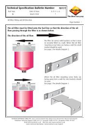
Minimum flow rate<br />
adjustment screw<br />
T O B Y<br />
D V R<br />
+<br />
+<br />
_<br />
_<br />
+<br />
+<br />
_<br />
Maximum flow rate<br />
adjustment screw<br />
Pin operated by <strong>Flexitemp</strong><br />
If the <strong>Flexitemp</strong> arm does not lift<br />
clear of the pin when energized and<br />
the valve control setting is at “6”,<br />
the hexagon pad should be screwed<br />
higher into the operating arm.<br />
6 MM<br />
_<br />
NOTE:- All valves are supplied precalibrated;<br />
if it is necessary<br />
to re-calibrate, all adjustments<br />
to the flow rate screws should<br />
be in increments of no more<br />
than a quarter turn at a time.<br />
Allow at least four minutes for stabilizing<br />
after each adjustment<br />
The pin is located within a tube nut If the <strong>Flexitemp</strong><br />
pushes the pin to give a lower fuel rate than “position<br />
1” the nut should be turned<br />
anticlockwise to provide a higher stop for the <strong>Flexitemp</strong>.<br />
If the minimum flow setting has been adjusted, this<br />
adjustment will be necessary.<br />
© EUROHEAT DISTRIBUTORS (H.B.S) LTD. Nov. 2004 9 Operating <strong>Instructions</strong> Part number IN1051 Edition B