Flexitemp Instructions - Euroheat
Flexitemp Instructions - Euroheat
Flexitemp Instructions - Euroheat

You also want an ePaper? Increase the reach of your titles
YUMPU automatically turns print PDFs into web optimized ePapers that Google loves.
<strong>Euroheat</strong> Distributors<br />
(H.B.S.) Ltd.,<br />
Unit 2, Court Farm<br />
Business Park,<br />
Bishops Frome,<br />
Worcestershire,<br />
WR6 5AY.<br />
<strong>Flexitemp</strong> <strong>Instructions</strong><br />
BM and Toby<br />
Pass this Manual to the User After Installation<br />
© EUROHEAT DISTRIBUTORS (H.B.S) LTD. Nov. 2004 1 Operating <strong>Instructions</strong> Part number IN1051 Edition B
Oil Control<br />
Type<br />
B M<br />
C I<br />
TOBY<br />
Visual Identification<br />
<strong>Flexitemp</strong><br />
Installation of <strong>Flexitemp</strong> and suggested uses.<br />
For System Centre 2 Installation see Stove and Boiler Management Systems Documentation<br />
Suitable <strong>Flexitemp</strong>s for different Oil Control valves<br />
There are 3 types of oil control valves used on the Efel stoves. Use only the <strong>Flexitemp</strong> or System centre listed<br />
below for each type of oil control valve.<br />
<strong>Flexitemp</strong><br />
Part Number<br />
Document<br />
Instruction<br />
Information<br />
Page<br />
© EUROHEAT DISTRIBUTORS (H.B.S) LTD. 2004 2<br />
Operating <strong>Instructions</strong> Part number IN1051 Edition B
The <strong>Flexitemp</strong> unit is an electrically operated device<br />
designed to control the stove’s heat output. It does so<br />
by holding the oil metering valve at its minimum setting<br />
when de-energized, and when energized allows the<br />
valve to deliver oil to the burner at any chosen setting.<br />
It operates by heating a coil around the actuating rod<br />
which then extends its length and causes the operating<br />
Because the <strong>Flexitemp</strong> allows the stove to be<br />
controlled by electrical switching devices, such as<br />
timers or thermostats, it can form the heart of many<br />
Two types of <strong>Flexitemp</strong> are available<br />
A) BM for BM & CI Oil Control Valves<br />
B) Toby for Toby oil Control Valves<br />
Electrical connection for simple mains failure or remote<br />
switching mechanism.<br />
1 2 3 4<br />
L N E<br />
240 Volts a.c<br />
Fused at 3 amps<br />
The <strong>Flexitemp</strong> Oil<br />
Valve Controller<br />
1 2 3 4<br />
N 240V L<br />
A) BM <strong>Flexitemp</strong> Part Number MS9036 Electrical Connection<br />
Electrical connection for remote thermostat control<br />
directly connected to <strong>Flexitemp</strong><br />
© EUROHEAT DISTRIBUTORS (H.B.S) LTD. Nov. 2004 3 Operating <strong>Instructions</strong> Part number IN1051 Edition B<br />
1<br />
C<br />
1 2 3 4<br />
L N E<br />
240 Volts a.c<br />
Fused at 3 amps<br />
2
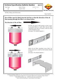
Installing the <strong>Flexitemp</strong> to BM and CI Oil Control<br />
The wiring of all electrical components fi tted to a stove should allow for the stove’s surface and radiated heat,<br />
no electrical wiring should be undertaken by anyone not suitably qualifi ed and conversant with any regulations,<br />
and necessary precautions applicable to the installation of the <strong>Flexitemp</strong> unit. All planned electrical connections<br />
should be installed prior to the attachment of the <strong>Flexitemp</strong> to the Oil Control valve.<br />
The stove must be cold and all electrical and fuel supplies should be isolated when fi tting any components to<br />
the stove.<br />
The three top-plate mounting screws which will be covered by the <strong>Flexitemp</strong> unit should be removed. The<br />
cover of the <strong>Flexitemp</strong> unit should be removed, placed over the valve so that the <strong>Flexitemp</strong> operating arm pad<br />
is concentric with the valve fi ring rate pin and the three holes in the <strong>Flexitemp</strong> body allow the top-plate screws<br />
to be refi tted, passing through, and securing the <strong>Flexitemp</strong> body. Ensure the valve control knob will not foul<br />
against the <strong>Flexitemp</strong> cover when replaced and that the auto/manual lever is set to automatic.<br />
Turn the valve to its minimum “on” position and adjust the <strong>Flexitemp</strong> low position limit screw to cause the<br />
operating arm pad to rest on, but not infl uence the valve fi ring rate pin.<br />
The <strong>Flexitemp</strong> and its control should be subjected to a full mechanical and electrical operation test.<br />
Note:<br />
See <strong>Flexitemp</strong> commissioning instructions to complete installation.<br />
CI Oil Control Valves<br />
remove low setting location<br />
clicker<br />
Valve fi ring rate pin<br />
© EUROHEAT DISTRIBUTORS (H.B.S) LTD. 2004 4<br />
Operating <strong>Instructions</strong> Part number IN1051 Edition B<br />
6<br />
OFF<br />
5<br />
Override<br />
1<br />
3<br />
Automatic<br />
Low position<br />
Limit screw
Commissioning the BM <strong>Flexitemp</strong><br />
Once the installation has been completed the <strong>Flexitemp</strong> requires adjusting to correctly control the minimum<br />
oil flow rate when the <strong>Flexitemp</strong> is de-energized.<br />
The protruding control lever of the <strong>Flexitemp</strong> presses down on the valve firing rate pin. The degree to which<br />
this is pressed determines the flow rate to the burner. To correctly adjust the <strong>Flexitemp</strong> the appliance must be<br />
fully installed and normal stove commissioning completed.<br />
Two checks and possible adjustments need to be completed for correct operation.<br />
A<br />
Remove the coal effect from the appliance.<br />
Light the appliance as described in the operation<br />
instructions.<br />
Once the stove has reached operational temperature<br />
turn the main control knob to the number “1”<br />
position.<br />
The control to the <strong>Flexitemp</strong> must be calling for heat<br />
so that the <strong>Flexitemp</strong> control lever is not touching the<br />
valve firing rate pin.<br />
Observe the flame size.<br />
Remove the electrical power from the <strong>Flexitemp</strong> by<br />
switching off the connecting time clock or other control<br />
system.<br />
The <strong>Flexitemp</strong> control lever should now drop and press<br />
on to the Valve firing rate pin.<br />
The flame size should not change. If the flame reduces<br />
in size the <strong>Flexitemp</strong> control lever is pressing to greatly<br />
on the Valve firing pin.<br />
BM <strong>Flexitemp</strong>, Adjust the low position limit screw<br />
clockwise in small increments until the flame size<br />
returns to the originally observed size.<br />
B<br />
Once section “A” of <strong>Flexitemp</strong> commissioning has<br />
been completed section “B” checks that the <strong>Flexitemp</strong><br />
control lever will reduce the oil flow rate to the number<br />
“1 “ setting and not for example to the number “2” oil<br />
control setting.<br />
With the <strong>Flexitemp</strong> de-energized turn the oil control<br />
knob to the number “4” setting. The flame size should<br />
not change. If The flame size increases the <strong>Flexitemp</strong><br />
oil control lever is not pressing sufficiently on to the<br />
valve firing pin.<br />
BM <strong>Flexitemp</strong>, Turn the low position limit screw<br />
anticlockwise in small increments until the flame<br />
returns to the number “1” setting.<br />
© EUROHEAT DISTRIBUTORS (H.B.S) LTD. Nov. 2004 5 Operating <strong>Instructions</strong> Part number IN1051 Edition B<br />
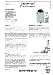
FIG82A<br />
Minimum for low fire<br />
setting<br />
E x c e p t a b l e<br />
Flame Patterns<br />
Valve Firing Rate Pin<br />
Maximum for low<br />
fire setting<br />
Unacceptable Flame Pattern<br />
Caution after adjusting wait 3-4 minutes<br />
for the flame pattern to settle before<br />
continuing commissioning.
B) Toby <strong>Flexitemp</strong> Part Number MS10040<br />
Electrical oil valve control with the <strong>Flexitemp</strong>.<br />
1 2 3 4 5 6<br />
The <strong>Flexitemp</strong> allows the oil valve to be controlled automatically, and can be used to govern the firing rate of a<br />
stove with a boiler as illustrated in the two following drawings. High and low limit thermostats are incorporated<br />
to protect the boiler from condensation by not allowing it to run at too low a temperature and dissipating<br />
excess heat should the control thermostat fail. The high limit and control thermostat should be fitted at the<br />
boiler flow outlet and the low limit thermostat should be fitted to the boiler return inlet. All pipe thermostats<br />
must be fitted using heat conducting paste between the thermostat’s monitoring face and the pipe to ensure<br />
reliable thermal transmission. High temperature cables must be used to wire components in contact with or<br />
in close proximity to the stove. All wiring must be in accordance with whatever regulations may be applicable<br />
at the time of installation.<br />
Schematic electrical diagram for system with gravity D.H.W. and pumped space heating circuit.<br />
L<br />
N<br />
Pump<br />
1<br />
C<br />
90 C<br />
o<br />
2 1<br />
C<br />
2<br />
50 C<br />
o<br />
High Limit Low Limit<br />
Room<br />
Thermostat<br />
1 2 3 4 5 6<br />
<strong>Flexitemp</strong> unit.<br />
Control<br />
Thermostat<br />
Schematic electrical diagram for system with gravity D.H.W. and pumped space heating circuit, where no<br />
room thermostat is fitted.<br />
L<br />
N<br />
Pump<br />
1<br />
C<br />
90 C<br />
o<br />
2 1<br />
C<br />
2<br />
50 C<br />
o<br />
High Limit Low Limit<br />
© EUROHEAT DISTRIBUTORS (H.B.S) LTD. 2004 6<br />
Operating <strong>Instructions</strong> Part number IN1051 Edition B<br />
1<br />
C<br />
2<br />
<strong>Flexitemp</strong> unit.<br />
1<br />
C<br />
2<br />
1 2 3 4 5 6<br />
Control<br />
Thermostat<br />
CH<br />
HW<br />
CH<br />
HW
Schematic electrical diagram for system with<br />
both D.H.W. and space heating circuit being<br />
pumped.<br />
N<br />
Pump<br />
1<br />
C<br />
90 C<br />
o<br />
2 1<br />
C<br />
2<br />
50 C<br />
o<br />
High Limit Low Limit<br />
Room 1 2 3 4 5 6<br />
Thermostat<br />
<strong>Flexitemp</strong> unit.<br />
Schematic electrical diagram for system with no boiler but where it is required to control<br />
stove’s heat output with a room thermostat and a time switch.<br />
N<br />
1 2 3 4 5 6<br />
<strong>Flexitemp</strong> unit.<br />
Control by single Pipe thermostat to maintain control temperature<br />
N<br />
<strong>Flexitemp</strong> unit.<br />
1<br />
C<br />
2<br />
1 2 3 4 5 6<br />
Control<br />
Thermostat<br />
Control<br />
Thermostat<br />
© EUROHEAT DISTRIBUTORS (H.B.S) LTD. Nov. 2004 7 Operating <strong>Instructions</strong> Part number IN1051 Edition B<br />
L<br />
1<br />
C<br />
2<br />
L<br />
HW
Installing the <strong>Flexitemp</strong> to Toby Valve<br />
Isolate all electrical supplies before working on the stove or its controls.<br />
1<br />
Loosen screw “A” and slide off<br />
terminal cover.<br />
3 4<br />
5<br />
C<br />
TO B Y<br />
D V R<br />
The <strong>Flexitemp</strong> is attached to the<br />
Toby valve with two screws. The screw<br />
passing through the <strong>Flexitemp</strong> body “B” is<br />
captive, the other, “C” is taken<br />
from the valve.<br />
TO B Y<br />
D VR<br />
+<br />
+<br />
_<br />
B<br />
A<br />
+<br />
_<br />
Remove these two screws from the<br />
Toby valve, One screw “C” is reused<br />
to mount the <strong>Flexitemp</strong> unit.<br />
Mount <strong>Flexitemp</strong> using the captive screw “B”<br />
and the screw “C” in the hole shown. These should be<br />
screwed into the fixing points on the valve vacated by<br />
the two screws removed.. Note:- The <strong>Flexitemp</strong> is offset Ensure the <strong>Flexitemp</strong> sits flat on the<br />
when mounted.<br />
Valve body. Refit terminal cover.<br />
© EUROHEAT DISTRIBUTORS (H.B.S) LTD. 2004 8<br />
Operating <strong>Instructions</strong> Part number IN1051 Edition B<br />
6<br />
2<br />
T O B Y<br />
D V R<br />
Wire in cable, or cables to <strong>Flexitemp</strong> unit,<br />
ensuring you are wiring to the correct<br />
terminals for your control system, and<br />
and the earth wires are connected to the<br />
earthing terminal of the metal body.<br />
Cables must be secured by the cable<br />
clamp tightened onto the outer sheaths.<br />
TO B Y<br />
D V R<br />
+<br />
_<br />
+<br />
+<br />
_<br />
C
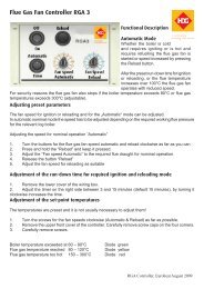
Commissioning and operation of the Toby <strong>Flexitemp</strong><br />
The valve contains and controls a reservoir of oil, maintained at the height marked on the valve body. The<br />
delivery rate of the valve is governed by a slotted barrel at the valve’s exit being raised or lowered within a sleeve<br />
to expose more or less of this slot to the reservoir of oil. The position of the barrel is controlled by a cam, in<br />
the form of an adjustable track, attached to the control knob shaft. When the valve is in the “off “ position the<br />
track causes the barrel to be pushed down within the sleeve so that none of the slot is exposed and so no oil<br />
flows out from the valve. As the control knob turns from the “off” position to position “6” the track rotates over<br />
the barrel allowing the barrel to raise progressively to expose the full length of its slot. The final calibration of<br />
the valve’s flow rate is made by adjustment of the two screws holding the ends of the track, so that the height<br />
of the track and the position of the barrel, when the control knob is at position “1” and “6”, is determined. The<br />
barrel movement necessary to give the flow rates from low to high flow is approximately one mm.<br />
Above the flow regulating barrel is a pin, which protrudes through the valve cover plate, and it is this pin that<br />
the <strong>Flexitemp</strong> arm operates. When the <strong>Flexitemp</strong> unit is not energized the arm pushes down the pin and lowers<br />
the barrel to position ”1”. When energized, the <strong>Flexitemp</strong> arm lifts clear of the pin to allow the barrel to rise to<br />
whatever position is set on the control knob. The <strong>Flexitemp</strong> arm is actuated by heating an expanding metal<br />
rod which causes the arm to lift or lower very slowly, about three minutes. This slow operation allows more<br />
time for the flue draught to stabilize as the stove’s firing rate changes.<br />
Minimum flow rate<br />
adjustment screw<br />
T O B Y<br />
D V R<br />
+<br />
+<br />
_<br />
_<br />
+<br />
+<br />
_<br />
Maximum flow rate<br />
adjustment screw<br />
Pin operated by <strong>Flexitemp</strong><br />
If the <strong>Flexitemp</strong> arm does not lift<br />
clear of the pin when energized and<br />
the valve control setting is at “6”,<br />
the hexagon pad should be screwed<br />
higher into the operating arm.<br />
6 MM<br />
_<br />
NOTE:- All valves are supplied precalibrated;<br />
if it is necessary<br />
to re-calibrate, all adjustments<br />
to the flow rate screws should<br />
be in increments of no more<br />
than a quarter turn at a time.<br />
Allow at least four minutes for stabilizing<br />
after each adjustment<br />
The pin is located within a tube nut If the <strong>Flexitemp</strong><br />
pushes the pin to give a lower fuel rate than “position<br />
1” the nut should be turned<br />
anticlockwise to provide a higher stop for the <strong>Flexitemp</strong>.<br />
If the minimum flow setting has been adjusted, this<br />
adjustment will be necessary.<br />
© EUROHEAT DISTRIBUTORS (H.B.S) LTD. Nov. 2004 9 Operating <strong>Instructions</strong> Part number IN1051 Edition B