Rika Visio Instructions - Euroheat
Rika Visio Instructions - Euroheat
Rika Visio Instructions - Euroheat

You also want an ePaper? Increase the reach of your titles
YUMPU automatically turns print PDFs into web optimized ePapers that Google loves.
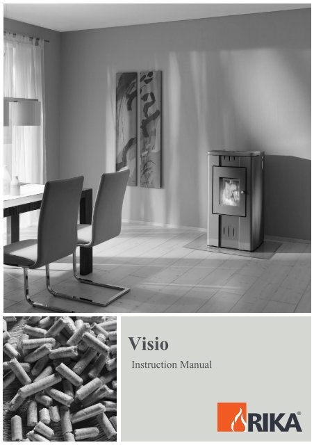
<strong>Visio</strong><br />
Instruction Manual
CONTENTS<br />
Technical specification and spare parts overview 33<br />
1. IMPORTANT INFORMATION 34<br />
2. WHAT ARE PELLETS? 34<br />
Quality characteristics, storage 34<br />
3. TECHNOLOGY 35<br />
4. AUTOMATIC SAFETY FUNCTIONS<br />
Power failure 35<br />
Overheating 35<br />
Low temperature switch off 35<br />
Electrical excess current switch off 35<br />
5. INSTALLING THE STOVE<br />
General information 36<br />
Making the chimney connection 36<br />
Method 36<br />
Floor protection 36<br />
Safety distances 36<br />
Electrical connection 37<br />
Combustion air 37<br />
Feed of external combustion air 37<br />
6. FITTING THE PANELLING, OPTIONS<br />
General 38<br />
Fitting the aluminium or ceramic side panels 38<br />
Fitting convection fan (optional) 38<br />
7. OPERATION<br />
Basic information 39<br />
Control and internal control unit – function 39<br />
Internal control unit 39<br />
8. UNIT COMMISSION ING/CONTROL<br />
PROGRAMMING/CONTROL OPTIONS<br />
General 40<br />
First commissioning/program settings 40<br />
Main menu operating areas 43<br />
Shut down unit 44<br />
Shut down from “Manual operation (ON)” 44<br />
Shut down unit from automatic operation 45<br />
Automatic stop controlled by heating time 45<br />
Automatic stop, manual 45<br />
Shut down by operating mode in Standby 45<br />
Pellet control (optional) room temperature sensor 45<br />
Tele-Control (telephone control optional) 45<br />
9. ELECTRICAL IGNITION<br />
Pre-heating without electrical ignition 46<br />
Some field values 46<br />
Fuel feed 46
10. CLEANING AND MAINTENANCE<br />
Basic Information 48<br />
Cleaning the fire tray 47<br />
Cleaning the grate door glass 47<br />
Cleaning the flue gas channels 47<br />
Cleaning exhaust gas collector 48<br />
Cleaning exhaust gas fan housing 49<br />
Cleaning pellet container 49<br />
Inspecting door seal 49<br />
Checking chimney connection 49<br />
Cleaning air sensor 49<br />
11. FAULTS – CAUSES - SOLUTIONS<br />
Error messages control 51<br />
12. APPENDIX<br />
Menu navigation for programming of internal control 53<br />
Keyword, abbreviation index 54<br />
EC-Declaration of conformity 55<br />
Commission ing instructions and certificate 56<br />
13 GUARANTEE<br />
We guarantee 57<br />
Guarantee card 107<br />
Subject to technical and visual changes; setting and printing errors excepted.<br />
EXPLANATION OF SYMBOLS<br />
Important information<br />
Practical advice<br />
Use the plan
E N G L I S H<br />
TECHNICAL SPECIFICATION<br />
(Fig. 1)<br />
TECHNICAL DATA<br />
Height mm] 1031<br />
Width [mm] 530<br />
Depth of the corpus [mm] 576<br />
Weight without casing [daN] 135<br />
Weight with ceramic casing [daN] 145<br />
Smoke tube pipe diameter [mm] 100<br />
Heating performance range [kW] 2,4 - 8<br />
Room heating capacity (m3)<br />
dependent on house insulation<br />
Efficiency [%] 94,5<br />
CO2 content [%] 10,7<br />
CO emission re. 13% O [mg/Nm3] 74<br />
Dust emissions [mg/Nm3] 22<br />
Exhaust air mass flow [g/s] 5,5<br />
Exhaust air temperature [°C] 100,3<br />
Chimney draft requirement [Pa] 0<br />
The owner of the small heating system or the<br />
authorised person for the small heating system must<br />
keep the technical documentation in a safe place<br />
and present it to the local authority or the chimney<br />
sweep if required.<br />
1. PACKAGING<br />
[m3] 50-210<br />
Fuel consumption [kg/h] 0,6-1,9<br />
Pellet container capacity [kg] 32<br />
Power supply [V]; [Hz] 230; 50<br />
Average electrical power<br />
consumption<br />
[W] ca. 100<br />
Fuse [A] 1,6 T<br />
Your first impression is important to us!<br />
The packaging for your new stove provides excellent<br />
protection against damage. However damage to the<br />
stove and accessories can occur during transport.<br />
SPARE PARTS - OVE RVIEW<br />
(Fig. 3 - Fig. 7)<br />
DESCRIPTION<br />
01 Fire door<br />
02 Fire door seal<br />
03 Fire door glass<br />
04 Upper temperature limiter<br />
05 Ignition element<br />
06 Conveyorscrew complete<br />
07 Centring plate<br />
08 Motor plate<br />
09 Hexagonal bolt<br />
10 Conveyor screw drive motor<br />
11 Air sensor<br />
20 Internal control unit<br />
21 Main fuse<br />
22 Main board<br />
23 Remote fixed network board (optional)<br />
30 Wing nut<br />
31 Flue gas shaft cleaning lid<br />
32 Intermediate bottom<br />
33 Top/bottom cleaning lid<br />
34 Exhaust gas fan housing<br />
35 Exhaust gas fan motor<br />
36 Hexagonal screws<br />
37 Low temperature switch<br />
38 Smoke tube adapter 100 mm<br />
39 Fire door hinge<br />
40 Container lid (with rating plate, warning sign)<br />
41 Rear wall<br />
42 Side cladding rear right complete<br />
43 Rear wall cover<br />
44 Mains cable with earthed plug<br />
45 Right panel<br />
46 Front cladding bottom<br />
47 Front cladding top<br />
48 Left panel<br />
49 Rear left panel complete<br />
50 Lamination cover complete<br />
Therefore please check that your stove is undamaged<br />
and that all parts are there on receipt! Report any<br />
defects to your stove dealer immediately!<br />
When unpacking make absolutely sure that the stone<br />
panelling is not damaged. It is very easy to scratch the<br />
material. Ceramic panelling is not covered under the<br />
guarantee.<br />
- The packaging for your new stove generally has no<br />
effect on the environment. The box and the film (PE)<br />
can be safely taken to the local council waste<br />
disposal depot for recycling.
1. IMPORTANT INFORMATION<br />
GENERAL WARNING AND SAFETY<br />
INSTRUCTIONS<br />
The general introductory warning information must<br />
be followed.<br />
● Read the whole of the manual thoroughly before<br />
commissioning the stove.<br />
● Only approved transport aids with adequate load<br />
bearing capacity must be used for transporting your<br />
stove.<br />
● Your stove is not suitable for use as a ladder or<br />
scaffold.<br />
● Thermal energy is produced by burning fuel; this<br />
leads to the surface of the stove, the doors, the door<br />
and operating handles, the door glasses, the flue<br />
pipes and possibly the front wall of the stove<br />
becoming very hot. Avoid touching these parts<br />
without wearing the relevant protective clothing or<br />
using the relevant means (cold hand).<br />
2. WHAT ARE PELLETS ?<br />
Pellets are made from wooden waste, from sawmills<br />
and planing workshops, as well as from residue from<br />
forestry operations. These “starting products” are<br />
crushed, dried, and pressed into Pellet “Fuel”<br />
without any bonding agent.<br />
SPECIFICATIONS FOR HIGH<br />
QUALITY PELLETS<br />
Calorific Value: 5.3 kWh/kg<br />
Density: 700 kg/m3<br />
Water Content: Max. 8% of the weight<br />
Ash proportion: Max. 1% of the weight<br />
Diameter: 5 - 6.5mm<br />
Length: Max. 30mm<br />
Contents: 100% wood untreated and without<br />
any bonding agents added (bark<br />
proportion max. 5%)<br />
Packaging: In sacks, made of environmentally<br />
neutral or biologically degradable<br />
plastic, or from paper (2-3 layers /<br />
similar to cement packaging)<br />
● Make children aware of the danger and keep<br />
them away from the stove when in use.<br />
● Placing non heat resistant objects on the stove or<br />
nearby is prohibited.<br />
● Do not lay washing on the stove to dry.<br />
● Stands for drying items of clothing or suchlike<br />
must be set up at an adequate distance from the<br />
stove – fire hazard!<br />
● Working with easily combustible and explosive<br />
materials in the same or adjoining room to the stove<br />
is prohibited when the stove is on.<br />
● ATTENTION!!<br />
In cause of safety reason please do not open the<br />
combustion chamber door during operation!<br />
● CAUTION when filling the storage container.<br />
The opening of the pellet container is sufficient to<br />
ensure problem-free filling. Ensure that no pellets<br />
fall on the convection ribs and the hot stove body.<br />
This can otherwise lead to heavy smoke formation.<br />
Please ask your pellet stove dealer for tested fuel and<br />
a list of monitored fuel manufacturers. Using poor<br />
quality or prohibited pellet fuel will have a negative<br />
effect on the function of your pellet stove and can also<br />
lead to the warranty becoming null and void, as well as<br />
the product liability connected with this. Observe<br />
waste incineration legislation.<br />
Burn only pellets that have been tested.<br />
PELLET STORAGE<br />
In order to guarantee problem free burning of the<br />
wooden pellets, it is necessary to store the fuel as<br />
dry as possible and free from impurities.<br />
Pellets should not be kept in sacks outdoors or<br />
stored in a manner where they are exposed to the<br />
environment. This can lead to blockages in the<br />
screw conveyor - "screw stoppers" are excluded<br />
from the warranty.<br />
E N G L I S H
E N G L I S H<br />
3. TECHNOLOGY<br />
Your new pellet stove is technologically advanced<br />
as a result of years of tests in the laboratory and in<br />
practice. The practical advantages of your pellet<br />
stove are convincing:<br />
OPERATING COMFORT –<br />
OPERATIONAL RELIABILITY<br />
The electronic monitoring device together with a<br />
patented “air sensor” controls and regulates the<br />
interplay of flue gas fan, conveyor auger, convection<br />
fan (optional) and temperature.<br />
This monitoring system guarantees an optimum<br />
combustion and operating mode.<br />
4. AUTOMATIC SAFETY FUNCTION<br />
POWER FAILURE<br />
After a short power failure the operating functions<br />
that were set before the power failure are continued.<br />
ON mode (manual operation). The control switches<br />
to the ST (Start Phase) and the unit then re-runs in<br />
ON operation. TM mode (automatic operation). The<br />
control switches to the ST (Start Phase) and the unit<br />
then re-runs in TM operation. SB mode (operational<br />
readiness, standby operation). After two seconds<br />
the control re-runs in the SB operation.<br />
On power failure a small amount of smoke may be<br />
emitted. This does not last for more than three to<br />
five minutes and does not represent a safety risks.<br />
OVERHEATING<br />
A temperature safety switch (STL) switches the<br />
stove off automatically if it overheats. After the stove<br />
has cooled down it returns to the regulating<br />
program.<br />
Your operating outlay is reduced to the most<br />
necessary - this prevents operating faults whilst<br />
working in an optimum fashion at the same time.<br />
HIGHEST EFFICIENCY - LOWEST<br />
EMISSIONS<br />
A very large heat exchanger surface togetherwith<br />
optimum combustion air control leads to very good<br />
fuel usage. Finely metered pellet feed in an<br />
optimised burner pot made from high quality grey<br />
cast iron effects almost perfect combustion with very<br />
good exhaust gas values - and this is guaranteed in<br />
every operating phase.<br />
Whether the heating operation is continued or not<br />
depends on the remaining embers in the fire pan. If<br />
re-ignition does not occur when the fuel supply<br />
recommences, then the out of operation program<br />
(cleaning , lag phase) is carried out. According to<br />
the pre-set mode the stove must be re-started.<br />
CAUTION: If overheating has occurred then<br />
maintenance or cleaning work must be carried out.<br />
LOW TEMPERATURE SWITCH OFF<br />
If the stove cools down below a minimum<br />
temperature, then the stove will switch off. This<br />
switch off can also occur if pre-heating is too slow.<br />
ELECTRIC EXCESS-CURRENT<br />
SHUT OFF<br />
The device is protected against excess current by a<br />
main fuse (on the rear of the device), (see<br />
“Technical Specification”).
5. INSTALLING THE STOVE<br />
GENERAL INFORMATION<br />
The stove must be connected to a chimney that is<br />
approved for solid fuels. The chimney must have a<br />
diameter of at least 120 mm.<br />
The flue system is based on negative pressure in<br />
the combustion chamber and a slight overpressure<br />
on the flue gas outlet. It is therefore important that<br />
the flue gas connection is fitted correctly and is<br />
airtight.<br />
Only use heat resistant sealing materials, as well as<br />
the relevant sealing bands, heat resistant silicon and<br />
mineral wool.<br />
Only authorised technical personnel must carry out<br />
assembly work.<br />
In addition you must ensure that the flue tube does<br />
not project into the free cross section of the<br />
chimney.<br />
NOTE: Please follow the regionally valid building<br />
regulations. Contact your master chimney sweep for<br />
information on this.<br />
Ensure that outlet routes to the chimney are not too<br />
long.<br />
Avoid too many changes of direction for the flue gas<br />
flow to the chimney. (e.g. too many corners and<br />
bends).<br />
Where you cannot connect directly to the<br />
chimney, if possible use a connection piece with<br />
cleaning opening.<br />
For optimum efficiency please use the type of<br />
connector we recommend.<br />
MAKING THE CHIMNEY<br />
CONNECTION<br />
(Fig. 1)<br />
Method<br />
1. Measure and draw the chimney connection<br />
(taking any floor plate thickness into<br />
consideration). (Fig. 1)<br />
2. Chisel out (drill) the hole in the wall<br />
3. Brick in the wall lining<br />
4. Connect stove with the flue tube to the<br />
chimney.<br />
FLOOR PROTECTION<br />
For flammable floor surfaces (wood, carpet, etc.) a<br />
glass, steel plate or ceramic underlay is required.<br />
SAFETY DISTANCES<br />
(Fig. 2)<br />
(Measured from the outside of the<br />
stove)<br />
From non-combustible objects<br />
a > 400 mm b > 100 mm c > 100 mm<br />
From combustible objects and to load-bearing walls in<br />
reinforced concrete<br />
a > 800 mm b > 200 mm c > 200 mm<br />
E N G L I S H
E N G L I S H<br />
ELECTRICAL CONNECTION<br />
The stove is supplied with an approx. 2.5 m long<br />
connecting cable with a plug. The cable must be<br />
connected to a 230 V, 50 Hz electrical supply. The<br />
average electric power consumption is approx 100<br />
watts during heating. During the automatic ignition<br />
process (duration 10 minutes) approx. 350 watts.<br />
The connection cable must be laid so that any<br />
contact with hot or sharpedged external surfaces on<br />
the stove is avoided.<br />
COMBUSTION AIR<br />
Each combustion procedure requires oxygen or air.<br />
As a rule this combustion air is removed from the<br />
living area for individual stoves The air taken from<br />
the living area must be reintroduced. In modern<br />
houses, very tight fitting windows and doors mean<br />
that too little air flows back. This situation becomes<br />
problematic due to additional ventilation in the<br />
house (e.g. in the kitchen or WC).<br />
The suctioning in of combustion air is performed via<br />
the flue gas blower. The resulting combustion air<br />
and suctioning noises are normal operational noises<br />
that may occur at varying volumes depending on the<br />
chimney draught, output level or a dirty combustion<br />
trough – NOT A CAUSE FOR COMPLAINT!<br />
Minimum diameter<br />
5 cm / 2 inch<br />
Wall<br />
Feed of external combustion air<br />
● Steel, HT or flexible aluminium pipes must be<br />
used.<br />
● Minimum diameter 5 cm/2 inches.<br />
● For longer connection runs the diameter must be<br />
increased to approx. 10 cm after approx. 1 m.<br />
● The pipe should not be longer than approx. 4m<br />
in total to guarantee adequate air feed and not<br />
have too many bends.<br />
● Should the line lead into the open air, it must<br />
end with a vertical 90° downward elbow or with a<br />
wind guard.<br />
Should one or more of these conditions NOT be<br />
applicable then usually poor combustion will occur<br />
in the stove, as well as air underpressure in the<br />
apartment.<br />
We recommend that a ventilating grille be fitted in a<br />
window near the stove for permanent ventilation.<br />
Further it is possible to extract the combustion air<br />
directly from outside or from another room that is<br />
well ventilated (e.g. the cellar).<br />
Please observe:<br />
Your pellet stove works independent of the room air.<br />
Negative pressures in the set-up room are not<br />
permissible. Therefore the use of a safety device<br />
(e.g. differential pressure controller) in combination<br />
with room air facilities (e.g. ventilation system,<br />
exhaust extraction etc.) is stipulated.
6. ASSEMBLY, PANELLING, OPTIONS<br />
GENERAL<br />
CAUTION: Only work on the stove when the mains<br />
plug has been removed from the socket.<br />
During assembly do not drop any items (screws) etc.<br />
into the fuel container - they can block the conveyor<br />
auger and damage the stove.<br />
Your stove must be switched off and have cooled<br />
down before work is carried out.<br />
FITTING THE STEEL OR CERAMIC<br />
PANELS<br />
(Fig. 6)<br />
1. Remove the cover insert (Fig 7, 63) from the<br />
cast cover and remove the two hexagonal<br />
screws (Fig 7, 66). Now remove the cast cover<br />
from the pellet stove.<br />
2. From above push the side panels (Fig 6, 44 and<br />
49) into the holders (upper and lower) provided<br />
on the stove.<br />
3. Check the position of the side panel in the<br />
lower area of the cast base. If re-positioning is<br />
necessary this can be done by appropriate<br />
adjustment of the hexagonal screw (Fig 6, part<br />
48)<br />
4. The side panel is then additionally secured with<br />
the hexagonal screw (Fig 6, part 50).<br />
5. The procedure for both sides is the same.<br />
6. Now position the cast cover on the pellet stove<br />
and secure it with the two Allen screws as per<br />
step 1. The cover insert can now be re-fitted.<br />
ASSEMBLY OF CONVECTION FAN<br />
(OPTIONAL)<br />
(Fig. 6)<br />
Dismantle the rear side panels (Fig 6, 45.51) left<br />
and right by removing the hexagonal screws in the<br />
pellet container and at the back in the rear panel. Be<br />
careful of the cable to the internal operating unit.<br />
Fig 1 Nut<br />
Attach the convection fan by screwing the two nuts<br />
supplied to the two bolts incorporated into the<br />
combustion chamber rear wall (Fig 1). Place a<br />
serrated washer under one of the nuts.<br />
Fig 2 Nut Convection fan connector<br />
Lay the mains cable in the holders on the control<br />
PCB housing and insert the two-pin plug into<br />
position III. Re-fit the rear side panels on the left and<br />
right side.<br />
CAUTION! Installation of the convection fan must be<br />
carried out by an authorised dealer.<br />
E N G L I S H
E N G L I S H<br />
7. OPERATION<br />
BASIC INFORMATION<br />
The stove must only be started when fully fitted.<br />
Your pellet stove is exclusively for burning pellets<br />
made from wood of a controlled quality. Non-pelletised<br />
solid fuels (straw, maize, chopped matter etc.) are not<br />
permitted. Failure to adhere to these guidelines will<br />
make all guarantee and warranty claims null and void<br />
and could have a negative effect on the safety of your<br />
stove.<br />
When operated correctly your pellet stove cannot<br />
overheat. Improper operation can however shorten the<br />
life expectancy of the electric stove components (fan,<br />
motors and electric control) and is not permitted.<br />
CONTROL AND INTERNAL<br />
CONTROL UNIT - FUNCTION<br />
(Fig. 4, Part 20)<br />
Your pellet stove is fitted with a modern<br />
programmable microprocessor control. The user can<br />
preset the individual stove functions via the internal<br />
control unit (keypad with operating display) fitted at<br />
the top of the right hand stove panel.<br />
The control (main board) and the control board may<br />
only be altered by trained specialist dealers or the<br />
service department. Improper handling of these<br />
parts leads to the guarantee and warranty becoming<br />
null and void.<br />
INTERNAL CONTROL UNIT<br />
All settings and functions can be regulated<br />
via this unit.<br />
Fig 1. Internal operating unit, key layout<br />
DISPLAY PANEL:<br />
Display of operating state in illuminated text<br />
MENU:<br />
Navigation in and to the various sub-menu levels<br />
ENTER:<br />
Navigation in the main menus (SB, ON, TM) and<br />
confirmation of use inputs<br />
MINUS/PLUS:<br />
Decrease and increase of user values<br />
ON/OFF:<br />
Switching unit on and off<br />
For a graphical representation of the menu<br />
navigation of the program levels see Appendix,<br />
page 29
8. DEVICE COMMISSIONING / CONTROL PROGR AMMING / CONTROLOTIONS<br />
GENERAL<br />
● Check that the pellet container is full and the<br />
combustion chamber is clean and contamination<br />
free.<br />
CAUTION: During the ignition process the grate door<br />
must be closed. The electronic ignition does not work<br />
if the grate door is open.<br />
When the pellet container of the stove is filled for the<br />
first time, no pellets are conveyed to the fire tray for<br />
about 10 minutes. You can put a handful of pellets in<br />
the fire pan to avoid a new start process.<br />
FIRST COMMISSIONING/<br />
PROGRAMME SETTINGS<br />
After filling the supply container and connecting the<br />
stove to the mains electrical supply, press the<br />
ON/OFF key on the internal operating unit and SB<br />
(Standby) is displayed.<br />
“SB” = standby operation<br />
Now program your control for your individual<br />
requirements as follows: (See page 29 for menu<br />
navigation). Two heating intervals can be<br />
programmed for each weekday. No heating times<br />
are programmed in the factory. Press “MENU” on<br />
the operating unit and the display shows the<br />
following:<br />
“MO” = Monday<br />
Now press “ENTER” and the display shows:<br />
“S1” = start first heating time, 6 the<br />
number is the time in hours (0 to 23<br />
hours) e.g. see window 6 Hour.<br />
By pressing the “+” or “-” keys the heating time can<br />
be changed in hourly steps as required. The desired<br />
value is confirmed with “ENTER” and is then saved.<br />
The display shows<br />
“E1” = end of first heating time,<br />
By pressing the “+” or “-” keys the heating time can<br />
be changed in hourly steps as required. The desired<br />
value is confirmed with “ENTER” and is then saved.<br />
The display shows<br />
“S2” = start of second heating<br />
time,<br />
After entering the second heating time and<br />
confirming with “ENTER” the display shows<br />
“E2” = end of second heating time,<br />
After entering the switch off point of the second<br />
heating time and confirming with “ENTER” the new<br />
valued is saved and the display now shows:<br />
E N G L I S H
E N G L I S H<br />
On selecting the “MENU” key the display shows the<br />
following weekday:<br />
“TU” = Tuesday,<br />
Press the “ENTER” key to return to the starting point<br />
of the first heating time for Tuesday.<br />
Proceed to enter the rest of the heating times for the<br />
weekdays (Wednesday “WE”, Thursday “TH”, Friday<br />
“FR”, Saturday “SA”, Sunday “SU” as described<br />
above.<br />
After acknowledgement with “ENTER” of the E2<br />
value of Sunday (SU) and selection of “MENU” the<br />
display shows:<br />
“PS” (Power Start) = heating<br />
output during the programmed<br />
heating times (S1-E2, S2-E2).<br />
The number corresponds to the heating output in<br />
percent (0% equals minimum heating output, 100%<br />
equals maximum heating output).<br />
By pressing the “+” or “-” keys you can change the<br />
value of the heating output in 5% steps as required.<br />
The value is confirmed with “ENTER” and the<br />
display shows<br />
“PE” (Power End) = heating<br />
output between the programmed<br />
heating times (E1-S2).<br />
“OFF” indicates that the stove is switched off<br />
between the programmed heating times.<br />
The value “OFF” is achieved by pressing the “-” key<br />
until “OFF” is displayed.<br />
If you want to maintain a specific heating output (low<br />
operation) between the programmed heating times<br />
you can set the required value by pressing the “+” or<br />
“-” keys.<br />
The number equals the heating<br />
output in percent (e.g. see window<br />
5%).<br />
Press the “ENTER” key to save the PE value, the<br />
display shows:<br />
To improve combustion quality, automatic<br />
cleaning of the fire pan is programmed into the<br />
control process<br />
“CL” = Clean<br />
the number indicates the time<br />
interval in minutes (e.g. see<br />
window 60 Minutes).<br />
By pressing the “+” or “-” keys you can determine<br />
the desired time interval in 5 minute steps (The<br />
cleaning interval can be extended to 300 minutes,<br />
however we recommend a cleaning cycle of 60<br />
minutes). Confirm with “ENTER” and the display<br />
shows:<br />
This is the current software version<br />
of the control and is used for<br />
customer service reasons (display<br />
only).<br />
Now use “MENU” to access the internal clock and<br />
the following display appears:<br />
“H” = Hour the number indicates<br />
the hour (value range 0 to 23).
By pressing the “+” or “-” keys the current hour of<br />
the internal clock can be set. The desired value is<br />
confirmed with “ENTER” and is then saved. The<br />
display shows<br />
“M” = Minutes, the number<br />
indicates the minutes (value range<br />
0 to 59).<br />
Set the minutes of the system clock to the correct<br />
value by pressing the “+” or “-” keys and confirm<br />
with “ENTER”. The value is then saved and the<br />
display shows:<br />
“D” = Day, the number indicates<br />
the weekday, e.g. see window 3 =<br />
Wednesday.<br />
Set the current weekday (1 = Monday, 2 = Tuesday,<br />
3 = Wednesday, 4 = Thursday, 5 = Friday, 6 =<br />
Saturday, 7 = Sunday) by pressing the “+” or “-”<br />
keys and confirm the new value by pressing<br />
“ENTER”. The value is then saved and on pressing<br />
“MENU” the display shows:<br />
a) if the optional Tele-control is installed<br />
“RI” = Rings<br />
The number of ring tones can be<br />
set from 1 to 10.<br />
By pressing the “+” or “-” keys the number of rings<br />
can be changed. Press “ENTER” to confirm and the<br />
value is then saved and the display shows:<br />
“PN1” = PIN 1<br />
(Personal Identification Number).<br />
The number 0 (see window) represents the first digit<br />
of the PIN code (0 - 9 possible):<br />
Select the desired value by pressing the “+” or “-”<br />
keys and confirm with “ENTER”. The display then<br />
shows:<br />
“PN2” = PIN 2<br />
The number 8 (see window)<br />
represents the second digit of the<br />
PIN code:<br />
Press the “+” or “-” keys to select the required value<br />
and confirm with “ENTER”, the display then shows:<br />
“PN3” = PIN 3<br />
The number 1 (see window)<br />
represents the third digit of the PIN<br />
code:<br />
Press the “+” or “-” keys to select the<br />
required value and confirm with “ENTER”,<br />
the display then shows:<br />
“PN4” = PIN 4<br />
The number 5 (see window)<br />
represents the fourth digit of the<br />
PIN code:<br />
Press the “+” or “-” keys to select the required value<br />
and confirm with “ENTER”. Then select “MENU” and<br />
you return to the main menu and the display shows:<br />
b) if the optional Tele-control is installed<br />
“SB” = Standby<br />
Now the stove has been programmed according to<br />
your individual requirements you can set it to<br />
manual mode (ON mode) by a single press on the<br />
“ENTER” key or to automatic mode (TM mode) by<br />
double pressing the “ENTER” key<br />
E N G L I S H
E N G L I S H<br />
Ensure that when the stove is in ON mode the heating<br />
operation starts after 10 seconds. In automatic mode<br />
(TM) the heating process starts in accordance with the<br />
programmed heating times.<br />
MAIN MENU – OPERATING<br />
RANGES<br />
According to your requirements you can choose one<br />
of the following three operating types:<br />
● Standby mode<br />
● Manual operation<br />
● Automatic operation<br />
“SB” = Standby Stove is switched<br />
off but remains active for control by<br />
Tele-Control (mobile).<br />
“ON” = Manual operation The<br />
number equals the heating output<br />
in percent (0% is minimum output<br />
and 100% is maximum heating<br />
output).<br />
“TM” = Automatic operation(Time<br />
mode) The number equals the<br />
heating output in percent (0% is<br />
minimum output and 100% is<br />
maximum heating output.<br />
You can switch between the various operating types<br />
by pressing “ENTER”<br />
Start manual operation.<br />
The following flashing indicators appear alternately<br />
on the display<br />
“ST” indicates start<br />
The number below indicates the remaining time for<br />
the start process in minutes.<br />
On completion of the start phase the following<br />
appears continuously on the display<br />
“ON” = Manual operation<br />
If you want to change the current heating output<br />
then you can set the required heating output in 5%<br />
steps (from 0 to 100) by pressing the “+” or “-” keys.
Start automatic operation (TM mode)<br />
When TM is selected on the display and the<br />
programmed heating time begins the control starts<br />
the heating operation.<br />
The following flashing indications appear alternately<br />
on the display:<br />
“TM” indicates automatic operation.<br />
On completion of the start phase the following<br />
appears continuously on the display<br />
Generally the pre-programmed heating output (PS,<br />
PE) is adopted. If however youwant to change the<br />
current value, then this can be done by pressing the<br />
“+” or “-” keys in 5% steps. The changed value<br />
appears on the display. The program adopts the<br />
new value for the control until the completion of the<br />
current heating window. On starting the following<br />
heating time the programmed value is re-used. A<br />
permanent change of heating output can only be<br />
achieved by programming PS and PE.<br />
Note:<br />
The pre-heating program runs automatically and can<br />
be stopped by changing (“ENTER” key) the operating<br />
state to “SB”. In this case the out of operation mode<br />
(alternating indication “Ex”, see below) runs through<br />
to the end. If the stove is disconnected from the mains<br />
supply (i.e. power cut) during the start phase and then<br />
re-connected to the mains supply, the start phases<br />
starts from the beginning again.<br />
PLACE STOVE OUT OF OPERATION<br />
Switching off from “Manual operation” (ON)<br />
If the “ON/OFF” key is pressed during operation<br />
then the switch off program is activated. The<br />
following alternating flashing indictors appear on the<br />
display:<br />
“Ex” Exit phase 1<br />
The number below is the remaining time in seconds<br />
for this phase.<br />
On completion of Exit phase 1 the display shows<br />
(flashing):<br />
“CL” Cleaning phase<br />
The number below is the remaining time in seconds<br />
for this phase.<br />
On completion of Exit phase 1 the display shows<br />
(flashing):<br />
“Ex” Exit phase 2<br />
The number below is the remaining time in seconds<br />
for this phase.<br />
Note:<br />
The full switching off process lasts for about 8<br />
minutes and cannot be interrupted by the user. On<br />
confirmation of “ON/OFF” the switch off program is<br />
initialised.<br />
E N G L I S H
E N G L I S H<br />
On completion of the switch off program the display<br />
goes off. When the “ON/OFF key is pressed a restart<br />
follows.<br />
SWITCHING OFF STOVE<br />
AUTOMATIC OPERATION<br />
Heating time controlled automatic stop<br />
If during automatic operation the “PE” output is<br />
switched to OFF, then the stove will be switched off<br />
at the end of a heating time as per the abovedescribed<br />
functions. The difference to manual<br />
switch off is that TM is displayed instead of ON.<br />
On completion of the switch off process the<br />
following is displayed:<br />
A pre-programmed heating time re-sets the stove<br />
automatically in operation andthe user can manually<br />
change to the ON mode (e.g. if currently a heating<br />
requirement outside the programmed heating times<br />
is required).<br />
Manual automatic stop<br />
“TM” = Automatic operation (Time<br />
mode) OFF switches off heating<br />
operation.<br />
If during automatic operation the “ON/OFF” key is<br />
pressed the stove goes immediately into switch off<br />
operation. The same indication as described<br />
previously is displayed. On completion of the exit<br />
program the display switches off and the stove can<br />
be re-switched to automatic mode by pressing the<br />
“ON/OFF” key.<br />
SWITCHING OFF BY CHANGING<br />
OPERATINGMODE IN STANDBY<br />
If you change to the Standby mode by pressing the<br />
“ENTER” key in “Manual operation” and in automatic<br />
operation, then switching off as described in the<br />
processabove will be carried out. On completion of<br />
the switching off program the following display<br />
appears:<br />
“SB” = Standby<br />
To re-start the stove a corresponding mode must be<br />
selected or the stove must be started with the<br />
optional Tele-Control (telephone start).<br />
PELLET CONTROL (OPTIONAL)<br />
ROOM TEMPERATURE SENSOR<br />
Using the external operating unit your pellet stove<br />
functionality can be extended by the room<br />
temperature control. This means that the room<br />
temperature is measured by a sensor in the external<br />
operating unit. The function is not part of the<br />
standard delivery and can be retro-fitted if desired.<br />
The corresponding extended functions of the stove<br />
and the programming of the system values are<br />
contained in the retro-fitting instructions.<br />
TELE_CONTROL (TELEPHONE<br />
CONTROL OPTIONAL)<br />
The function is not part of the standard delivery and<br />
can be retro-fitted if desired. The corresponding<br />
extended functions of the stove and the<br />
programming of the system values are contained in<br />
the retro-fitting instructions.
9. ELECTRIC IGNITION<br />
The pellet furnace is fitted with an electric ignition.<br />
This starts to function together with the stove start<br />
program.<br />
Ignition duty cycle: Approx. 12 min.<br />
PRE-HEATING WITHOUT<br />
ELECTRIC IGNITION<br />
● CAUTION: APPLIES ONLY TO STOVES WITHOUT<br />
ELECTRICAL IGNITION<br />
● If your stove is fitted with electric ignition and this<br />
is faulty - please request a service or repair visit!<br />
If your pellet stove is not fitted with electric ignition<br />
proceed as follows:<br />
1. Check that the pellet container is full and the<br />
combustion chamber is clean and free from<br />
impurities. Place approved firelighters in the fire<br />
pan and lay a small handful of pellets on top.<br />
CAUTION: Do not use flammable liquids to<br />
preheat the stove!<br />
2. Light the firelighters in the fire pan using a<br />
match and close the stove doors carefully. Press the<br />
“ON/OFF” button. This setting starts the start<br />
procedure.<br />
SOME FIELD VALUES<br />
Pellet consumption depends on the size of the pellets.<br />
The larger the pellets the slower the feed and vice<br />
versa.<br />
30 kg of pellets should be sufficient for 16 hours of<br />
operation at a setting of “100%”, and about 58 hours<br />
at a setting of “0%” (there may be variations caused<br />
by differences in pellet fuel).<br />
If you have any questions please contact your<br />
authorised pellet stove dealer<br />
FUEL FEED<br />
CAUTION when filling the stove with pellets! Do not<br />
touch the hot stove with the pellet sack. Remove any<br />
pellets that have not been put in the storage container<br />
immediately (Smoke formation)!<br />
To prevent the fire from going out due to lack of fuel,<br />
we recommend that an adequate pellet level is kept<br />
in the storage container. A 15 kg sack of pellets can<br />
be loaded into your pellet stove as soon as the<br />
pellet container is less than half full. Check the filling<br />
level often. The container lid should however always<br />
be kept closed unless the container is being filled.<br />
Pellet container capacity (see technical<br />
specification).<br />
E N G L I S H
E N G L I S H<br />
10. CLEANING AND MAINTENANCE<br />
BASIC INFORMATION<br />
Your stove must be switched off and have cooled<br />
down before carrying out any maintenance activities.<br />
CAUTION: Only carry out maintenance when the mains<br />
plug of the stove has been removed from the socket.<br />
The frequency with which your stove must be<br />
cleaned as well as the maintenance intervals<br />
depends on the fuel you use.<br />
High moisture contents, ash, dust and chips can<br />
more than double the necessary maintenance<br />
intervals. We would like to point out once again that<br />
you should only use tested and recommended<br />
wooden pellets as a fuel.<br />
Operating handle<br />
Your new pellet stove comes with an operating<br />
handle that is used for opening or closing the grate<br />
door. Please use this operating handle for:<br />
● Cleaning the fire pan; Loosening the pellets in<br />
the pellet container should they stick to the side<br />
walls;<br />
Wood as a fertiliser<br />
Wood mineral residue (approx. 1 -2%) remains in<br />
the combustion chamber as ash. This ash is natural<br />
product and is an excellent fertiliser for all plants in<br />
the garden. However the ash should be aged first<br />
and “quenched” with water<br />
CAUTION: Embers may be hidden in the ash – empty<br />
only into metal containers.<br />
CLEANING THE FIRE PAN<br />
(Fig 3)<br />
CAUTION: Clean fire pan daily.<br />
Make absolutely certain that ash or clinker does not<br />
block the air feed openings. The fire pan can easily<br />
be cleaned inside the stove. After removing the pan<br />
the area underneath can be vacuumed clean.<br />
If the stove is heated in continuous operation,<br />
then it must be switched off twice within 24<br />
hours in order to clean the pan. (danger of flash<br />
back)<br />
Check that the pan is correctly seated.<br />
Fig 3<br />
CLEANING THE GRATE DOOR<br />
GLASS<br />
The best way to clean the grate door glass is using<br />
a damp cloth. Stubborn dirt can be removed using a<br />
special cleaner that can be purchased from your<br />
specialist stove dealer.<br />
CLEANING THE FLUES<br />
The flue channels are situated in the side of the<br />
combustion chamber (Figs 4 and 6)<br />
● Remove the cover insert (Fig 6,part 63) from<br />
the stove. Open the grate door.<br />
● Remove the wing nut (Fig. 5, 30) and lift off the<br />
RG cleaning cover (Fig. 5, 31). Do this on the<br />
left and right of the stove.<br />
● Clean the heating flues on the combustion<br />
chamber side using a soot brush. (Fig. 6).<br />
● Remove the upper grate cover (Fig. 5, 33) by<br />
unscrewing the four wing nuts<br />
● Vacuum impurities away from the uncovered<br />
inner area and the side openings.
● Refit the parts you removed in the ,reverse<br />
order.<br />
Fig 4<br />
Fig 5<br />
Fig 6<br />
Cleaning the flues<br />
CLEANING THE FLUE MANIFOLD<br />
The heating flue is located in the bottom of the<br />
combustion chamber (Fig. 7 to Fig. 10)<br />
● After removing the front panels (see page 15,<br />
remove cast cover and dismantle front panel,<br />
Fig. 6, 47)<br />
● Open the grate door<br />
● Dismantle the bottom inspection opening Fig. 5,<br />
33 (four wing nuts)<br />
● Clean the inserted intermediate floor (Fig.<br />
5, Part 33) (e.g. with vacuum cleaner) and then<br />
remove from combustion chamber<br />
● Now vacuum the combustion residue from the<br />
manifold channel.<br />
● Fit the parts in the reverse order again.<br />
Attention must be paid to a tight fit.<br />
Fig 7<br />
Fig 8<br />
Fig 9<br />
If cleaning cover seals are not functioning<br />
correctly your stove can suck in excess air,<br />
which can lead to incomplete combustion in the<br />
fire pan and cause pellets to accumulate right<br />
back to the down shaft (danger of flash back).<br />
E N G L I S H
E N G L I S H<br />
Fig 10<br />
Caution: Do not damage the flue fan during<br />
cleaning.<br />
CLEANING THE FLUE GAS FAN<br />
HOUSING<br />
This maintenance procedure should be carried out<br />
in accordance with stove operation and the fuel<br />
used.<br />
In order to inspect and clean the flue gas fan,<br />
remove the four hexagonal screws (Fig. 5, 36) and<br />
carefully pull the flue fan motor (Fig. 5, 35) out of the<br />
housing. Remove the flue dust from the fan and flue<br />
gas outlets using a vacuum cleaner (Fig. 11). When<br />
closing ensure there are no leaks.<br />
Note: All motors have sealed ball bearings.<br />
Lubrication is not required.<br />
derlich.<br />
Fig 11<br />
CLEANING THE PELLET<br />
CONTAINER<br />
Do not fill the container up again immediately but<br />
remove residue (dust, chips etc.) from the empty<br />
container using a vacuum cleaner. (The stove must<br />
be disconnected from the power supply).<br />
INSPECTING THE DOOR SEAL<br />
The state of the seals on the doors and glass should<br />
be checked at least once per year. Repair or<br />
replace the seal dependent on the state.<br />
CHECKING THE CHIMNEY<br />
CONNECTION<br />
Inspect and clean the connection. The collected flue<br />
dust can have a negative effect on the stove<br />
performance and represent a safety risk.<br />
CLEAN AIR SENSOR<br />
(Fig 12)<br />
The sensor must be serviced and cleaned by an<br />
authorised service technician. Clean with a soft<br />
brush. Ensure correct assembly (PCB must be<br />
below).<br />
Fig 12<br />
Air sensor
11. FAULTS - CAUSES - SOLUTIONS<br />
PROBLEM<br />
The fire is burning with a weak, orangecoloured<br />
flame. Pellets are building up in the fire pan,<br />
window is covered in soot.<br />
CAUSE:<br />
● Inadequate combustion air<br />
POSSIBLE SOLUTIONS:<br />
● Ensure that the fire pan sits in the fire pan<br />
holder correctly - the fire pan must fit tightly on<br />
the fire pan holder.<br />
● Remove any ash or clinker that is blockin the air<br />
inlet openings, from the fire pan. If possible<br />
change to a better quality pellet.<br />
● Check if the flue gas outlet is blocked with ash<br />
(see “Maintenance” page)<br />
● Check if the air inlet channel or flue tube is<br />
blocked<br />
● Check the door seal for leaks<br />
● Clean the impeller.<br />
● Have the stove serviced by an authorised<br />
specialist company (control adjustment, flue<br />
gas fan).<br />
PROBLEM<br />
Fire goes out or the stove switches off<br />
automatically<br />
CAUSE(S):<br />
● Pellet container is empty.<br />
● Pellets were not fed in.<br />
● Thermostatic switch (upper temperature limit)<br />
triggered.<br />
● Door leaking or not closed tightly.<br />
● Poor pellet quality<br />
● Pellet feed rate too low<br />
● Thermostatic switch (lower temperature limit)<br />
triggered.<br />
POSSIBLE SOLUTIONS:<br />
● Fill up pellet container<br />
● See the following section “Pellets not fed in”<br />
● Let the stove cool down for an hour and<br />
then re-start<br />
● See “Routine maintenance”<br />
● Only use a pellet quality recommended by us<br />
● Have your specialist dealer set the fuel<br />
regulating device<br />
PROBLEM<br />
Pellets were not fed in.<br />
CAUSE(S):<br />
● Pellet container is empty.<br />
● Conveyor drive or control PCB are faulty.<br />
● Auger is blocked (objects, wood etc.)<br />
POSSIBLE SOLUTIONS:<br />
● Check the container content. Add more<br />
pellets if necessary.<br />
● Have your specialist check the faults and<br />
change parts if necessary.<br />
● Clean the pellet container and the conveyor<br />
auger.<br />
PROBLEM<br />
Stove runs for 21 minutes and then switches off.<br />
CAUSE(S):<br />
● The flue gas has not reached the required<br />
temperature.<br />
● Lower temperature limiter may need to be<br />
replaced.<br />
● The line to the lower or upper temperature<br />
limiter is faulty.<br />
● Control is faulty.<br />
POSSIBLE SOLUTIONS:<br />
● Carry out a re-start if necessary.<br />
● Have a service technician replace the lower<br />
temperature limiter and check the control.<br />
● Check the cabling, see block diagram (Fig. 8)<br />
Check that there is a good connection between the<br />
lines and the ends (clamps).<br />
Caution: Remove mains plug!<br />
E N G L I S H
E N G L I S H<br />
PROBLEM<br />
Fan not running,<br />
CAUSE(S):<br />
● Stove has no power supply.<br />
POSSIBLE SOLUTIONS:<br />
● Check that the stove plug is connected to the<br />
power supply. Ensure that the correc mains<br />
voltage is available at the wall plug.<br />
Caution: Remove mains plug!<br />
PROBLEM<br />
Soot or flue dust outside of the stove<br />
CAUSE(S):<br />
● Grate door open when stove is lit.<br />
● Leaks in the flue system or flue lines.<br />
POSSIBLE SOLUTIONS:<br />
● Always keep the grate door closed and if<br />
possible only open when the stove is not<br />
operating.<br />
● Rectify leaks in the extraction system (e.g. use<br />
heat resistant aluminium adhesive strip, heat<br />
resistant adhesive strip or heat resistant<br />
silicon).<br />
CAUTION: checks must only be carried out on the<br />
control and cabling when no power is applied to the<br />
stove. Only trained personnel may carry out repairs.<br />
CONTROL OF ERROR MESSAGES<br />
If the stove does not stop according to the program<br />
(e.g. pellet container empty, over temperature<br />
triggered, lower temperature protection error<br />
message, air sensor fault, combustion fault (e.g.<br />
clogged combustion module, unsealed grate door,<br />
broken glass in grate door, etc) the error message<br />
“Err” (Error) appears on the display.<br />
When an error message occurs the corresponding<br />
cause must be rectified, the stove can then be restarted<br />
by pressing “ON/OFF”.
12. APPENDIX<br />
MENU NAVIGATION FOR PROGRAMMING OF THE INTERNAL CONTROL<br />
Fig 2: Menu navigation internal control<br />
E N G L I S H
E N G L I S H<br />
Stichwort/ Abkürzung<br />
SB Standby-Modus<br />
Name Beschreibung<br />
Operating readiness mode (device<br />
switched off, but active for<br />
operation by Tele-Control)<br />
ON On-Modus Manual operation<br />
TM Time-Modus Automatic operation<br />
MO, TU, WE, TH, FR, SA, SU Weekdays Monday to Sunday<br />
S1, S2, E1, E2<br />
Start 1, Start 2,<br />
End 1, End 2<br />
PS Power-Start<br />
PE Power-End<br />
Heating start times, heating end<br />
times for automatic operation (TM)<br />
Output value from heating time<br />
start in TM mode<br />
Output value from heating time end<br />
in TM mode<br />
CL Clean Cleaning operation<br />
V Version Software version of controller<br />
H, M, D Hour, Minute, Day<br />
Hour, Minute, Day memory for<br />
internal clock<br />
RI RING Ring tone number memory<br />
PN PIN User code memory<br />
ST Start Pre-heating program function<br />
EX Exit Exit program function<br />
MENU Menu-key<br />
ENTER Enter-key<br />
Navigation in and to the various<br />
sub-menu levels<br />
Navigation in the main menus (SB,<br />
ON, TM) and confirmation of user<br />
inputs.<br />
+/- Plus/ Minus-key Increase or decrease user values<br />
ON/OFF Ein/ Aus-key On/Off
13. EC DECLARATION OF CONFORMITY<br />
E N G L I S H
E N G L I S H<br />
Warranty:<br />
For possible questions about warranty or –requirements, please refer to your warranty- partner.<br />
This is your dealer or your installer.<br />
Without correct commissioning, as well as correct instigation according to service manual and the<br />
addition for this leaflet, the guarantee claims could not be accepted.<br />
Installation certificate for <strong>Rika</strong> pellet air heating device Date:__________________<br />
Installation address<br />
Dealer:<br />
Name: ____________________________________<br />
Street: ____________________________________<br />
Town:_____________________________________<br />
Tel: ______________________________________<br />
Device specification<br />
Device type: Panelling undamaged<br />
Serial number Operating instructions<br />
Software version Guarantee documents<br />
Cleaning brush, door hook<br />
Electrical periphery<br />
Connection plug earthed GSM modem available<br />
Room thermostat available Function checked<br />
Exhaust pipe/chimney<br />
Diameter Connections sealed<br />
Turns Chimney draught<br />
Name: ___________________________________<br />
Street: ___________________________________<br />
Town:____________________________________<br />
Tel: _____________________________________<br />
Device functions<br />
Pellet holder filled Ignition element glows<br />
Pellet quality checked to Önorm/DIN plus Augur motor runs<br />
Electrical connection made Pellets fall into the combustion chamber<br />
Switch on key pressed once Ignition follows after about 3-4 mins<br />
Suction draught fan runs<br />
User instructions<br />
Device function Guarantee conditions<br />
Control Cleaning instructions<br />
Operating instructions Cleaning period<br />
Work carried out correctly in accordance with contract<br />
Commissioning technician: _______________________ _____________________ _______________________<br />
Company: ___________________________________ Signature of customer Signature of technician
14. GUARANTEE<br />
These warranty conditions apply to Austria,<br />
Germany and Switzerland.<br />
For the purpose of timely damage limitation, the<br />
warranty claim on the part of the claimant is to be<br />
enforced at the RIKA dealer in writing using the<br />
invoice and stating the purchase date, model name,<br />
serial number and reason for complaint.<br />
WARRANTY<br />
5 years on the welded stove body. The warranty<br />
only covers defects in materials and workmanship<br />
as well as delivery of spare parts free of charge.<br />
Labour and travel times are not included in the<br />
manufacturer’s warranty.<br />
Only use spare parts recommended or supplied by<br />
the manufacturer. Loss of warranty on nonobservance!<br />
The precondition for the warranty is that the stove<br />
has been installed and commissioned properly<br />
according to the <strong>Instructions</strong> for Use valid at the<br />
time of purchase. Connection must be performed by<br />
a specialist for such stoves.<br />
The warranty excludes WEARING PARTS such as<br />
glass, coating, surface coatings (e.g. handles,<br />
panels), seals, fire trough, grates, draught plates,<br />
deflector plates, combustion chamber liners (e.g.<br />
fireclay), ceramics, natural stone, ignition elements,<br />
sensors, combustion chamber sensors and<br />
temperature controller.<br />
Damage arising from non-observance of the<br />
manufacturer’s instructions for operation of the unit<br />
is also excluded (e.g. overheating, use of nonapproved<br />
fuels, incorrect intervention in the stove,<br />
electrical excess voltage, a chimney draught set<br />
incorrectly for the stove, non-performance or<br />
deficient maintenance and cleaning, incorrect<br />
operation by the user or third parties, etc.) or<br />
caused by such.<br />
Any costs incurred by the manufacturer due to<br />
unjustified warranty claims are to be charged to the<br />
claimant.<br />
THE WARRANTY DOES NOT AFFECT THE<br />
STATUTORY WARRANTY PROVISIONS.<br />
E N G L I S H
G U A R A N T E E / G A R A N T I E<br />
Trader stamp/Cachet du revendeur:<br />
Attached by/Raccordé par:<br />
32<br />
Purchase day/Date d’achat:<br />
Model designation/Nom du modéle:<br />
Numbers of the vehicle identification plate on the furnace back:<br />
Numméros de la plaque signalétique á l’arriére du poêle:<br />
Serial no./N° de série:
Customer/Client:<br />
To/A:<br />
G U A R A N T E E / G A R A N T I E<br />
33<br />
Stamp<br />
Marque<br />
Z32973 - 2011/01/10