EASB - Eurocopter
EASB - Eurocopter
EASB - Eurocopter

Create successful ePaper yourself
Turn your PDF publications into a flip-book with our unique Google optimized e-Paper software.
<strong>EASB</strong><br />
EMERGENCY<br />
ALERT SERVICE BULLETIN<br />
SUBJECT: LIMITATIONS - MAIN GEARBOX<br />
For the attention of<br />
Monitoring of the bevel gear P/N 332A32-5101-00/05/10/15<br />
ATA: 63<br />
AIRCRAFT<br />
CONCERNED<br />
NUMBER<br />
Civil<br />
Version(s)<br />
Military<br />
AS332 01.00.82 C, C1, L, L1, L2 B, B1, F1, M, M1<br />
Summary:<br />
AS532 01.00.47 AC, AL, SC, UC, UE, UL, A2, U2<br />
EC225 04A009 LP<br />
EC725 04A008 AP<br />
Revision No. Date of issue<br />
Revision 0 2012-06-27<br />
Revision 1 2012-10-24<br />
Revision 2 2012-11-21<br />
Following a second case of failure of the bevel gear of the Main Gearbox installed on an EC225 helicopter and as a<br />
result of the preliminary investigations carried out following this second event, this ALERT SERVICE BULLETIN<br />
defines the new flight conditions for helicopters of the Super Puma family.<br />
Reason for last revision:<br />
The purpose of Revision 2 of this ALERT SERVICE BULLETIN is to define the new flight conditions for AS332,<br />
AS532, EC225 and EC725 helicopters regardless of the overflown areas.<br />
Compliance:<br />
EUROCOPTER renders compliance with this ALERT SERVICE BULLETIN mandatory.<br />
Revision 0 2012-06-27 Page 1/15<br />
Revision 2 2012-11-21 This document is available on the internet: www.eurocopter.com/techpub
1. PLANNING INFORMATION<br />
1.A. EFFECTIVITY<br />
1.A.1. Helicopters/installed equipment<br />
Helicopters equipped with a Main Gearbox (MGB) fitted with a bevel gear with part number 332A32-5101-00,<br />
332A32-5101-05, 332A32-5101-10 or 332A32-5101-15, Regardless of the overflown areas.<br />
1.A.2. Non-installed equipment<br />
Not applicable.<br />
1.B. ASSOCIATED REQUIREMENTS<br />
Not applicable.<br />
1.C. REASON<br />
NOTE 1<br />
Refer to the Log Cards to identify the actual configuration of<br />
the helicopter.<br />
<strong>EASB</strong><br />
Revision 0:<br />
Following the ditching of an EC225 helicopter in the North Sea, failure of the bevel gear of the MGB was<br />
found during the investigations carried out under the authority of the AAIB with the co-operation of BEA,<br />
EASA and EUROCOPTER.<br />
The analyses launched in the EUROCOPTER Design Office and Laboratory on the part showed that the<br />
failure was due the growth of a fatigue crack in the vertical shaft part.<br />
Failure of this part leads to the total loss of MGB lubrication pressure without affecting the power<br />
transmission to the Main Rotor. EUROCOPTER reminded through SIN No. 2450-S-00 that compliance with<br />
the emergency procedures defined in the Flight Manual ensured safety.<br />
The download of the vibration data delivered by the Vibration Health Monitoring system (VHM) showed a<br />
rising trend in certain indicators during the last few flights. The technical analysis performed by<br />
EUROCOPTER has shown the relationship between this rising trend of the vibrations and the growth of the<br />
fatigue crack.<br />
In order to minimize the risk of having to perform an emergency ditching, in accordance with the Flight<br />
Manual procedures, the EASA has issued Airworthiness Directive No. 2012-0107 for the EC225 fleet. This<br />
Airworthiness Directive limits offshore flights to certain operational conditions unless mandatory analysis of<br />
the VHM indicators is performed every 4 flying hours.<br />
The analyses performed since the incident on the bevel gear revealed a number of parts that may be<br />
affected by the phenomenon causing the crack and that these parts could be installed on any SUPER PUMA<br />
family helicopter type.<br />
Revision 0 2012-06-27 Page 2/15<br />
Revision 2 2012-11-21 This document is available on the internet: www.eurocopter.com/techpub
<strong>EASB</strong><br />
EUROCOPTER is currently working on the definition of retrofit measures for the parts in service, which will<br />
enable to cancel the limitations defined in this ALERT SERVICE BULLETIN.<br />
As of now, the parts which are currently being produced are reworked and have a serial number greater than<br />
or equal to M5000.<br />
Pending the retrofit measures and in order to minimize the risk of being obliged to perform an emergency<br />
ditching in case of a rough sea, EUROCOPTER renders compliance with the limitations of offshore flights<br />
defined in this ALERT SERVICE BULLETIN, mandatory.<br />
Revision 1:<br />
Following the ditching of an EC225 helicopter in the North Sea on October 22, 2012, - the inquiry is currently<br />
being conducted under AAIB-supervision with the cooperation of the BEA, the EASA and EUROCOPTER, -<br />
the failure of the MGB bevel gear has been identified. The serial number (S/N) of this part was not concerned<br />
by the Revision 0 of the present ALERT SERVICE BULLETIN<br />
Pending the analyses whose goal was to identify the reason for the failure of this component,<br />
EUROCOPTER made compliance with the limitations for offshore flights, defined in this ALERT SERVICE<br />
BULLETIN, mandatory for all serial numbers (S/Nos.) of bevel gear vertical shafts including those with serial<br />
numbers equal to or above M5000.<br />
According to the results of the investigations which will be conducted on the MGB bevel gear which was<br />
involved in the incident that occurred on October 22, 2012, the components with serial numbers equal to or<br />
above M5000 may no longer be concerned by the instructions of this ALERT SERVICE BULLETIN.<br />
EUROCOPTER will keep you informed of the progress of the investigations.<br />
Revision 1 of this ALERT SERVICE BULLETIN affected compliance with Revision 0.<br />
Revision 2:<br />
EUROCOPTER currently adopts all means available to identify the root cause of the failure of the bevel gear.<br />
The crack in the second case is not initiated from the hole of the welded area, introducing new assumptions<br />
for the failure cause. Various tests in flight, on the ground and in the Laboratory have been launched to<br />
confirm the assumptions made on the complete failure scenario.<br />
Pending the results and in order to increase the flight safety of the Super Puma fleet, EUROCOPTER<br />
introduces the following complementary measures:<br />
- Modification of the Flight Manual procedure, for all EC225 and EC725 helicopters, in case of bevel gear<br />
failure.<br />
In case of bevel gear failure, the top part of the bevel gear continues transmitting the power to the main<br />
rotor, but all the meshing loads are transferred to the upper bearing.<br />
Following the investigations conducted on the 2 bevel gears, it was found that this bearing and the meshing<br />
part of the bevel gear were in good condition after having operated during<br />
almost 10 minutes after failure. Supported by the calculations performed, EUROCOPTER is therefore<br />
confident that in similar cases, the 30 flying minutes permitted by the Flight Manual after activation of the<br />
emergency lubrication can be performed without worsening of the scenario.<br />
Nevertheless, EUROCOPTER will launch tests to demonstrate the latter. Pending the results of these tests,<br />
a new procedure requiring immediate landing is defined for this specific case.<br />
- Specifically for EC225 / EC725 performing operations which do not enable an emergency landing on the<br />
ground within 10 minutes at Vy:<br />
- Reduction by 15% of the Maximum Continuous Power (MCP) during level flights, in order to:<br />
o significantly increase the propagation time of a crack<br />
o increase the safety coefficients in order to ensure safety by analyzing the VHM data every 3 flying<br />
hours.<br />
- Reduction to 0.20 “g rms” max. of the red threshold of the M’ARMS MOD-45 indicator and deletion of the<br />
amber threshold.<br />
Revision 0 2012-06-27 Page 3/15<br />
Revision 2 2012-11-21 This document is available on the internet: www.eurocopter.com/techpub
<strong>EASB</strong><br />
- Restriction prohibiting operations which do not enable an emergency landing on the ground<br />
within 10 minutes at Vy, for AS332 and AS532 helicopters, regardless of whether or not they are equipped<br />
with a VHM system, and for EC225 and EC725 helicopters not equipped with a M’ARMS system, except if<br />
a specific Non-Destructive Test (NDT) by Eddy current has been performed on the component, in the area<br />
of the weld.<br />
Indeed, EUROCOPTER has launched calculations to define the maximum values on the red thresholds of<br />
the EuroArms and EuroHums indicators of AS332/AS532 helicopters, which are equivalent to the MOD-45<br />
indicator of the M’ARMS system of the EC225/EC725 helicopters.<br />
Pending the results, EUROCOPTER prohibits flights over these areas, except if a Non-Destructive Test<br />
(NDT) by Eddy current is performed previously.<br />
Revision 2 of this ALERT SERVICE BULLETIN affects compliance with Revision 1.<br />
1.D. DESCRIPTION<br />
This ALERT SERVICE BULLETIN defines the limitations of offshore flights of helicopters that are part of the<br />
SUPER PUMA family:<br />
- either by limiting the operational conditions,<br />
- or by monitoring the bevel gear through the Vibration Health Monitoring system (VHM).<br />
- or by checking the welded area condition by Eddy current check if necessary.<br />
Revision 1:<br />
- To extend effectivity to all serial numbers (S/N) of bevel gears with part numbers 332A32-5101-<br />
00/05/10/15.<br />
- To reduce the VHM data downloading interval.<br />
- To prohibit flights over water for aircraft without operational VHM system.<br />
Revision 2:<br />
The purpose of Revision 2 of this ALERT SERVICE BULLETIN is to define the new flight conditions for<br />
AS332, AS532, EC225 and EC725 helicopters regardless of the overflown areas.<br />
Revision 0 2012-06-27 Page 4/15<br />
Revision 2 2012-11-21 This document is available on the internet: www.eurocopter.com/techpub
1.E. COMPLIANCE<br />
1.E.1. Compliance at the works<br />
Not applicable.<br />
1.E.2. Compliance in service<br />
The work on the helicopter is to be performed by the operator.<br />
Helicopters/installed equipment:<br />
a) For all EC225/EC725 helicopters regardless of the overflown area:<br />
- Insert the additional pages given in the APPENDIX 1 & 2 in the Flight Manual.<br />
- Appendix 1 : « MGB pressure and temperature alarms »<br />
. This appendix must replace the Flight Manual page<br />
- Appendix 2 : « Failure of the vertical shaft driving the two MGB lubrication pumps»<br />
. This appendix must be added to the Flight Manual<br />
In case of simultaneous illumination of:<br />
- Main Pressure system caution (MP),<br />
- Stand-By Pressure system caution (S/B.P),<br />
- Main GearBox Low Pressure alarm (MGB.P).<br />
Followed almost immediately by illumination of the CHIP indicator light:<br />
- Activate the emergency lubrication system (EMLUB).<br />
- Land immediately.<br />
<strong>EASB</strong><br />
b) For EC225 and EC725 helicopters equipped with a serviceable Vibration Health Monitoring system<br />
(VHM) developed by EUROCOPTER (M’ARMS) and performing operations which do not enable an<br />
emergency landing on the ground within 10 minutes at Vy:<br />
On receipt of Revision 2 of this ALERT SERVICE BULLETIN, issued on the date indicated at the bottom<br />
of the page:<br />
1)<br />
- Delete the amber threshold of indicator MOD-45 by hand (if you need assistance, contact the HUMS<br />
support to make the deletion easier).<br />
- Adjust manually the max value of the red threshold of indicator MOD-45, in accordance with the<br />
values defined in Service Bulletin No. 45-001, by taking 0.2 “g rms” into account as the maximum<br />
value instead of 0.4 “g rms”.<br />
- Download the VHM data to check the indicators specified in the table below, before the next flight.<br />
- Review the last 20 flight hours MOD-45 indicator recordings and check that the acquisition rate is at<br />
least on average 1 point per hour. If not or should you have any doubt, contact the EUROCOPTER<br />
Hums support, before resuming flights, for quality check of MOD-45 recordings. Depending on the<br />
results of this quality check, EUROCOPTER could mandate an additional maintenance check flight<br />
or an Eddy current inspection of the bevel gear, in the area of the weld, to make sure that there is no<br />
crack.<br />
- Reduce the Maximum Continuous Power (MCP) by 15% during level flights with a speed above 60<br />
kts (IAS ≥ 60 kts) as per paragraph 3.B.1.<br />
. Install a placard “Maximum continuous torque limited to 70% during level flights at IAS≥ 60 kts” in<br />
the full view of the pilots.<br />
Then,<br />
- Download the VHM data to check the indicators specified in the table below at intervals not<br />
exceeding 3 flying hours.<br />
Revision 0 2012-06-27 Page 5/15<br />
Revision 2 2012-11-21 This document is available on the internet: www.eurocopter.com/techpub
VHM system Data to be analyzed<br />
M’ARMS<br />
- Analyze indicator MOD-45.<br />
IN CASE THE RED THRESHOLD IS EXCEEDED OR AN ALARM<br />
IS GENERATED, CONTACT THE EUROCOPTER HUMS<br />
SUPPORT BEFORE THE NEXT FLIGHT<br />
- Contact the HUMS Technical Support Department:<br />
Tel: +33 (0)4.42.85.99.25<br />
Fax: + 33 (0)4.42.85.99.66.<br />
WebHUMS Application: https://keycopter.eurocopter.com<br />
- Calculate remaining flight time<br />
If the last acquisition was recorded within the last 30 minutes<br />
of the last flight, the duration of the next flight can be as<br />
defined above: duration of 3 hours maximum.<br />
If the last acquisition was recorded between 30 minutes and 2<br />
flying hours ago, the flight duration since last acquisition must<br />
be deducted from the 3 hours authorized.<br />
If the last acquisition was recorded between 2 and 3 flying<br />
hours ago, perform a maintenance check flight of 40 minutes,<br />
in the above-mentioned acquisition condition.<br />
This maintenance check flight will be performed without<br />
passenger and over an area where an emergency landing on<br />
the ground within 10 minutes at Vy is possible.<br />
After the maintenance check flight, if no acquisition of<br />
vibration has been recorded, contact the EUROCOPTER HUMS<br />
support.<br />
If the last acquisition was recorded more than 3 flying hours<br />
ago, perform an eddy current inspection of the component, in<br />
the area of the weld, to make sure that there is no crack<br />
(according to paragraph 3.B.2), before the next flight.<br />
- Check alerts on the other indicators related to the main bevel gear<br />
area.<br />
CAUTION<br />
IN ORDER TO OBTAIN THE RECORDINGS REQUIRED FOR THE<br />
MONITORING OF MOD-45 OF THE COMPONENT “Bevel Shaft &<br />
Wheel”, THE ACQUISITION CONDITIONS REQUIRED BY THE M’ARMS<br />
MUST BE MET:<br />
- at Tq ≥ 60%.<br />
- at IAS ≥ 60 kt.<br />
<strong>EASB</strong><br />
Revision 0 2012-06-27 Page 6/15<br />
Revision 2 2012-11-21 This document is available on the internet: www.eurocopter.com/techpub
<strong>EASB</strong><br />
2) If you need to perform a flight of more than 3 flying hours and less than 10 flying hours, between 2<br />
VHM data downloading operations, perform an Eddy current check of the component before flight,<br />
to make sure that there is no crack in the area of the weld according to paragraph 3.B.2.<br />
CAUTION<br />
ONLY LEVEL II AND LEVEL III OPERATORS CERTIFIED IN THE EDDY<br />
CURRENT DETECTION METHOD IN THE AERONAUTICS SECTOR<br />
ACCORDING TO THE EN4179 OR NAS410 STANDARD ARE<br />
AUTHORIZED TO CARRY OUT THE INSPECTION.<br />
MOREOVER, EACH OPERATOR HAS TO ATTEND AN ADDITIONAL<br />
TRAINING PERFORMED UNDER EUROCOPTER RESPONSIBILITY.<br />
THIS TRAINING WILL INCLUDE PRACTICING ON DEFECTS<br />
GENERATED ON REAL VERTICAL SHAFT AND ON REPRESENTATIVE<br />
COUPONS.<br />
NOTE 2<br />
AS THIS SPECIFIC EDDY CURRENT PROCEDURE HAS<br />
BEEN VALIDATED BY THE EC QUALITY LABORATORY<br />
TO DETECT POSSIBLE CRACKS IN THIS PARTICULAR<br />
AREA, IT IS POSSIBLE TO USE THIS METHOD AS AN<br />
ADDITIONAL SAFETY BARRIER.<br />
Revision 0 2012-06-27 Page 7/15<br />
Revision 2 2012-11-21 This document is available on the internet: www.eurocopter.com/techpub
<strong>EASB</strong><br />
c) For:<br />
- EC225 / EC725 helicopters not equipped with a Vibration Health Monitoring system (VHM)<br />
developed by EUROCOPTER (M’ARMS) and<br />
- AS332 / AS532 helicopters, regardless of whether or not they are equipped with a EUROCOPTER<br />
VHM system<br />
On receipt of Revision 2 of this Emergency ALERT SERVICE BULLETIN, issued on the date indicated<br />
at the bottom of the page, comply with the instructions below.<br />
- It is prohibited to perform operations which do not enable an emergency landing on the ground<br />
within 10 minutes at Vy, unless an Eddy current inspection of the bevel gear is performed.<br />
- Remove, if installed before, all previous placards defined in Revision 0 and Revision 1 of this ALERT<br />
SERVICE BULLETIN.<br />
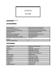
- Install placard " OPERATIONS WHICH DO NOT ENABLE EMERGENCY LANDING ON THE<br />
GROUND WITHIN 10 MINUTES AT Vy ARE PROHIBITED "<br />
. The placard will be locally manufactured in accordance with the indications of Figure 1.<br />
In case it is necessary to perform flights over such areas:<br />
- Before the next flight, perform an Eddy current check of the component, in the area of the weld, to<br />
make sure that there is no crack according to paragraph 3.B.2.<br />
- Flights are limited to 10 flying hours maximum since the last Eddy current check.<br />
- Remove during this period the placard " OPERATIONS WHICH DO NOT ENABLE EMERGENCY<br />
LANDING ON THE GROUND WITHIN 10 MINUTES AT Vy ARE PROHIBITED "<br />
- For EC225/EC725 helicopters only,<br />
. Reduce the Maximum Continuous Power (MCP) by 15% during level flights with a speed above 60 kts<br />
(IAS ≥ 60 kts) as per paragraph 3.B.1,.<br />
. Install the placard by the following one “Maximum continuous torque limited to 70% during level<br />
flights at IAS≥ 60 kts” in the full view of the pilots.<br />
- The placard will be locally manufactured in accordance with the indications of Figure 1<br />
Non-installed equipment:<br />
Not applicable.<br />
CAUTION<br />
ONLY LEVEL II AND LEVEL III OPERATORS CERTIFIED IN<br />
THE EDDY CURRENT DETECTION METHOD IN THE<br />
AERONAUTICS SECTOR ACCORDING TO THE EN4179 OR<br />
NAS410 STANDARD ARE AUTHORIZED TO CARRY OUT<br />
THE INSPECTION.<br />
MOREOVER, EACH OPERATOR HAS TO ATTEND AN<br />
ADDITIONAL TRAINING PERFORMED UNDER<br />
EUROCOPTER RESPONSIBILITY. THIS TRAINING WILL<br />
INCLUDE PRACTICING ON DEFECTS GENERATED ON<br />
REAL VERTICAL SHAFT AND ON REPRESENTATIVE<br />
COUPONS.<br />
Revision 0 2012-06-27 Page 8/15<br />
Revision 2 2012-11-21 This document is available on the internet: www.eurocopter.com/techpub
1.F. APPROVAL<br />
Approval of modifications:<br />
Not applicable.<br />
Approval of this document:<br />
<strong>EASB</strong><br />
The technical information contained in this ALERT SERVICE BULLETIN Revision 0 was approved<br />
on June 27, 2012 under the authority of EASA Design Organization Approval No. 21J.056 for helicopters of<br />
civil versions subject to an Airworthiness Certificate.<br />
For the French Government helicopters, as the content of this ALERT SERVICE BULLETIN is strictly<br />
identical to ALERT SERVICE BULLETINS AS332 No. 01.00.82 and EC225 No. 04A009 of the civil version,<br />
the technical information contained in this ALERT SERVICE BULLETIN Revision 0 was approved<br />
on June 27, 2012 under the prerogatives of the recognition of design capability FRA21J-002-DGA.<br />
The technical information contained in this ALERT SERVICE BULLETIN Revision 0 was approved<br />
on June 27, 2012 by the EUROCOPTER Airworthiness Department for export military versions.<br />
The technical information contained in this ALERT SERVICE BULLETIN Revision 1 was approved<br />
on October 24, 2012 under the authority of EASA Design Organization Approval No. 21J.056 for helicopters<br />
of civil versions subject to an Airworthiness Certificate.<br />
For the French Government helicopters, as the content of this ALERT SERVICE BULLETIN is strictly<br />
identical to ALERT SERVICE BULLETINS AS332 No. 01.00.82 and EC225 No. 04A009 of the civil version,<br />
the technical information contained in this ALERT SERVICE BULLETIN Revision 1 was approved<br />
on October 24, 2012 under the prerogatives of the recognition of design capability FRA21J-002-DGA.<br />
The technical information contained in this ALERT SERVICE BULLETIN Revision 1 was approved<br />
on October 24, 2012 by the EUROCOPTER Airworthiness Department for export military versions.<br />
The technical information contained in this ALERT SERVICE BULLETIN Revision 2 was approved<br />
on November 21, 2012 under the authority of EASA Design Organization Approval No. 21J.056 for<br />
helicopters of civil versions subject to an Airworthiness Certificate.<br />
For the French Government helicopters, as the content of this ALERT SERVICE BULLETIN is strictly<br />
identical to ALERT SERVICE BULLETINS AS332 No. 01.00.82 and EC225 No. 04A009 of the civil version,<br />
the technical information contained in this ALERT SERVICE BULLETIN Revision 2 was approved<br />
on November 21, 2012 under the prerogatives of the recognition of design capability FRA21J-002-DGA.<br />
The technical information contained in this ALERT SERVICE BULLETIN Revision 2 was approved<br />
on November 21, 2012 by the EUROCOPTER Airworthiness Department for export military versions.<br />
Revision 0 2012-06-27 Page 9/15<br />
Revision 2 2012-11-21 This document is available on the internet: www.eurocopter.com/techpub
1.G. MANPOWER<br />
EUROCOPTER recommends that compliance with this ALERT SERVICE BULLETIN is ensured by<br />
personnel with the following qualifications:<br />
Qualification: 1 Technician.<br />
The time for the operations is given for information purposes, for a standard configuration.<br />
Time for the operations: approximately 5 minutes.<br />
1.H. WEIGHT AND BALANCE<br />
Not applicable.<br />
1.I. EFFECT ON ELECTRICAL LOADS<br />
Not applicable.<br />
1.J. SOFTWARE MODIFICATION EMBODIMENT RECORD<br />
Not applicable.<br />
1.K. REFERENCES<br />
Not applicable.<br />
1.L. DOCUMENTS AFFECTED<br />
Not applicable.<br />
1.M. INTERCHANGEABILITY OR MIXABILITY OF PARTS<br />
Not applicable.<br />
<strong>EASB</strong><br />
Revision 0 2012-06-27 Page 10/15<br />
Revision 2 2012-11-21 This document is available on the internet: www.eurocopter.com/techpub
2. MATERIAL INFORMATION<br />
2.A. MATERIAL: PRICE - AVAILABILITY - PROCUREMENT<br />
Not applicable.<br />
2.B. INFORMATION CONCERNING INDUSTRIAL SUPPORT<br />
Not applicable.<br />
2.C. MATERIAL REQUIRED FOR EACH HELICOPTER/COMPONENT<br />
Not applicable.<br />
2.D. MATERIAL TO BE RETURNED<br />
Not applicable.<br />
<strong>EASB</strong><br />
Revision 0 2012-06-27 Page 11/15<br />
Revision 2 2012-11-21 This document is available on the internet: www.eurocopter.com/techpub
3. ACCOMPLISHMENT INSTRUCTIONS<br />
3.A. GENERAL<br />
Not applicable.<br />
3.B. OPERATIONAL PROCEDURE<br />
3.B.1 Reduction of the Maximum Continuous Power (MCP) by 15%<br />
<strong>EASB</strong><br />
The MGB power limitation expressed in torque is reduced from 82.7% to 70%.<br />
Consequently, the displayed FLI cannot be taken into account to control the torque limitation during level<br />
flight.<br />
The torque limitation must be controlled via the torque information available in the VMS.<br />
3.B.2 Eddy Current check procedure<br />
NOTE<br />
The use of the 4-axis Automatic Pilot remains possible.<br />
However, it must be taken into account that the Automatic<br />
Pilot will not control the new torque limitation during level<br />
flight.<br />
- Remove oil sump cover according to AMM Task 63-21-00-062 or MET Task 63.24.00.402 (“Oil Sump<br />
Cover Removal-Installation”).<br />
- Perform an Eddy current check of the bevel gear, in the area of the weld, to make sure that there is no<br />
crack, according to the procedure given by EUROCOPTER after specific training.<br />
- Re-install oil sump cover according to AMM Task 63-21-00-062 or MET Task 63.24.00.402 (“Oil Sump<br />
Cover Removal-Installation”.<br />
3.C. IDENTIFICATION<br />
CAUTION<br />
ONLY LEVEL II AND LEVEL III OPERATORS CERTIFIED IN<br />
THE EDDY CURRENT DETECTION METHOD IN THE<br />
AERONAUTICS SECTOR ACCORDING TO THE EN4179 OR<br />
NAS410 STANDARD ARE AUTHORIZED TO CARRY OUT THE<br />
INSPECTION.<br />
MOREOVER, EACH OPERATOR HAS TO ATTEND AN<br />
ADDITIONAL TRAINING PERFORMED UNDER<br />
EUROCOPTER RESPONSIBILITY. THIS TRAINING WILL<br />
INCLUDE PRACTICING ON DEFECTS GENERATED ON REAL<br />
VERTICAL SHAFT AND ON REPRESENTATIVE COUPONS.<br />
Record first compliance with this document, with the revision number, in the helicopter documents.<br />
3.D. OPERATING AND MAINTENANCE INSTRUCTIONS<br />
Not applicable.<br />
Revision 0 2012-06-27 Page 12/15<br />
Revision 2 2012-11-21 This document is available on the internet: www.eurocopter.com/techpub
LES OPERATIONS NE PERMETTANT PAS UN<br />
ATTERRISSAGE D’URGENCE AU SOL DANS LES 10<br />
MINUTES A LA Vy SONT INTERDITES<br />
OPERATIONS WHICH DO NOT ENABLE EMERGENCY<br />
LANDING ON THE GROUND WITHIN 10 MINUTES AT<br />
Vy ARE PROHIBITED<br />
COUPLE MAXIMUM CONTINU LIMITE A 70%<br />
LORS DES VOLS EN PALIER A IAS≥ 60 KTS<br />
MAXIMUM CONTINUOUS TORQUE LIMITED TO 70%<br />
DURING LEVEL FLIGHTS AT IAS≥ 60 KTS<br />
FABRICATION ETIQUETTE AUTO-<br />
ADHESIVE<br />
Hélicoptère civil<br />
- Taille des lettres : 6mm<br />
- lettres de couleur rouge sur fond blanc<br />
Hélicoptère militaire<br />
- Taille des lettres : 6mm<br />
- Lettres de couleur noire sur fond jaune<br />
Figure 1<br />
A SELF-ADHESIVE LABEL MADE LOCALLY<br />
Civil helicopter<br />
- Size of the letters: 6mm<br />
- Red letters on a white background<br />
Military helicopter<br />
- Size of the letters: 6mm<br />
- Black letters on yellow background<br />
<strong>EASB</strong><br />
Revision 0 2012-06-27 Page 13/15<br />
Revision 2 2012-11-21 This document is available on the internet: www.eurocopter.com/techpub
4. APPENDIX<br />
APPENDIX 1<br />
5.2 MGB pressure and temperature alarms<br />
Symptoms Condition Consequences and procedures<br />
on warning and<br />
caution panel<br />
+<br />
on MGB control box<br />
on warning and<br />
caution panel<br />
Procedures:<br />
Power ........................................ Reduce to obtain IAS = Vy.<br />
Procedures:<br />
........................................................................ Press.<br />
LAND IMMEDIATELY<br />
Power ........................................ Reduce to obtain IAS = Vy.<br />
LAND IMMEDIATELY<br />
3.3<br />
<strong>EASB</strong><br />
Revision 0 2012-06-27 Page 14/15<br />
Revision 2 2012-11-21 This document is available on the internet: www.eurocopter.com/techpub
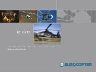
APPENDIX 2<br />
2 MAIN GEARBOX LUBRICATION SYSTEM FAILURES<br />
2.1A Failure of the vertical shaft driving the two MGB lubrication pumps<br />
Symptoms Condition Consequences and procedures<br />
Simultaneously :<br />
+<br />
+<br />
Oil pressure less than<br />
0.4 bar.<br />
+<br />
on MGB control<br />
box<br />
+<br />
.<br />
Vertical shaft<br />
driving the two<br />
MGB lubrication<br />
pumps has failed<br />
Procedure:<br />
Power............................... Reduce to obtain IAS = Vy<br />
.................................................................... Press<br />
LAND IMMEDIATELY<br />
3.7<br />
<strong>EASB</strong><br />
Revision 0 2012-06-27 Page 15/15<br />
Revision 2 2012-11-21 This document is available on the internet: www.eurocopter.com/techpub