Hotsy 5700 97-6359 0511 - ETS Company Pressure Washers and ...
Hotsy 5700 97-6359 0511 - ETS Company Pressure Washers and ...
Hotsy 5700 97-6359 0511 - ETS Company Pressure Washers and ...

Create successful ePaper yourself
Turn your PDF publications into a flip-book with our unique Google optimized e-Paper software.
Read instructions carefully before attempting to assemble, install, operate or service this pressure<br />
washer. Failure to comply with instructions could result in personal injury <strong>and</strong>/or property damage!<br />
LISTED<br />
®<br />
SERIAL NUMBER:<br />
DATE PURCHASED:<br />
NOTE: This manual is intended for use<br />
with the following model releases only:<br />
FOR SALES AND SERVICE, PLEASE CONTACT:<br />
<strong>5700</strong> Series<br />
OPERATING INSTRUCTIONS<br />
AND PARTS MANUAL<br />
S5730-3 S5730-5 S5732-4<br />
S5732-5 S5733-1 S5735-3<br />
c<br />
<strong>97</strong>-<strong>6359</strong><br />
®
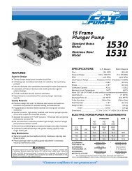
S5730-3 SPECIFICATIONS<br />
● Pump Volume At Pump Head: 8 GPM/480 GPH<br />
● Pump <strong>Pressure</strong> At Pump Head: 3000 PSI<br />
● Burner Type: Fuel Oil Fired - 768,000 BTU/Hr.<br />
● Burner Fuel <strong>Pressure</strong>: 160 PSI<br />
● Machine Voltage: 230VAC/60Hz/3Ph<br />
● Total Machine Amperage: 47 Amps<br />
● Machine Weight: 850 Lbs.<br />
● Shipping Weight: 930 Lbs.<br />
● Burner Exhaust Vent: 8"<br />
● Machine Dimensions: L=57", W=32", H=50"<br />
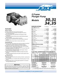
S5730-5 SPECIFICATIONS<br />
● Pump Volume At Pump Head: 8 GPM/480 GPH<br />
● Pump <strong>Pressure</strong> At Pump Head: 3000 PSI<br />
● Burner Type: Fuel Oil Fired - 768,000 BTU/Hr.<br />
● Burner Fuel <strong>Pressure</strong>: 160 PSI<br />
● Machine Voltage: 208VAC/60Hz/3Ph<br />
● Total Machine Amperage: 50 Amps<br />
● Machine Weight: 850 Lbs.<br />
● Shipping Weight: 930 Lbs.<br />
● Burner Exhaust Vent: 8"<br />
● Machine Dimensions: L=57", W=32", H=50"<br />
S5732-4 SPECIFICATIONS<br />
● Pump Volume At Pump Head: 8 GPM/480 GPH<br />
● Pump <strong>Pressure</strong> At Pump Head: 3000 PSI<br />
● Burner Type: Natural Gas Fired - 657,000 BTU/Hr.<br />
● Machine Voltage: 230VAC/60Hz/3Ph<br />
● Total Machine Amperage: 45 Amps<br />
● Machine Weight: 850 Lbs.<br />
● Shipping Weight: 930 Lbs.<br />
● Burner Exhaust Vent: 10"<br />
● Machine Dimensions: L=57", W=32", H=50"<br />
S5732-5 SPECIFICATIONS<br />
● Pump Volume At Pump Head: 8 GPM/480 GPH<br />
● Pump <strong>Pressure</strong> At Pump Head: 3000 PSI<br />
● Burner Type: Natural Gas Fired - 657,000 BTU/Hr.<br />
● Machine Voltage: 208VAC/60Hz/3Ph<br />
● Total Machine Amperage: 47 Amps<br />
● Machine Weight: 850 Lbs.<br />
● Shipping Weight: 930 Lbs.<br />
● Burner Exhaust Vent: 10"<br />
● Machine Dimensions: L=57", W=32", H=50"<br />
S5733-1 SPECIFICATIONS<br />
● Pump Volume At Pump Head: 8 GPM/480 GPH<br />
● Pump <strong>Pressure</strong> At Pump Head: 3000 PSI<br />
● Burner Type: Fuel Oil Fired - 768,000 BTU/Hr.<br />
● Burner Fuel <strong>Pressure</strong>: 160 PSI<br />
● Machine Voltage: 460VAC/60Hz/3Ph<br />
● Total Machine Amperage: 25 Amps<br />
● Machine Weight: 850 Lbs.<br />
● Shipping Weight: 930 Lbs.<br />
● Burner Exhaust Vent: 8"<br />
● Machine Dimensions: L=57", W=32", H=50"<br />
S5735-3 SPECIFICATIONS<br />
● Pump Volume At Pump Head: 8 GPM/480 GPH<br />
● Pump <strong>Pressure</strong> At Pump Head: 3000 PSI<br />
● Burner Type: Natural Gas Fired - 657,000 BTU/Hr.<br />
● Machine Voltage: 460VAC/60Hz/3Ph<br />
● Total Machine Amperage: 23 Amps<br />
● Machine Weight: 850 Lbs.<br />
● Shipping Weight: 930 Lbs.<br />
● Burner Exhaust Vent: 10"<br />
● Machine Dimensions: L=57", W=32", H=50"
4<br />
CONTENTS<br />
Important Safety Information 5-6<br />
Component Identification 7<br />
Assembly Instructions 8<br />
Installation Instructions 9-10<br />
Operating Instructions 11<br />
General Cleaning Techniques 12<br />
Storage 12<br />
Maintenance 13<br />
Troubleshooting 14-15<br />
Exploded Views 16-17<br />
Exploded View, Parts List 18-19<br />
Fuel Tank Assembly & Parts List 20-21<br />
Coil Outlet Assembly & Parts List 22<br />
Control Panel Assembly & Parts List 23-24<br />
Hose & Spray Gun Assembly & Parts List 25<br />
Gas Valve Assembly & Parts List 26-27<br />
Burner Assembly & Parts List 28<br />
Burner, Exploded View & Parts List 29-30<br />
Float Tank Assembly & Parts List 31<br />
Pump Assembly & Parts List 32-33<br />
Pump, Exploded View & Parts List 34-36<br />
Wiring Diagrams 37-42<br />
Warranty<br />
Model Number ______________________________<br />
Serial Number ______________________________<br />
Date of Purchase ____________________________<br />
The model <strong>and</strong> serial numbers will be found on a decal attached to<br />
the pressure washer. You should record both serial number <strong>and</strong><br />
date of purchase <strong>and</strong> keep in a safe place for future reference.<br />
<strong>97</strong>-<strong>6359</strong> • HOTSY <strong>5700</strong> Series • REV. 11/05
WARNING<br />
READ OPERATOR’S<br />
MANUAL<br />
THOROUGHLY<br />
PRIOR TO USE.<br />
RISK OF<br />
ASPHYXIATION.<br />
USE ONLY IN A WELL<br />
VENTILATED AREA.<br />
WARNING<br />
KEEP WATER SPRAY<br />
AWAY FROM<br />
ELECTRICAL WIRING.<br />
IMPORTANT SAFETY INFORMATION<br />
CAUTION: To reduce the risk of<br />
injury, read operating instructions<br />
carefully before using.<br />
1. Read owner's manual thoroughly.<br />
Failure to follow instructions<br />
could cause malfunction<br />
of the machine <strong>and</strong><br />
result in death, serious bodily<br />
injury <strong>and</strong>/or property damage.<br />
2. Know how to stop machine <strong>and</strong> bleed pressures<br />
quickly. Be thoroughly familiar with the controls.<br />
3. Stay alert — watch what you are doing.<br />
4. All installations must comply with local codes. Contact<br />
your electrician, plumber, utility company or<br />
the selling distributor for specific details.<br />
WARNING: Risk of asphyxiation.<br />
WARNING<br />
Use this product only in a well<br />
ventilated area.<br />
WARNING<br />
RISK OF FIRE.<br />
DO NOT ADD FUEL<br />
WHEN OPERATING<br />
MACHINE.<br />
5. When the machine is working,<br />
do not cover or place in a<br />
closed space where ventilation<br />
is not sufficient.<br />
WARNING: Risk of fire. Do not add<br />
fuel when the machine is operating.<br />
6. Risk of explosion — do not<br />
spray flammable liquids or operate<br />
in an explosive location.<br />
Operate only where open<br />
flame or torch is permitted.<br />
WARNING: Keep water spray<br />
away from electrical wiring or fatal<br />
electrical shock may result.<br />
7. To protect the operator from<br />
electrical shock, the machine<br />
must be electrically grounded.<br />
It is the responsibility of the<br />
owner to connect this machine<br />
to a UL grounded receptacle<br />
of proper voltage <strong>and</strong><br />
amperage ratings. Do not spray water on or near<br />
electrical components. Do not touch machine with<br />
wet h<strong>and</strong>s or while st<strong>and</strong>ing in water. Always disconnect<br />
power before servicing.<br />
8. Grip cleaning w<strong>and</strong> securely with both h<strong>and</strong>s before<br />
starting the cleaner. Failure to do this could<br />
result in injury from a whipping w<strong>and</strong>.<br />
WARNING<br />
HIGH PRESSURE<br />
SPRAY CAN PIERCE<br />
SKIN AND TISSUES.<br />
<strong>97</strong>-<strong>6359</strong> • HOTSY <strong>5700</strong> Series • REV. 11/05<br />
WARNING: High pressure<br />
stream of fluid that this equipment<br />
can produce can pierce<br />
skin <strong>and</strong> its underlying tissues,<br />
leading to serious injury <strong>and</strong><br />
possible amputation.<br />
9. High pressure developed by<br />
these machines can cause<br />
personal injury or equipment<br />
damage. Use caution when<br />
operating. Do not direct discharge stream at people<br />
or severe injury <strong>and</strong>/or death may result.<br />
10. Never make adjustments on machine while in operation;<br />
disconnect from electrical source or shut<br />
off gas valve.<br />
WARNING: High pressure spray<br />
WARNING<br />
can cause paint chips or other<br />
particles to become airborne<br />
<strong>and</strong> fly at high speeds.<br />
PROTECTIVE<br />
EYEWEAR AND<br />
CLOTHING MUST<br />
BE WORN.<br />
WARNING<br />
RISK OF INJURY.<br />
HOT SURFACES<br />
CAN CAUSE BURNS<br />
11.Eye, h<strong>and</strong> <strong>and</strong> foot safety devices<br />
must be worn when using<br />
this equipment.<br />
WARNING: Risk of injury. Hot<br />
surfaces can cause burns. Use<br />
only designated gripping areas<br />
of spray gun <strong>and</strong> w<strong>and</strong>. Do<br />
not place h<strong>and</strong>s or feet on noninsulated<br />
areas of the pressure<br />
washer when starting gasoline<br />
engine.<br />
12. Machines with shut-off trigger gun should not be<br />
operated with the trigger in the off position for extensive<br />
periods of time as this may cause damage<br />
to the pump.<br />
13. Protect from freezing.<br />
14. Be certain all quick coupler fittings are secured before<br />
using pressure washer.<br />
15. Do not allow acids, caustic, or abrasive fluids to<br />
pass through the pump.<br />
16. Inlet water must be from a cold, fresh city water supply.<br />
17. To reduce the risk of injury, close supervision is<br />
necessary when a machine is used near children.<br />
Do not allow children to operate the pressure<br />
washer. This machine must be attended during<br />
operation.<br />
18. The best insurance against an accident is precaution<br />
<strong>and</strong> knowledge of the machine.<br />
19. Do not operate this product when fatigued or under<br />
the influence of alcohol or drugs. Keep operating<br />
area clear of all persons.<br />
PRESSURE WASHER OPERATOR’S MANUAL<br />
5
OPERATOR’S MANUAL PRESSURE WASHER<br />
6<br />
IMPORTANT SAFETY INFORMATION<br />
20. <strong>Hotsy</strong> will not be liable for any changes made to<br />
our st<strong>and</strong>ard machines, or any components not<br />
purchased from <strong>Hotsy</strong>.<br />
21. Do not overreach or st<strong>and</strong> on unstable support.<br />
Keep good footing <strong>and</strong> balance at all times.<br />
22. Follow maintenance instructions specified in<br />
manual.<br />
23. Cleaning area should be provided with adequate<br />
slopes <strong>and</strong> drainage to reduce possibility of falls<br />
because of slippery surfaces.<br />
24. Turn burner off <strong>and</strong> cool to 100°F before turning<br />
machine off.<br />
25. Extinguish any open flame, <strong>and</strong> test all joints with<br />
a soap solution. If the odor persists, call your gas<br />
supplier immediately.<br />
26. Use extreme caution when moving pressure<br />
washer over rough or uneven surfaces.<br />
27. When applying detergents follow the safety rules<br />
on the detergent label. Use detergent from a covered<br />
D.O.T. approved container.<br />
28. This machine has been provided with Warning <strong>and</strong><br />
Instruction decals for the safety of the operator. If<br />
these decals are removed or become damaged<br />
they should be replaced. Contact your dealer for<br />
replacement decals.<br />
<strong>97</strong>-<strong>6359</strong> • HOTSY <strong>5700</strong> Series • REV. 11/05
Hose<br />
Hanger<br />
Garden Hose<br />
(Not Included)<br />
Fresh Water<br />
Inlet<br />
COMPONENT IDENTIFICATION<br />
Burner Exhaust<br />
Vent<br />
High<br />
<strong>Pressure</strong> Hose<br />
Float Tank<br />
Fuel Supply<br />
(Oil Fired Models)<br />
Trigger Gun<br />
<strong>97</strong>-<strong>6359</strong> • HOTSY <strong>5700</strong> Series • REV. 11/05<br />
Detergent Control<br />
Nozzles<br />
Thermostat<br />
W<strong>and</strong><br />
Burner Switch<br />
Pump<br />
Switch<br />
Detergent Bucket (Not<br />
Included)<br />
High<br />
<strong>Pressure</strong> Nozzle<br />
PRESSURE WASHER OPERATOR’S MANUAL<br />
7
OPERATOR’S MANUAL PRESSURE WASHER<br />
8<br />
Unpacking<br />
Unpack carefully. Wear safety glasses or goggles while<br />
unpacking, assembling, or operating pressure washer. If<br />
there are missing components or hidden damage,<br />
immediately contact carrier concerning discrepancies.<br />
1. Remove the two bolts that secure the pressure washer<br />
to the pallet.<br />
2. Remove pressure washer from pallet.<br />
Parts Included<br />
<strong>Pressure</strong> Washer<br />
<strong>Pressure</strong> Hose<br />
W<strong>and</strong><br />
Trigger Gun<br />
Hose Hangers (2 Ea.)<br />
Parts Bag Containing:<br />
■ Reducer Bushing<br />
■ <strong>Pressure</strong> Nozzles (3 Ea.)<br />
■ Adapter Nipple<br />
■ Adapter Nut<br />
■ Hose Clamp<br />
■ Quick Disconnects (2 Ea.)<br />
■ Garden Hose Gasket<br />
■ Spring<br />
■ Quick Disconnect Plug<br />
■ Detergent Screen<br />
Operating Instructions <strong>and</strong> Parts Manual<br />
Oil Burner Manual<br />
Tools Required<br />
10" Adjustable Wrenches (2 Ea.)<br />
Teflon Tape<br />
Hose Hanger<br />
1. Install hose hangers on coil tank as shown in<br />
Figure 1.<br />
Hose Hanger<br />
Figure 1 - Hose Hanger Installation<br />
ASSEMBLY INSTRUCTIONS<br />
Float Tank<br />
<strong>97</strong>-<strong>6359</strong> • HOTSY <strong>5700</strong> Series • REV. 11/05<br />
<strong>Pressure</strong> Hose, Trigger Gun <strong>and</strong> W<strong>and</strong><br />
1. When assembling, use teflon tape on all plumbing<br />
connections to prevent leakage.<br />
2. Install the pressure hose on the pressure washer as<br />
shown in Figure 2.<br />
<strong>Pressure</strong> Hose<br />
Figure 2 - <strong>Pressure</strong> Hose Installation<br />
3. Assemble w<strong>and</strong> components as shown in Figure 3.<br />
<strong>Pressure</strong> Hose<br />
NOTE: The pressure nozzle is not to be installed at<br />
this time.<br />
4. Install garden hose adapter on float tank as shown in<br />
Figure 4.<br />
Garden Hose (Not<br />
Included)<br />
W<strong>and</strong><br />
Trigger Gun<br />
Figure 3 - Trigger Gun/W<strong>and</strong> Assembly<br />
Figure 4 - Float Tank/Garden Hose Adapter<br />
5. Make sure all plumbing connections are tight.<br />
Rupture<br />
Disk<br />
Quick<br />
Disconnect
Getting Started<br />
IMPORTANT: Proper initial installation of equipment<br />
will assure more satisfactory performance, longer service<br />
life, <strong>and</strong> lower maintenance cost.<br />
IMPORTANT: The use of a backflow preventer on the<br />
water supply hose is recommended <strong>and</strong> may be<br />
required by local code.<br />
The pressure washer should be run on a level surface<br />
<strong>and</strong> in a protected area where it is not readily influenced<br />
by outside forces such as strong winds, freezing<br />
temperatures, rain, etc. The pressure washer should be<br />
located to assure easy access for filling of fluids,<br />
adjustments <strong>and</strong> maintenance. Normal precautions should<br />
be taken by the operator to prevent moisture from reaching<br />
the pressure washer. It is recommended that a partition<br />
be made between the wash area <strong>and</strong> the pressure washer<br />
to prevent direct spray from the w<strong>and</strong> from coming in<br />
contact with the pressure washer. Moisture reaching the<br />
equipment will reduce the pressure washer’s service life.<br />
All installations must comply with the local codes covering<br />
such installations.<br />
Electrical<br />
WARNING: Make sure all switches <strong>and</strong> controls are in<br />
the OFF position prior to connecting electrical supply.<br />
WARNING: DO NOT st<strong>and</strong> in water while connecting<br />
<strong>and</strong> disconnecting electrical supply.<br />
IMPORTANT: Consult local building codes for exact<br />
electrical requirements. Licensed contractors may be<br />
required.<br />
Power In<br />
Figure 5 - Wiring Connections<br />
INSTALLATION INSTRUCTIONS<br />
The <strong>5700</strong> Series is designed for connection to an overload<br />
protected grounded circuit. It is recommended this circuit<br />
be protected by a UL approved ground fault circuit<br />
interrupter (GFCI). An electrical disconnect must be<br />
provided in this circuit. All wiring must be of proper voltage<br />
<strong>and</strong> amperage rating <strong>and</strong> conform to applicable codes.<br />
Refer to Figure 5 for wiring connections. A hole has been<br />
provided in the control box for attachment of 1 inch<br />
electrical conduit.<br />
For proper operation the motor rotation is to be<br />
counterclockwise as viewed looking towards the rear of<br />
the motor (opposite pump attachment). If the rotation is<br />
incorrect, interchange any two of the power supply<br />
connections to reverse rotation.<br />
Venting<br />
DANGER: DO NOT run machine indoors or in an<br />
enclosed area without proper ventilation, as exhaust<br />
fumes may be hazardous to your health.<br />
DANGER: DO NOT operate machine in areas where<br />
flammable vapors (gasoline, solvents, etc.) may be<br />
present, as this machine may ignite the vapors.<br />
CAUTION: All venting must be in accordance with<br />
applicable federal <strong>and</strong> state laws, <strong>and</strong> local ordinances.<br />
This machine is not to be connected to a type B gas<br />
vent. Consult local heating contractors.<br />
If the pressure washer is to be used in an enclosed area,<br />
a flue must be installed to vent burner exhaust to the<br />
outside atmosphere. Be sure the flue is the same size as<br />
the burner exhaust vent on the pressure washer lid. Poor<br />
draft will cause the pressure washer to soot <strong>and</strong> not<br />
operate properly. When selecting the location for<br />
installation, beware of poorly ventilated locations or areas<br />
where exhaust fans may cause an insufficient supply of<br />
oxygen. Proper combustion can only be obtained when<br />
there is a sufficient supply of oxygen available for the<br />
amount of fuel being burned. If it is necessary to install<br />
the machine in a poorly ventilated area, outside fresh air<br />
may have to be piped to the burner <strong>and</strong> a fan installed to<br />
bring sufficient air into the machine. Locate the pressure<br />
washer so that the flue will be as straight as possible <strong>and</strong><br />
protrude through the roof at a proper height <strong>and</strong> location<br />
to provide adequate draft. This oil fired pressure washer<br />
must have a draft regulator installed in the flue (available<br />
from most heating contractors). A draft regulator will permit<br />
proper upward flow of exhaust flue gases.<br />
Oil Burner<br />
Burner Air Adjustment: The oil burner is preset <strong>and</strong><br />
performance tested at the factory (elevation 500 feet). A<br />
onetime initial correction of the burner for your location<br />
will pay off in economy, performance, <strong>and</strong> extended<br />
service life.<br />
To adjust, start machine <strong>and</strong> turn burner ON (refer to<br />
Operation for details). Loosen locking screw (refer to<br />
Figure 6) <strong>and</strong> close air b<strong>and</strong> until black smoke appears<br />
from burner exhaust vent. Note air b<strong>and</strong> position. Next,<br />
<strong>97</strong>-<strong>6359</strong> • HOTSY <strong>5700</strong> Series • REV. 11/05<br />
PRESSURE WASHER OPERATOR’S MANUAL<br />
9
OPERATOR’S MANUAL PRESSURE WASHER<br />
10<br />
slowly open the air b<strong>and</strong> until white smoke just starts to<br />
appear. Turn air b<strong>and</strong> halfway back to the black smoke<br />
position previously noted. Tighten locking screw.<br />
Air B<strong>and</strong><br />
Air Adjustment<br />
Screw<br />
Figure 6 - Burner Adjustment<br />
CAUTION: If white smoke appears from burner<br />
exhaust vent during start-up or operation, discontinue<br />
use <strong>and</strong> readjust air b<strong>and</strong>s.<br />
NOTE: If a flue is installed, have a professional serviceman<br />
adjust your burner for a #1 or #2 smoke spot<br />
on the Bacharach scale.<br />
For additional burner information, refer to Oil Burner<br />
Manual provided with this pressure washer.<br />
Gas Burner<br />
CAUTION: Have a qualified gas serviceman install <strong>and</strong><br />
service your equipment.<br />
WARNING: Gas line supply pressure must not exceed<br />
14 water column inches (.50 PSI).<br />
IMPORTANT: Gas line must be provided with a shut<br />
off valve.<br />
IMPORTANT: The gas supply must be able to supply a<br />
minimum of 525,000 BTU/HR at the machines rated<br />
manifold pressure.<br />
Consult building codes for installation requirements.<br />
For proper <strong>and</strong> safe machine operation, we recommend<br />
that a licensed contractor be consulted for machine<br />
installation.<br />
INSTALLATION INSTRUCTIONS<br />
<strong>Pressure</strong><br />
Adjustment<br />
Screw<br />
Natural Gas Fuel<br />
<strong>97</strong>-<strong>6359</strong> • HOTSY <strong>5700</strong> Series • REV. 11/05<br />
Have a qualified gas serviceman install the natural gas<br />
fuel supply line to the machine. See Figure 7 for location<br />
of gas inlet.<br />
Gas Valve<br />
Inlet View<br />
Outlet View<br />
Fuel Pump Figure 7 - Gas Valve <strong>and</strong> Regulator Side View<br />
The ideal incoming gas pressure is 11 w.c.i. (water<br />
column inches) minimum 6 w.c.i., maximum 14 w.c.i. or<br />
1/2 psig. The correct operating manifold pressure for<br />
natural gas is 3.5 w.c.i. The operating manifold pressure<br />
for propane gas is 11 w.c.i. The gas valve pressure<br />
regulator can be adjusted between 3 <strong>and</strong> 4 w.c.i. natural<br />
gas or 6 <strong>and</strong> 11 w.c.i. for propane.<br />
The gas pressure coming out of the regulator <strong>and</strong> going<br />
to the burner ring has been factory set. You should not<br />
readjust the burner ring gas pressure. If you replace your<br />
gas valve, you will need to adjust the new valve. Refer<br />
to your machine’s specification plate for the correct<br />
pressure setting. Follow the installation <strong>and</strong> adjustment<br />
instructions provided with your replacement valve.
Before Starting<br />
1. Read all manuals provided with this pressure washer.<br />
Become familiar with location <strong>and</strong> function of all<br />
operating <strong>and</strong> safety controls.<br />
2. Check pump oil level.<br />
WARNING: Check hoses, fittings, w<strong>and</strong>, trigger gun<br />
<strong>and</strong> fuel connections daily for signs of wear, cracks<br />
<strong>and</strong> looseness, <strong>and</strong> replace as required.<br />
3. Connect water supply hose to the garden hose connector<br />
located on the float tank. The water faucet<br />
<strong>and</strong> supply hose must be capable of providing a minimum<br />
of 8.0 gallons per minute (GPM).<br />
4. Fill oil burner fuel tank. Use kerosene, #1 grade home<br />
heating oil, #1 or #2 diesel fuel. DO NOT USE GASO-<br />
LINE, CRANKCASE OIL DRAININGS, OR WASTE<br />
OIL.<br />
5. If detergents are to be used, only use detergents<br />
intended for pressure washers. Follow instructions<br />
on the detergent container.<br />
IMPORTANT: Before installing nozzle on initial startup,<br />
turn on the water supply <strong>and</strong> pump switch <strong>and</strong><br />
allow water to run from the end of the w<strong>and</strong> until<br />
clear to prevent the nozzle from clogging.<br />
IMPORTANT: If the pressure washer has not been<br />
used for an extended period of time, remove the<br />
nozzle from the end of the w<strong>and</strong> <strong>and</strong> turn on water<br />
supply <strong>and</strong> pump switch. Allow water to run from<br />
the end of the w<strong>and</strong> until clear.<br />
6. Install the proper pressure nozzle on end of w<strong>and</strong> for<br />
your cleaning needs, refer to Figure 8.<br />
Manual Trigger Lock<br />
OPERATION INSTRUCTIONS<br />
<strong>Pressure</strong> Nozzle<br />
Figure 8 - Nozzle Installation/Manual Trigger Lock<br />
IMPORTANT: The trigger gun provided with this pressure<br />
washer is equipped with a manual trigger lock<br />
to prevent accidental operation of the trigger gun,<br />
refer to Figure 9. The trigger lock should be used<br />
whenever the trigger gun is not in use.<br />
To Start<br />
<strong>97</strong>-<strong>6359</strong> • HOTSY <strong>5700</strong> Series • REV. 11/05<br />
DANGER: DO NOT point w<strong>and</strong> or trigger gun at yourself<br />
or at any person. Bodily injury may result from<br />
water under high pressure.<br />
WARNING: Wear eye, ear, h<strong>and</strong>, foot <strong>and</strong> skin protection<br />
at all times while operating pressure washer.<br />
IMPORTANT: The water must be turned on before starting.<br />
Running the pump dry will cause damage <strong>and</strong> void<br />
warranty.<br />
IMPORTANT: DO NOT allow the machine to run with<br />
trigger of the trigger gun released for more than<br />
10 minutes at any one time or damage to pump may<br />
occur.<br />
1. Turn ON water supply.<br />
2. Hold w<strong>and</strong> firmly, release trigger of trigger gun <strong>and</strong><br />
press pump start switch. Squeeze trigger of trigger<br />
gun <strong>and</strong> allow air to purge from system.<br />
3. If HOT water is desired, adjust the thermostat to the<br />
proper temperature <strong>and</strong> turn burner switch ON. The<br />
burner will light immediately with a small puff of smoke.<br />
You may need to initially adjust your burner for peak<br />
performance. See Oil Burner section under Installation.<br />
If smoke continues, refer to the Oil Burner Manual<br />
(P/N 783879) provided with this pressure washer or<br />
contact Customer Service at 1-303-792-5200. When<br />
the trigger of the trigger gun is released or when the<br />
thermostat temperature setting is reached, the burner<br />
will automatically turn off.<br />
To Stop<br />
1. If detergents were used, draw clear water through the<br />
detergent inlet line to purge detergent. Failure to do<br />
so may clog detergent metering valve.<br />
2. If burner was used, turn OFF burner switch <strong>and</strong> allow<br />
pump to run cold water through coil for several minutes.<br />
3. Press pump STOP switch.<br />
4. Turn water supply OFF.<br />
5. Squeeze trigger of trigger gun to relieve system<br />
pressure.<br />
PRESSURE WASHER OPERATOR’S MANUAL<br />
11
OPERATOR’S MANUAL PRESSURE WASHER<br />
12<br />
GENERAL CLEANING TECHNIQUES & STORAGE<br />
CLEANING TECHNIQUES<br />
Pre-rinse cleaning surface with fresh water. Place detergent<br />
suction tube directly into cleaning solution <strong>and</strong><br />
apply to surface at low pressure (for best results, limit<br />
your work area to sections approximately 6 feet square<br />
<strong>and</strong> always apply detergent from bottom to top). Allow<br />
detergent to remain on surface 1-3 minutes. Do not<br />
allow detergent to dry on surface. If surface appears to<br />
be drying, simply wet down surface with fresh water. If<br />
needed, use brush to remove stubborn dirt. Rinse at<br />
high pressure from top to bottom in an even sweeping<br />
motion keeping the spray nozzle approximately 1 foot<br />
from cleaning surface. Use overlapping strokes as you<br />
clean <strong>and</strong> rinse any surface. For best surface cleaning<br />
action spray at a slight angle.<br />
Recommendations:<br />
• Before cleaning any surface, an inconspicuous<br />
area should be cleaned to test spray pattern <strong>and</strong><br />
distance for maximum cleaning results.<br />
• If painted surfaces are peeling or chipping, use<br />
extreme caution as pressure washer may remove<br />
the loose paint from the surface.<br />
• Keep the spray nozzle a safe distance from the surface<br />
you plan to clean. High pressure wash a small<br />
area, then check the surface for damage. If no damage<br />
is found, continue to pressure washing.<br />
CAUTION - Never use:<br />
• Bleach, chlorine products <strong>and</strong> other corrosive<br />
chemicals<br />
• Liquids containing solvents (i.e., paint thinner,<br />
gasoline, oils)<br />
• Tri-sodium phosphate products<br />
• Ammonia products<br />
• Acid-based products<br />
These chemicals will harm the machine <strong>and</strong> will damage<br />
the surface being cleaned.<br />
<strong>97</strong>-<strong>6359</strong> • HOTSY <strong>5700</strong> Series • REV. 11/05<br />
RINSING<br />
It will take a few seconds for the detergent to clear.<br />
Apply safety latch to spray gun. Select <strong>and</strong> install desired<br />
high pressure nozzle. NOTE: You can also stop<br />
detergent from flowing by removing detergent siphon<br />
tube from bottle.<br />
STORAGE<br />
DANGER: DO NOT store flammable liquids (gasoline,<br />
diesel fuel, solvents, etc.) near pressure washer, or<br />
in non-ventilated areas.<br />
Protect from freezing by storing in a heated area, or by<br />
flushing the system with antifreeze (use an automotive<br />
engine antifreeze or windshield washer solvent to<br />
antifreeze). To flush the system fill the float tank with<br />
antifreeze <strong>and</strong> remove pressure nozzle from w<strong>and</strong>. Start<br />
the machine <strong>and</strong> allow it to run until antifreeze flows from<br />
the end of the w<strong>and</strong>. Place end of w<strong>and</strong> into float tank<br />
<strong>and</strong> circulate the antifreeze through system for several<br />
minutes. Squeeze <strong>and</strong> release the trigger of the trigger<br />
gun several times to antifreeze the unloader system. Also<br />
draw antifreeze through the detergent inlet line to<br />
antifreeze the detergent system. For added protection<br />
after antifreezing, disconnect the pressure hose from<br />
machine <strong>and</strong> remove the coil drain plug (refer to Figure<br />
12 Item 15 for location). After coil has drained, replace<br />
pressure hose <strong>and</strong> coil drain plug. If the pressure washer<br />
is not to be used for an extended length of time, it is<br />
recommended that the system be flushed with antifreeze<br />
for rust protection.
WARNING: Unauthorized machine modification or<br />
use of non-approved replacement parts may cause<br />
personal injury <strong>and</strong>/or property damage <strong>and</strong> will<br />
void the manufacturer warranty.<br />
Pump<br />
Lubrication: To lubricate pump, use 30W non-detergent<br />
oil for pump crankcase. Crankcase must be filled to<br />
center of sight glass window found on the rear of the<br />
pump, refer to Figure 9. During the break-in-period,<br />
make sure the oil is changed after the first 25 hours of<br />
operation. After that, replace oil every 3 months or 300<br />
hours of operation, whichever comes first.<br />
Sight Glass<br />
Figure 9 - Pump Lubrication<br />
Proper Pump Care:<br />
DO NOT pump acids.<br />
DO NOT allow pump to run dry.<br />
Winterize if storing in freezing temperatures, refer<br />
to Storage for details.<br />
Use a water softener on the water system if known<br />
to be high in mineral content.<br />
Use only high quality detergents <strong>and</strong> follow manufacturer’s<br />
mix recommendations.<br />
Flush the system with clear water immediately<br />
after using detergent solutions.<br />
Clean filter screen on detergent inlet line periodically.<br />
Flush the pressure washer system with antifreeze<br />
if storing for an extended period of time, refer to<br />
Storage to details.<br />
Pump Motor<br />
Oil Fill<br />
Inspect the pump motor at regular intervals. The exterior<br />
of the motor should be kept free of dirt, oil, grease,<br />
water, etc. Keep all ventilation openings free from debris.<br />
If the motor is equipped with grease fittings, lubricate<br />
the motor after every 1000 hours of operation with<br />
Chevron SRI #2 lubricant or equivalent. If the motor is<br />
not equipped with grease fittings, the pump motor<br />
bearings are permanently lubricated <strong>and</strong> will not require<br />
any additional lubrication.<br />
MAINTENANCE<br />
Oil Burner<br />
<strong>97</strong>-<strong>6359</strong> • HOTSY <strong>5700</strong> Series • REV. 11/05<br />
Refer to Oil Burner Manual provided with this pressure<br />
washer for recommended maintenance.<br />
Relief Valve<br />
WARNING: The relief valve on this pressure washer<br />
has been factory set <strong>and</strong> sealed <strong>and</strong> is a field nonadjustable<br />
part. Tampering with the factory setting may<br />
cause personal injury <strong>and</strong>/or property damage, <strong>and</strong><br />
will void the manufacturer warranty.<br />
Unloader Valve<br />
WARNING: The unloader valve on this pressure<br />
washer has been factory set <strong>and</strong> sealed <strong>and</strong> is a field<br />
nonadjustable part. Tampering with the factory setting<br />
may cause personal injury <strong>and</strong>/or property damage,<br />
<strong>and</strong> will void the manufacturer warranty.<br />
Burner Fuel Filter (Oil fired models only)<br />
Drain any water which has accumulated in fuel filter<br />
<strong>and</strong> clean or replace filter element as needed.<br />
Heating Coil<br />
Coil Descaling: In hard water areas, scale buildup within<br />
the heating coil will occur. Scale deposits will decrease<br />
the water temperature rise <strong>and</strong> may eventually clog the<br />
heating coil. Contact your local service center when<br />
descaling is needed.<br />
Coil Desooting: Poor grades of fuel oil or inadequate<br />
combustion air will cause heavy soot buildup on the<br />
outside surface of the heating coil. These deposits will<br />
insulate the coil. This will restrict the air flow through the<br />
coil, further aggravating the soot buildup. Contact your<br />
local service center when desooting is needed.<br />
PRESSURE WASHER OPERATOR’S MANUAL<br />
13
PRESSURE WASHER Troubleshooting Guide<br />
14<br />
TROUBLESHOOTING<br />
SYMPTOM POSSIBLE CAUSES CORRECTIVE ACTION<br />
<strong>Pressure</strong> washer will<br />
not run.<br />
<strong>Pressure</strong> washer runs<br />
but won't spray.<br />
Low spray pressure at<br />
nozzle.<br />
Pump not running. Press pump START switch.<br />
Power supply turned OFF to<br />
machine.<br />
Fuese blown or circuit breaker<br />
tripped in electrical supply line.<br />
<strong>97</strong>-<strong>6359</strong> • HOTSY <strong>5700</strong> Series • REV. 11/05<br />
Turn ON power supply.<br />
Replace fuse or reset circuit breaker,<br />
use only circuits of adequate capacity.<br />
Motor circuit overload tripped. Allow sufficient time for motor to cool<br />
down. Depress reset button on motor<br />
starter enclosure.<br />
Trigger of trigger gun released. Squeeze trigger.<br />
Water supply not turned ON. Open water supply valve.<br />
Clogged nozzle. Clean nozzle opening.<br />
Inlet water screen clogged. Clean.<br />
Pump sucking air. Fill the detergent container. Check for<br />
loose hose clamps or fitting.<br />
Inadequate water supply. Fully open faucet. Check for kinked or<br />
damaged hose. Use 5/8 inch minimum<br />
hose. Check for debris clogging<br />
inlet screen.<br />
Water nozzle worn or incorrect size. Replace water nozzle.<br />
Partially clogged or damaged<br />
nozzle.<br />
Uneven spray pattern. Partially clogged or damaged<br />
nozzle.<br />
<strong>Pressure</strong> washer will not<br />
produce hot water.<br />
Clean or replace.<br />
Pump sicking air. Fill the detergent container. Check for<br />
loose hose clamps or fittings.<br />
Clean or replace.<br />
Burner switch in OFF position. Place switch in ON position.<br />
Inadequate fuel supply. Oil Fired: Refill fuel tank. Use only<br />
recom-mended fuels. Refer to Before<br />
Starting under Operation.<br />
Inadequate fuel supply. Gas Fired: Check incoming service<br />
line.<br />
Pump motor not running. Pump motor must be running before<br />
burner will light.<br />
Inadequate water supply. Fully open faucet. Check for kinked or<br />
damaged hose. Use 5/8 inch minimum<br />
hose. Check for debris clogging<br />
inlet screen.<br />
Trigger of trigger gun released. Squeeze trigger. Water must be spraying<br />
for burner to light.
TROUBLESHOOTING<br />
SYMPTOM POSSIBLE CAUSES CORRECTIVE ACTION<br />
Poor or no detergent flow. Inadequate detergent supply. Refill detergent container. Ensure that<br />
pick-up screen is fully immersed.<br />
Detergent screen or hose clogged. Clean. Always start with a clean detergent<br />
container.<br />
Detergent metering valve no<br />
opening.<br />
Air being drawn through detergent<br />
inlet line.<br />
Poor cleaning. Improper detergent concentration or<br />
mixing.<br />
When ordering from your dealer, please provide the following:<br />
Model Number: S5730-3, S5730-5, S5732-4, S5732-5, S5733-1,<br />
S5735-3<br />
Machine Serial Number: ________________________________<br />
Component Part Number: ______________________________<br />
Description: __________________________________________<br />
5733 OPTIONAL EQUIPMENT<br />
292699 Portagear Kit (Oil fired models only)<br />
<strong>97</strong>-<strong>6359</strong> • HOTSY <strong>5700</strong> Series • REV. 11/05<br />
Check that h<strong>and</strong>le is not slipping on<br />
shaft.<br />
Fill the detergent container. Check for<br />
loose hose clamps or fittings.<br />
Mix detergent per manufacturer's<br />
instructions. Ensure that powdered<br />
detergents are fully dissolved.<br />
Wrong detergent for the application. Select appropriate detergent.<br />
Rinsing with hot water. A final rinse with cold water will reduce<br />
water spotting.<br />
IMPORTANT<br />
If the pressure washer demonstrates other symptoms or the corrective actions<br />
listed do not correct the problem, contact the local authorized <strong>Hotsy</strong> Service<br />
Center. The <strong>Hotsy</strong> Service Center can be identified by visiting www.hotsy.com or<br />
by calling 1-800-525-1<strong>97</strong>6.<br />
PRESSURE WASHER Troubleshooting Guide<br />
15
OPERATOR’S MANUAL PRESSURE WASHER<br />
16<br />
23,14<br />
14<br />
54<br />
21<br />
1<br />
24<br />
Grounding Lug<br />
(Enlarged View)<br />
17<br />
3<br />
12,13<br />
11<br />
9<br />
6<br />
14<br />
8<br />
See<br />
Coil Outlet<br />
Illus. For<br />
Detail<br />
For<br />
Detail See<br />
Burner<br />
Assy.<br />
18<br />
70<br />
15<br />
16<br />
2<br />
71<br />
20<br />
32<br />
22<br />
EXPLODED VIEW<br />
5<br />
10<br />
61<br />
19<br />
See<br />
Float Tank<br />
Illus. For<br />
Detail<br />
7<br />
67<br />
See<br />
Fuel Tank<br />
Illus. For<br />
Detail<br />
Intermittent<br />
Ignition Unit<br />
Transformer<br />
See<br />
Fuel Tank<br />
Illus. For<br />
Detail<br />
<strong>97</strong>-<strong>6359</strong> • HOTSY <strong>5700</strong> Series • REV. 11/05<br />
4<br />
25<br />
71, 38<br />
29<br />
64<br />
66<br />
See<br />
Control Panel<br />
Illus. For<br />
Detail<br />
69<br />
30<br />
63<br />
65<br />
Coil<br />
Inlet<br />
Plumbing<br />
31<br />
33<br />
Power<br />
In<br />
28<br />
14<br />
62<br />
37<br />
36<br />
26, 27
42<br />
44<br />
46<br />
53<br />
45<br />
43<br />
EXPLODED VIEW<br />
To Coil<br />
Intlet<br />
36<br />
56<br />
55<br />
37<br />
41<br />
40<br />
39<br />
36 37<br />
34<br />
35<br />
<strong>97</strong>-<strong>6359</strong> • HOTSY <strong>5700</strong> Series • REV. 11/05<br />
14<br />
58<br />
57<br />
51<br />
47<br />
48<br />
For<br />
Detail<br />
See Pump<br />
Assy.<br />
Illus.<br />
71, 38<br />
59<br />
60<br />
52<br />
68<br />
49<br />
50<br />
14<br />
14<br />
PRESSURE WASHER OPERATOR’S MANUAL<br />
17
OPERATOR’S MANUAL PRESSURE WASHER<br />
18<br />
EXPLODED VIEW - PARTS LIST<br />
ITEM PART NO. DESCRIPTION QTY<br />
1 95-0710375367 Chassis 1<br />
2 254429 Heater Door 1<br />
3 351438 Rear Cover 1<br />
4 241366 Top Cover (Gas Fired) 1<br />
241772 Top Cover (Oil Fired) 1<br />
5 296391 Lid, 24" 1<br />
6 296382 Lid, 22-1/2" (5730-3, 5730-5, 5730-1) 1<br />
7 11-3510 Label 1<br />
8 287989 Insulation, 1" x 24" x 30" 1<br />
9 287985 Insulation, 24" x 24" 1<br />
10 240860 Coil, Oil, 22" 1<br />
240861 Coil, Gas, 22" 1<br />
11 227828 Bracket, Coil 4<br />
12 703107 Flange Nut, 5/16" - 18 8<br />
13 227828 Bracket, Coil 4<br />
14 935265 Screw, #12 - 14 x 3/4" 59<br />
15 110140 Bushing Reducer 1<br />
16 801139 Garden Hose Connector 1<br />
17 875575 Spring 1<br />
18 856025 Garden Hose Gasket 1<br />
19 914903 <strong>Hotsy</strong> Logo Plate 1<br />
20 834154 Decal, Caution Winterize 1<br />
21 11-01002 Label, Max Inlet <strong>Pressure</strong> (S5732-4, S5732-5,<br />
S5735-3 Only) 1<br />
22 11-10480 Decal, Electrical Instr. (S5732-4, S5732-5,<br />
S5735-3) 1<br />
10-07993 Decal, Electrical Instr. (S5730-3, S5730-5,<br />
S5733-1) 1<br />
23 6-0507 Ground Lug 1<br />
24 833858 Decal, Caution 1<br />
25 960181 Transformer (S5733-1 Only) 1<br />
26 615308 Box, Junction 3 Hole, 3/4” 1<br />
27 826610 Cover, Metal, 2" x 4", Wtrprf 1<br />
28 6-0517 Strain Relief, 3/4", 3303 2<br />
29 90-1<strong>97</strong>11 Bolt, 1/4" - 20 x 1/2" (Oil Fired Only) 2<br />
30 703106 Flange Nut, 1/4" - 20 (Oil Fired Only) 2<br />
31 351446 Mounting Bracket 1<br />
32 10-09003 Decal, Water Inlet 1<br />
33 612950 Bolt, 5/16" x 1" 4<br />
34 859806 Grommet, 2-1/8" x 2-7/8" x 7/16" 1<br />
35 891041 Mount, Rubber, 60 Duro 10<br />
36 703146 Nut, 3/8" ESNA 24<br />
37 780562 Washer, 3/8" SAE Flat 24<br />
38 90-50048 Latch 2<br />
39 780455 Washer, 1/2" Flat 12<br />
<strong>97</strong>-<strong>6359</strong> • HOTSY <strong>5700</strong> Series • REV. 11/05
EXPLODED VIEW - PARTS LIST<br />
ITEM PART NO. DESCRIPTION QTY<br />
40 703157 Nut, 1/2" - 13 Hex Lock, Nylon 8<br />
41 784027 Motor, 15HP/208-230-460/60Hz 1<br />
42 815137 Bushing, P1 x 1-5/8" 1<br />
43 5-522125 Bushing, P1 x 25mm 1<br />
44 830130 Pulley, 3TB50, P1 1<br />
45 830134 Pulley, 3TB64, P1 1<br />
46 616006 Belt, BX32 3<br />
47 351709 Side Cover 1<br />
48 2-01042 Grommet 1<br />
49 2-01401 Ring, Snap 1<br />
50 834159 Decal, <strong>Hotsy</strong> Detergent 1<br />
51 254425 Left Door 1<br />
52 254428 Right Door 1<br />
53 95-07104996 Base, Pump/Motor, Weldment 1<br />
54 861644 Hanger, Hose 2<br />
55 613025 Bolt, 1/2" x 5" 1<br />
56 90-4004 Washer, 1/2" SAE, Flat 1<br />
57 780482 Washer, 1/2" Lock 1<br />
58 90-20082 Nut, 1/2" Hex 1<br />
59 646663 Label, Warning: Exposed Pulleys 1<br />
60 9.800-049.0 Label, Manufacturer Cleaning Solution 1<br />
61 646673 Label, Hot Water Outlet 1<br />
62 646155 Label, Ground 1<br />
63 698256 Nipple, 1/2" x 4-1/2" Galvanized 1<br />
64 754717 Tee, 1/2" Female, Steel 1<br />
65 2-0052 Nipple, 1/2" JIC x 1/2" Pipe 1<br />
66 715755 Plug, 1/2" Square Head 1<br />
67 104928 Ring, Insulation Retainer 1<br />
68 10-02016 Label, Incoming Power 1<br />
69 703107 Nut, 5/16" Whiz Loc 4<br />
70 10-02025A Label, Caution Hot 2<br />
71 90-5000 Rivet 8<br />
<strong>97</strong>-<strong>6359</strong> • HOTSY <strong>5700</strong> Series • REV. 11/05<br />
PRESSURE WASHER OPERATOR’S MANUAL<br />
19
OPERATOR’S MANUAL PRESSURE WASHER<br />
20<br />
6<br />
10<br />
11<br />
12<br />
5<br />
FUEL TANK ASSEMBLY<br />
10<br />
11<br />
3<br />
6<br />
7<br />
8<br />
FUEL TANK PARTS LIST<br />
ITEM PART NO. DESCRIPTION QTY<br />
1 95-0710226775 Fuel Tank 1<br />
2 817358 Fuel Tank Cap 1<br />
3 867368 Hose 1/4" Black 30"<br />
4 715744 ▲ Pipe Plug 3/8" 1<br />
5 851140 ✪ Fuel Filter 1<br />
6 644752 Elbow 2<br />
7 698214 Pipe Nipple 3/8" x 5" 1<br />
8 6<strong>97</strong>931 Nipple 3/8" x Close 1<br />
9 <strong>97</strong>1407 Ball Valve 1<br />
10 698023 Hose Nipple 3/8" x 1/4" 2<br />
11 823988 Clamp 4<br />
12 867368 Hose, 1/4" Black 24"<br />
<strong>97</strong>-<strong>6359</strong> • HOTSY <strong>5700</strong> Series • REV. 11/05<br />
9<br />
2<br />
15<br />
16<br />
1<br />
13<br />
14
FUEL TANK PARTS LIST<br />
ITEM PART NO. DESCRIPTION QTY<br />
13 646671 Label, Use Kerosene Only 1<br />
14 90-40125 Washer, 3/8" x 1" 4<br />
15 90-4001 Washer, 5/16" 4<br />
16 90-2001 Nut, 5/16" ESNA 4<br />
REPLACEMENT PARTS<br />
✪ 851141<br />
▲ Not Shown<br />
Filter Element 1<br />
<strong>97</strong>-<strong>6359</strong> • HOTSY <strong>5700</strong> Series • REV. 11/05<br />
PRESSURE WASHER OPERATOR’S MANUAL<br />
21
OPERATOR’S MANUAL PRESSURE WASHER<br />
22<br />
COIL OUTLET ASSEMBLY<br />
8<br />
5<br />
13<br />
7<br />
6<br />
4<br />
COIL OUTLET PARTS LIST<br />
ITEM PART NO. DESCRIPTION QTY<br />
1 823987 Clamp 1<br />
2 867395 Hose, 3/8" Push-On 36"<br />
3 90-141 Screw, 3/8" 1<br />
4 389522 Well, Thermostat 1<br />
5 815220 Bushing 1/2" x 3/8" 1<br />
6 627672 Cross, 1/2" 1<br />
7 698256 Pipe Nipple, 1/2" x 4-1/2" 1<br />
8 844806 Nipple, 3/8” x 3/8” NPT, ST Male 1<br />
9 2-3409 Rupture Disk Assembly, #7000 1<br />
10 844623 Elbow, 3/8" Female Brass 1<br />
11 898035 Hose Barb, 3/8" Barb x 3/8" ML Pipe 1<br />
12 644626 Elbow, 1/2" 1<br />
13 2-00101 Nipple, 1/2" x 4" Galvanized 1<br />
12<br />
<strong>97</strong>-<strong>6359</strong> • HOTSY <strong>5700</strong> Series • REV. 11/05<br />
3<br />
9<br />
10<br />
11<br />
1<br />
2
33<br />
18<br />
17<br />
18<br />
18<br />
16<br />
32<br />
37<br />
10<br />
1<br />
36<br />
8,9<br />
2<br />
22<br />
CONTROL PANEL ASSEMBLY<br />
19<br />
39<br />
15<br />
4<br />
13<br />
38<br />
12<br />
14<br />
5<br />
11<br />
29 22<br />
<strong>97</strong>-<strong>6359</strong> • HOTSY <strong>5700</strong> Series • REV. 11/05<br />
6<br />
26 30<br />
CONTROL PANEL PARTS LIST<br />
3<br />
24<br />
25<br />
7<br />
21<br />
22 28<br />
ITEM PART NO. DESCRIPTION QTY<br />
1 95-07104251 Panel, Control, Weldment 1<br />
2 859815 Grommet, Rubber, Nozzle Holder 3<br />
3 784227 Hour Meter, 24VAC 1<br />
4 955940 Thermostat, 2 Meter Lg. Cap. 1<br />
5 915390 Plate, Thermostat, Plastic Cover 1<br />
6 835150 Knob, Thermostat, 32°-248° 1<br />
7 875985 Switch, Rocker, 10A/250V-15A/125V, 24V 2<br />
8 876029 Strain Relief, Strt, LQ Tite 3200 3<br />
9 703127 Locknut, 3/4" 8465 3<br />
10 826188 Strain Relief, .18 - .31 (.51 Hole) 1<br />
11 875473 Strain Relief, Strt, LQ Tite 3234 3<br />
12 703149 Locknut, 3/4" 8465 3<br />
13 6-0507 Terminal, Ground Lug 2<br />
14 615930 Screw, 10/32" x 1-1/4" 1<br />
15 703106 Nut, 1/4" Flange, 2N 1<br />
16 921438 Valve, Metering, 1/4” Hose 1<br />
17 961534 Hose, 1/4" x 1/2", Braided Vinyl 8 ft.<br />
34<br />
35<br />
20<br />
23<br />
27<br />
31<br />
PRESSURE WASHER OPERATOR’S MANUAL<br />
23
OPERATOR’S MANUAL PRESSURE WASHER<br />
24<br />
CONTROL PANEL PARTS LIST<br />
ITEM PART NO. DESCRIPTION QTY<br />
18 823911 Clamp, Screw, #4, P/N 62602 4<br />
19 11-0485 Label, <strong>Hotsy</strong> <strong>5700</strong>, Control Pnl 1<br />
20 95-07104153 Plate, St<strong>and</strong>off 1<br />
21 703107 Nut, 5/16" Flange, Whiz Loc 8<br />
22 875675 Screw, 8 - 32 x 1/2 14<br />
23 875676 Screw, 8 - 32 x 1 1<br />
24 800005 Din Rail 6”<br />
25 876201 Contactor, 24V (S5733-1) 1<br />
876300 Overload, 18 - 24 Amp (S5735-3) 1<br />
876203 Contactor, 24V (S5730-3, S5732-4) 1<br />
876096 Contactor, 24V (S5730-5, S5732-5) 1<br />
26 876085 Overload, 24.0 - 32.0 Amp (S5733-1, S5735-3) 1<br />
8760<strong>97</strong> Overload, 36.0 - 52.0 Amp (S5730-3, S5730-5,<br />
S5732-4, S5732-5) 1<br />
27 890871 Terminal Block, 14 Pole 1<br />
28 875648 Relay, 24V (S5732-4, S5732-5, S5735-3) 1<br />
Relay, 24V (S5730-3, S5730-5, S5733-1) 3<br />
29 6-602014 Transformer, 100LVA, 230/460-24 w/ Fuse<br />
Box (S5730-3, S5732-4, S5733-1, S5735-3) 1<br />
6-602013 Transformer, 100 KVA, 208/230/460-24/115<br />
w/ Fuse Block (S5730-5, S5732-5) 1<br />
891068 ▲ Transformer, Micron, 208/277V-120V, .050<br />
KVA (S5730-5) 1<br />
891140 ▲ Transformer, Micron, 240/480V-120V, 50/<br />
60HZ, .050 KVA (S5730-3) 1<br />
30 876320 Timer, 24V - 120/240V 1<br />
31 860209 Timer, Delay, 60 Sec, 24V - 5A 1<br />
32 95-07104152 Cover 1<br />
33 961534 Tubing, 1/4" x .94 Width, Vinyl 24"<br />
34 6-02299 Fuse 2<br />
6-02294 ▲ Fuse (S5730-3, S5730-5) 2<br />
35 6-02403 Fuse 1<br />
6-022<strong>97</strong>0 ▲ Fuse (S5730-3, S5730-5) 1<br />
36 10-08021 Label, Disconnect Power 1<br />
37 935159 ▲ Strainer, Chem w/1/4” Brass Barb 1<br />
38 646155 Label, Ground 1<br />
39 727390 Honeywell, Ignition Control<br />
▲ Not Shown<br />
1<br />
<strong>97</strong>-<strong>6359</strong> • HOTSY <strong>5700</strong> Series • REV. 11/05
1<br />
HOSE & SPRAY GUN ASSEMBLY<br />
2<br />
3<br />
4<br />
HOSE & SPRAY GUN PARTS LIST<br />
ITEM PART NO. DESCRIPTION QTY<br />
1 691867 ✹ Trigger Gun 1<br />
2 915786 Quick Disconnect Plug 1<br />
3 826169 Quick Disconnect 2<br />
4 936647 ✪ W<strong>and</strong> w/Insulator Grips & Side H<strong>and</strong>le 1<br />
5 799009 Nozzle #9 0° 1<br />
6 799021 Nozzle #9 15° 1<br />
7 799033 Nozzle #9 40° 1<br />
8 4-02043450C Hose, 3/8” x 50’, 2 Wire, Tuff-Skin w/Coupler 1<br />
9 826176 Coupler 1<br />
Replacement Parts<br />
✪ 85<strong>97</strong>62 Insulator Grips with Screws<br />
✪ 85<strong>97</strong>63 Side H<strong>and</strong>le with Screws<br />
✹ 753179 Trigger Gun Repair Kit<br />
8<br />
<strong>97</strong>-<strong>6359</strong> • HOTSY <strong>5700</strong> Series • REV. 11/05<br />
3<br />
9<br />
5,6,7<br />
PRESSURE WASHER OPERATOR’S MANUAL<br />
25
OPERATOR’S MANUAL PRESSURE WASHER<br />
26<br />
21<br />
24<br />
17<br />
18<br />
23<br />
20<br />
10<br />
22<br />
GAS VALVE ASSEMBLY<br />
1<br />
6<br />
25<br />
12<br />
13<br />
14<br />
14<br />
15<br />
16<br />
14<br />
12<br />
<strong>97</strong>-<strong>6359</strong> • HOTSY <strong>5700</strong> Series • REV. 11/05<br />
7<br />
8<br />
5<br />
28<br />
11<br />
15<br />
2<br />
3<br />
19<br />
26<br />
4<br />
27
GAS VALVE PARTS LIST<br />
ITEM PART NO. DESCRIPTION QTY<br />
1 616150 Burner, Ring, x 44 w/#50 Nozzles 1<br />
2 898989 Bracket, Pilot Light 1<br />
3 7-702371 Pilot, Natural Gas Pilot 1<br />
4 961464 Tubing, Aluminum, 600”/RL, 1/4” 20”<br />
5 613002 U-Bolt, 1/4 x 1-1/4” x 2-1/4” 2<br />
6 304105 Support, Burner Assy. Gas 1<br />
7 703107 Nut, 5/16”, Whiz Loc, Flange 4<br />
8 612<strong>97</strong>5 Bolt, 5/16” x 1-1/2” 1<br />
9 780452 Washer, 5/16” Flat, SAE 5<br />
10 2-3006 Valve, Ball 1/4”F x 1/4”F 1<br />
11 612945 Bolt, 1/4” x 1/2”, NC HH 2<br />
12 2-00165 Nipple, 3/4” x 5” Pipe 2<br />
13 954712 Tee, 3/4” x 3/4” x 3/4” 1<br />
14 898445 Nipple, 3/4” x 3” 3<br />
15 844630 Elbow, 3/4” 2<br />
16 817353 Cap, 3/4” Pipe 1<br />
17 722770 Nipple, 1/4” Hex 1<br />
18 898460 Nipple, 1” x 6” Pipe 1<br />
19 6-01353 Cable, Ignition, 60” 1<br />
20 825906 Connector, 1/4” Tube x 1/4” MPT 1<br />
21 844778 Elbow, 1/4” Street 1<br />
22 7-70003 Valve, 1” Natural Gas, 24V Large 1<br />
23 722771 Nipple, 1/4” Pipe x 1/8” Pipe 1<br />
24 2-990581 Solenoid 1<br />
25 615853 Bushing, 1” x 3/4” Black Steel 1<br />
26 95-0710278514 Hanger, Gas Plumbing 1<br />
27 90-1<strong>97</strong>13 Bolt, 5/16” 2<br />
28 90-20012 Nut, 5/16” 2<br />
<strong>97</strong>-<strong>6359</strong> • HOTSY <strong>5700</strong> Series • REV. 11/05<br />
PRESSURE WASHER OPERATOR’S MANUAL<br />
27
OPERATOR’S MANUAL PRESSURE WASHER<br />
28<br />
7<br />
8<br />
6<br />
1<br />
BURNER ASSEMBLY<br />
4<br />
BURNER ASSEMBLY<br />
ITEM PART NO. DESCRIPTION QTY<br />
1 7-00008 Burner (S5730-3, S5730-5) 1<br />
7-00002 Burner, 115V (S5733-1) 1<br />
2 698020 Hose Nipple 2<br />
3 815356 Strain Relief 2<br />
4 6-04112 Cover 4" x 4" 1<br />
5 823911 Clamp, Hose 2<br />
6 703107 Nut, 5/16" Flange, Whiz Loc 4<br />
7 287985 Insulation, 24" x 24" 1<br />
8 304310 Burner Mount, Oil 1<br />
<strong>97</strong>-<strong>6359</strong> • HOTSY <strong>5700</strong> Series • REV. 11/05<br />
3<br />
2<br />
5
1<br />
3<br />
12<br />
BURNER - EXPLODED VIEW<br />
4<br />
20<br />
19<br />
13<br />
BURNER - EXPLODED VIEW PARTS LIST<br />
11<br />
14<br />
16<br />
21<br />
<strong>97</strong>-<strong>6359</strong> • HOTSY <strong>5700</strong> Series • REV. 11/05<br />
2<br />
17<br />
5<br />
15<br />
6<br />
7 8<br />
ITEM PART NO. DESCRIPTION QTY<br />
1 890335 Burner Motor 1<br />
2 722405 Transformer 1<br />
3 848568 Fan Wheel 1<br />
4 867288 Burner Housing 1<br />
5 8071<strong>97</strong> Inner Air B<strong>and</strong> 1<br />
6 807198 Outer Air B<strong>and</strong> 1<br />
7 825928 Coupling 1<br />
8 Fuel Line with Ferrules 1<br />
9 91<strong>97</strong>13 Fuel Pump 1<br />
10 944413 Fuel Solenoid 1<br />
11 900457 Nozzle 1<br />
12 856044 Gasket 1<br />
13 Air Tube 1<br />
14 826109 Primary Controller 1<br />
15 ✪ Igniter Assembly 1<br />
9<br />
18<br />
10<br />
PRESSURE WASHER OPERATOR’S MANUAL<br />
29
OPERATOR’S MANUAL PRESSURE WASHER<br />
30<br />
ITEM PART NO. DESCRIPTION QTY<br />
16 J-Box 1<br />
17 Cover Plate 1<br />
18 Cad Cell 1<br />
19 Air Cone 1<br />
20 Welded Flange 1<br />
21 Connector 1<br />
Replacement Parts<br />
BURNER - EXPLODED VIEW PARTS LIST<br />
✪ 844698 Igniter Tune Up Kit 1<br />
<strong>97</strong>-<strong>6359</strong> • HOTSY <strong>5700</strong> Series • REV. 11/05
8<br />
6<br />
7<br />
9<br />
5<br />
1<br />
FLOAT TANK ASSEMBLY<br />
2<br />
3<br />
17<br />
4<br />
14<br />
18<br />
FLOAT TANK ASSEMBLY<br />
ITEM PART NO. DESCRIPTION QTY<br />
1 2-0116301 Float Tank 1<br />
2 <strong>97</strong>1421 Float Valve 1<br />
3 334937 Float Rod 1<br />
4 807169 Float Ball 1<br />
5 110140 Bushing Reducer 2<br />
6 875575 Spring 1<br />
7 801139 Garden Hose Connector 1<br />
8 856025 Garden Hose Gasket 1<br />
9 834185 Label, Water Inlet 1<br />
10 2-010058 Bulkhead, 3/4” Polypro 1<br />
11 801076 Nipple, 3/4” Hex 1<br />
12 954173 Tee, 3/4” 1<br />
13 844760 Elbow, 3/4” Street 2<br />
14 661300 Elbow, 3/4” SAE x 3/4” 2<br />
15 644602 Swivel, 3/4” SAE Fem, Push-On 4<br />
16 728782 Hose, 3/4” 16”<br />
17 935168 Strainer, 1/2” Basket 1<br />
18 799419 Nipple, 1/2” JIC x 1/2” Pipe 1<br />
13<br />
5<br />
11<br />
10<br />
To Pump<br />
12<br />
<strong>97</strong>-<strong>6359</strong> • HOTSY <strong>5700</strong> Series • REV. 11/05<br />
16<br />
16<br />
13<br />
15<br />
15<br />
To Pump<br />
14<br />
PRESSURE WASHER OPERATOR’S MANUAL<br />
31
OPERATOR’S MANUAL PRESSURE WASHER<br />
32<br />
20<br />
18<br />
To Coil<br />
Inlet<br />
27<br />
26<br />
21<br />
28<br />
2<br />
PUMP ASSEMBLY<br />
13<br />
25<br />
1<br />
23<br />
17<br />
26<br />
22<br />
3<br />
24<br />
19<br />
ITEM PART NO. DESCRIPTION QTY<br />
1 830056 Pump, Hawk, HC950R 1<br />
2 375584 Rail, Pump Slider 1<br />
3 612694 Bolt, 10mm x 20mm 4<br />
4 780562 Washer, 3/8" SAE Flat 4<br />
5 801076 Nipple, 3/4” Close 1<br />
6 921303 Valve, Check 1/4" NPT x 1/4" H BR 1<br />
7 2-1079 Bushing, 3/4H x 1/4" 1<br />
8 661300 Elbow, 3/4" SAE x 3/4” , 90° 2<br />
9 2-1036 Cross, 3/4" Female Pipe 1<br />
10 644602 Swivel, 3/4" Push-On 2<br />
11 728782 Hose, 3/4" 10"<br />
12 644806 Elbow, 90°, Street 1/2" 1<br />
13 722751 Bushing, 1/2" x 3/8", Brass 1<br />
<strong>97</strong>-<strong>6359</strong> • HOTSY <strong>5700</strong> Series • REV. 11/05<br />
4<br />
16<br />
12<br />
14<br />
5<br />
15<br />
PUMP PARTS LIST<br />
7<br />
6<br />
10<br />
8<br />
9<br />
11<br />
8
PUMP PARTS LIST<br />
ITEM PART NO. DESCRIPTION QTY<br />
14 954718 Tee, 3/8" Street 1<br />
15 921580 Unloader 1<br />
16 644626 Elbow, 1/2" Female STL, 90° 1<br />
17 875707 Switch, Snap, 140°F 1<br />
18 754717 Tee, 1/2" 1<br />
19 801102 Nipple, 3/8" Hex 1<br />
20 698256 Nipple, 1/2" x 4-1/2" 1<br />
21 875651 Switch, <strong>Pressure</strong>, Black 1<br />
22 2-10622 Elbow, 3/4" JIC x 3/8" 1<br />
23 644601 Elbow, 3/4" JIC x 1/2" 1<br />
24 722740 Bushing, 3/4" x 1/2" 1<br />
25 4-02067728 Hose, 1/2" x 28", 2 Wire 1<br />
26 2-0052 Nipple, 1/2" JIC x 1/2" Pipe 2<br />
27 715755 Plug, 1/2" 1<br />
28 890767 Tubing, Shrink 3"<br />
REPLACEMENT PARTS<br />
729501 Kit, Unloader Repair VB9KMS 1<br />
<strong>97</strong>-<strong>6359</strong> • HOTSY <strong>5700</strong> Series • REV. 11/05<br />
PRESSURE WASHER OPERATOR’S MANUAL<br />
33
OPERATOR’S MANUAL PRESSURE WASHER<br />
34<br />
33 34 35 36 37 38 39<br />
40<br />
24 16 31 26 28 32 30<br />
PUMP EXPLODED VIEW<br />
13<br />
40<br />
15<br />
41<br />
14<br />
42<br />
23<br />
43<br />
44<br />
51 50 49 48 47 46 45<br />
22<br />
21<br />
20<br />
12<br />
19<br />
18<br />
<strong>97</strong>-<strong>6359</strong> • HOTSY <strong>5700</strong> Series • REV. 11/05<br />
17<br />
16<br />
7 6 8 7 6 5 4 3 2 1<br />
29<br />
28 27 26 52 25 16 24<br />
15 14 12 11 10 9
PUMP - EXPLODED VIEW PARTS LIST<br />
ITEM PART NO. DESCRIPTION QTY<br />
1 827321 Crankcase 1<br />
2 860360 Plunger Guide 3<br />
3 ▼ ❖ Plunger Seal 3<br />
4 ▼ ◆ <strong>Pressure</strong> Ring O-Ring 3<br />
5 ▼ <strong>Pressure</strong> Ring 22 mm 3<br />
6 ▼ ◆ V-Sleeve 22 mm 6<br />
7 ▼ ◆ Support Ring 22 mm 6<br />
8 ▼ Intermediate Ring 22 mm 3<br />
9 830922 Plug 3/4" 1<br />
10 936934 Copper Washer 3/4" 1<br />
11 783996 Manifold Housing 1<br />
12 ★ Valve Seat O-Ring 6<br />
13 835280 Oil Dipstick 1<br />
14 ★ Manifold Plug O-Ring 6<br />
15 829939 Manifold Plug 6<br />
16 780560 Washer 16<br />
17 875634 Manifold Stud Bolt 8<br />
18 936932 Copper Washer 1/2" 1<br />
19 915634 Plug 1/2" 1<br />
20 ★ Valve Seat 6<br />
21 ★ Valve Plate 6<br />
22 ★ Valve Spring 6<br />
23 ★ Valve Cage 6<br />
24 735314 Hex Screw 8<br />
25 867750 Bearing Housing 1<br />
26 926649 Bearing Housing O-Ring 2<br />
27 926651 Crankshaft Seal 1<br />
28 808401 Roller Bearing 2<br />
29 ▼ ◆ Spacer 3<br />
30 753100 Crankshaft Key 8 x 7 x 50 mm 1<br />
31 615374 Closed Bearing Housing 1<br />
32 630699 Single-Ended Crankshaft 1<br />
33 926691 Connecting Rod Pin Snap Ring 6<br />
34 914138 Connecting Rod Pin 3<br />
35 928640 Connecting Rod Assembly 3<br />
36 936933 Spring Washer 6<br />
37 735311 Allen Screw 6<br />
38 735313 Crankcase Cover Allen Screw 6<br />
39 858430 Sight Glass 1/2" 1<br />
40 855892 Gasket 1/2" 1<br />
41 915630 Plug 3/8" 1<br />
42 855893 Gasket 3/8" 1<br />
43 826680 Crankcase Cover 1<br />
44 855890 Crankcase Cover Gasket 1<br />
45 829931 Plunger Rod 3<br />
<strong>97</strong>-<strong>6359</strong> • HOTSY <strong>5700</strong> Series • REV. 11/05<br />
PRESSURE WASHER OPERATOR’S MANUAL<br />
35
OPERATOR’S MANUAL PRESSURE WASHER<br />
36<br />
PUMP - EXPLODED VIEW PARTS LIST<br />
ITEM PART NO. DESCRIPTION QTY<br />
46 ✤ Copper Spacer 3<br />
47 ✤ Plunger Sleeve 22 mm 3<br />
48 ✤ Teflon Ring 3<br />
49 ✤ Plunger Bolt O-Ring 3<br />
50 ✤ Copper Spacer 3<br />
51 ✤ Plunger Assembly Bolt 3<br />
52 944784 Shim 2<br />
Replacement Parts<br />
◆ 877658 Seal Packing Kit 22 mm 1<br />
▼ 877657 Complete Seal Packing Kit 22 mm 3<br />
★ 753069 Valve Assembly Kit 6<br />
❖ 877653 Plunger Seal Kit 1<br />
✤ 877659 Ceramic Sleeve Kit 22 mm 3<br />
<strong>97</strong>-<strong>6359</strong> • HOTSY <strong>5700</strong> Series • REV. 11/05
WIRING DIAGRAM - 3 PH 230/208V/460V GAS FIRED<br />
<strong>97</strong>-<strong>6359</strong> • HOTSY <strong>5700</strong> Series • REV. 11/05<br />
WIRING DIAGRAM OPERATOR’S MANUAL<br />
37
OPERATOR’S MANUAL WIRING DIAGRAM<br />
38<br />
WIRING DIAGRAM - 3 PH 230/208V/460V GAS FIRED<br />
<strong>97</strong>-<strong>6359</strong> • HOTSY <strong>5700</strong> Series • REV. 11/05
WIRING DIAGRAM - 3 PH 460V OIL FIRED<br />
<strong>97</strong>-<strong>6359</strong> • HOTSY <strong>5700</strong> Series • REV. 11/05<br />
WIRING DIAGRAM OPERATOR’S MANUAL<br />
39
OPERATOR’S MANUAL WIRING DIAGRAM<br />
40<br />
WIRING DIAGRAM - 3 PH, 230/208V OIL FIRED AUTO START<br />
<strong>97</strong>-<strong>6359</strong> • HOTSY <strong>5700</strong> Series • REV. 11/05
WIRING DIAGRAM - 3 PH, 230/208V OIL FIRED AUTO START<br />
<strong>97</strong>-<strong>6359</strong> • HOTSY <strong>5700</strong> Series • REV. 11/05<br />
WIRING DIAGRAM OPERATOR’S MANUAL<br />
41
OPERATOR’S MANUAL WIRING DIAGRAM<br />
42<br />
WIRING DIAGRAM - 3 PH, 460V OIL FIRED AUTO START<br />
<strong>97</strong>-<strong>6359</strong> • HOTSY <strong>5700</strong> Series • REV. 11/05
<strong>97</strong>-<strong>6359</strong> • Rev. 11/05<br />
WARRANTY<br />
HOTSY LIMITED WARRANTY:<br />
<strong>Hotsy</strong> products are warranted by the <strong>Hotsy</strong> Corporation (<strong>Hotsy</strong>) to be free of defects in material <strong>and</strong><br />
workmanship under normal use, for a period of ONE YEAR from the date of the original purchase.<br />
Items that fail due to normal wear such as o-rings hoses, seals, quick couplers, nozzles, gunjets, etc. or<br />
damage resulting from neglect, abuse, tampering, or modification are not covered under this warranty.<br />
<strong>Hotsy</strong> will at its option repair or replace any part covered by this warranty which is defective under<br />
normal use for one year at no charge for parts or labor. All defects must be verified by an authorized<br />
<strong>Hotsy</strong> service location. This warranty is not transferable.<br />
EXCEPTIONS TO THE ONE YEAR WARRANTY FOR PARTS ONLY ARE:<br />
<strong>Hotsy</strong> Pumps: SEVEN YEAR Warranty (LIFETIME Brass Manifold Warranty-<br />
Even Against Freezing)<br />
LIMITATION OF LIABILITY:<br />
General Pumps: FIVE YEAR Warranty<br />
Heating Coils: FIVE YEAR Warranty<br />
To the extent allowable under applicable law, <strong>Hotsy</strong> liability for consequential <strong>and</strong> incidental damages<br />
is expressly disclaimed. <strong>Hotsy</strong> liability in all events is limited to, <strong>and</strong> shall not exceed, the purchase<br />
price paid for the equipment. <strong>Hotsy</strong> liability is limited to repair or replacement of defective parts only, at<br />
the option of the <strong>Hotsy</strong> Corporation.<br />
WARRANTY DISCLAIMER:<br />
<strong>Hotsy</strong> has made a diligent effort to illustrate <strong>and</strong> describe the product in this literature accurately;<br />
however, such illustrations <strong>and</strong> descriptions are for the sole purpose of identification, <strong>and</strong> do not<br />
express or imply a warranty that the product is merchantable or fits a particular purpose, or that the<br />
product will necessarily conform to the illustrations or descriptions.<br />
PRODUCT SUITABILITY:<br />
Many states <strong>and</strong> localities have codes <strong>and</strong> regulations governing sales, construction, installation, <strong>and</strong>/<br />
or use of products for certain purposes, which may vary from those in neighboring areas. While<br />
attempts to assure that its products comply with such codes, it cannot guarantee compliance <strong>and</strong><br />
cannot be responsible for how the product is installed or used. Before purchase <strong>and</strong> use of a product,<br />
please review the product application, <strong>and</strong> national <strong>and</strong> local codes <strong>and</strong> regulations, <strong>and</strong> be sure that<br />
the product, installation, <strong>and</strong> use will comply with them.<br />
PROMPT DISPOSITION:<br />
<strong>Hotsy</strong> will make a good faith effort for prompt correction or other adjustments with respect to any<br />
product which proves to be defective within limited warranty. For any product believed to be defective<br />
within limited warranty, contact dealer from whom product was purchased. Dealer will give additional<br />
directions. If product was damaged in transit to you, file claim with freight carrier.<br />
The <strong>Hotsy</strong> Corporation<br />
www.hotsy.com<br />
1-800-525-1<strong>97</strong>6