NFPA-252/UL-10C/CAN4-S104 - Therma-Tru Doors
NFPA-252/UL-10C/CAN4-S104 - Therma-Tru Doors
NFPA-252/UL-10C/CAN4-S104 - Therma-Tru Doors

You also want an ePaper? Increase the reach of your titles
YUMPU automatically turns print PDFs into web optimized ePapers that Google loves.
<strong>Therma</strong>-<strong>Tru</strong> Positive Pressure<br />
(<strong>NFPA</strong>-<strong>252</strong>/<strong>UL</strong>-<strong>10C</strong>/<strong>CAN4</strong>-<strong>S104</strong>)<br />
Labeled Systems<br />
This <strong>Therma</strong>-<strong>Tru</strong> door system has been labeled in<br />
compliance with <strong>NFPA</strong>-<strong>252</strong>/<strong>UL</strong>-<strong>10C</strong>/<strong>CAN4</strong>-<strong>S104</strong><br />
Positive Pressure Smoke and Draft control rating and<br />
requires a listed Category "H" gasket and the<br />
application of an additional Category "G" edge<br />
sealing system included in the Field Pack. To<br />
maintain the validity of this certification, the door<br />
installer must follow these instructions. They should<br />
be kept on file on the building premises for<br />
verification by the authority having jurisdiction.<br />
Verify that the frame is compatible with the<br />
door and properly installed.<br />
Install hardware per the hardware<br />
manufacturer's instructions.<br />
For smoke rating, a listed and labeled<br />
category “H” Smoke and Draft control<br />
gasket (included) shall be installed to the<br />
opening.<br />
Installation must comply with requirements<br />
of <strong>NFPA</strong> 80 “Standard for Fire <strong>Doors</strong> and<br />
Fire Windows”<br />
Surface mounted hardware must be attached<br />
with through bolts unless interior<br />
reinforcement is provided.<br />
<strong>Doors</strong> shall be installed in a kerfed<br />
adjustable steel frame having 18-gauge base<br />
frame with a minimum 22-gauge closure.<br />
1750 Indian Wood Circle Maumee, Ohio 43537<br />
1-800-THERMA-TRU (843-7628)<br />
www.thermatru.com<br />
© Copyright 2009 <strong>Therma</strong>-<strong>Tru</strong> Corp. All rights reserved. <strong>Therma</strong>-<strong>Tru</strong> Corp. is an<br />
operating company of Fortune Brands, Inc. All trademarks are property of their<br />
respective owners. 3/2009 Part # MSLCMFIST<br />
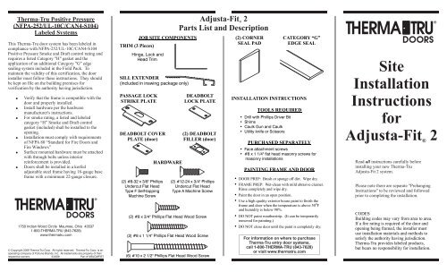
TRIM (3 Pieces)<br />
JOB SITE COMPONENTS<br />
Hinge, Lock and<br />
Head Trim<br />
SILL EXTENDER<br />
(included in inswing package only)<br />
PASSAGE LOCK<br />
STRIKE PLATE<br />
DEADBOLT COVER<br />
PLATE (door)<br />
(2) #8-32 x 3/8" Phillips<br />
Undercut Flat Head<br />
Type F Self-tapping<br />
Machine Screw<br />
HARDWARE<br />
DEADBOLT<br />
LOCK PLATE<br />
(2) DEADBOLT<br />
FILLER (door)<br />
(2) #12-24 x 3/4" Phillips<br />
Undercut Flat Head<br />
Type A Machine Screw<br />
(2) #8 x 3/4" Phillips Flat Head Wood Screw<br />
(2) #8 x 1 1/4" Phillips Flat Head Wood Screw<br />
(6) #10 x 2 1/2" Phillips Flat Head Wood Screw<br />
Adjusta-Fit 2<br />
®<br />
Parts List and Description<br />
(2) CORNER<br />
SEAL PAD<br />
CATEGORY “G”<br />
EDGE SEAL<br />
INSTALLATION INSTRUCTIONS<br />
TOOLS REQUIRED<br />
• Drill with Phillips Driver Bit<br />
• Shims<br />
• Caulk Gun and Caulk<br />
• Utility knife or Scissors<br />
PURCHASED SEPARATELY<br />
• Face attachment screws<br />
• #8 x 1 1/4" flat head masonry screws for<br />
masonry installations<br />
PAINTING FRAME AND DOOR<br />
DOOR PREP: Brush or sponge off dirt. Wipe dry.<br />
<br />
FRAME PREP: Wet-clean with mild abrasive cleaner.<br />
Rinse completely and wipe dry.<br />
<br />
Paint<br />
the door in an open position.<br />
Use a high quality exterior house paint to finish the<br />
O<br />
frame and door when the temperature is above 50 F<br />
and humidity is below 90%.<br />
<br />
DO NOT paint weatherstrip. (It can be temporarily<br />
removed for painting.)<br />
<br />
DO NOT close door until the paint is completely dry.<br />
<br />
For information on where to purchase<br />
<strong>Therma</strong>-<strong>Tru</strong> entry door systems,<br />
call 1-800-THERMA-TRU (843-7628)<br />
or visit www.thermatru.com<br />
Site<br />
Installation<br />
Instructions<br />
for<br />
Adjusta-Fit 2<br />
®<br />
Read all instructions carefully before<br />
installing your new <strong>Therma</strong>-<strong>Tru</strong><br />
Adjusta-Fit 2 system.<br />
Please note there are separate "Prehanging<br />
Instructions" to be reviewed and followed<br />
prior to completing the installation.<br />
CODES<br />
Building codes may vary from area to area.<br />
If a fire rating is required of the door and<br />
opening being framed, the installer must<br />
use installation materials and methods to<br />
satisfy the authority having jurisdiction.<br />
<strong>Therma</strong>-<strong>Tru</strong> provides labeled products,<br />
but bears no responsibility for installation.
1<br />
CHECK ROUGH OPENING SIZE.<br />
Check that door unit<br />
is correct one for<br />
opening.<br />
Check rough opening<br />
width and height for<br />
the appropriate sill<br />
type. See table below.<br />
Rough Opening<br />
Width<br />
If additional carpet clearance<br />
is required, the necessary full<br />
shim under the sill will change<br />
the rough opening height<br />
accordingly.<br />
Rough Opening<br />
Height<br />
Sill Type 6/8 7/0<br />
Inswing 81 1/4" 85 1/4"<br />
Public Access 80 5/8" 84 5/8"<br />
No Sill 80 1/8" 84 1/8"<br />
2<br />
Rough Opening<br />
Height<br />
Floorline<br />
CHECK ROUGH OPENING FOR<br />
ACCURACY.<br />
WARNING: It is critical for<br />
proper fit and operation that<br />
the rough opening is correct<br />
Is subfloor level?<br />
Are walls plumb with jambs?<br />
Are studs or door bucks plumb?<br />
3<br />
UNITS WITH PUBLIC ACCESS<br />
SILLS, CA<strong>UL</strong>K BOTTOM OF SILL<br />
For public access sills, apply caulk along<br />
entire length of sill as shown.<br />
Caulk here<br />
Rough Opening<br />
Width<br />
Door Opening<br />
2/0 25"<br />
2/4 29"<br />
2/6<br />
2/8<br />
2/10<br />
3/0<br />
3/6<br />
31"<br />
33"<br />
35"<br />
37"<br />
43"<br />
4<br />
CENTER UNIT IN OPENING AND<br />
FASTEN FLANGES TO WALL.<br />
Place unit on correct side of opening.<br />
Do not remove “L” bracket until door<br />
is in place, plumb and shimmed.<br />
Center unit in rough opening and set<br />
flanges flush and plumb against wall.<br />
Nail or screw flanges to wall through<br />
punched holes at perimeter.<br />
For jambs exposed to weather: caulk<br />
entire perimeter on underneath side of<br />
nailing flange.<br />
5<br />
LOCATE AND SECURE SHIMS<br />
BETWEEN WALL AND FRAME.<br />
Keeping door closed, carefully shim between wall<br />
and frame. Shim hinge jamb behind hinges and the<br />
lock jamb as indicated in the figure below to plumb<br />
and level the door. Remove “L” bracket from door.<br />
DO NOT allow<br />
shim force to twist<br />
frame. Insufficient<br />
shimming could<br />
cause jamb to bow<br />
at lock area allowing<br />
door to come open<br />
during a fire.<br />
6<br />
Hinge<br />
jamb<br />
shims,<br />
located<br />
behind<br />
hinges.<br />
Lock/<br />
deadbolt<br />
jamb<br />
shims<br />
DRIVE SECURITY SCREWS INTO<br />
HINGE LEAVES.<br />
With door open, at hinges where<br />
indicated, drill 7/64” diameter pilot<br />
holes and fasten #10 x 2 1/2" screws<br />
(provided) through holes in each<br />
hinge leaf.<br />
(6) #10 x 2 1/2"<br />
screws<br />
(Contact your local <strong>Therma</strong>-<strong>Tru</strong> distributor<br />
for alternate screw finishes.)<br />
7<br />
FASTEN LOCK JAMB TO WALL<br />
Close the door and finish securing the face of<br />
the frame in the remaining holes.<br />
Caulk<br />
8<br />
Fasten strike plate with<br />
(2) #12-24 x 3/4" Phillips<br />
flat head Type A machine<br />
screws and deadbolt plate<br />
with (2) #8-32 x 3/8"<br />
Phillips flat head Type F<br />
self-tapping machine<br />
screws provided.<br />
9<br />
10<br />
FASTEN LOCK PLATES TO LOCK<br />
JAMB<br />
CA<strong>UL</strong>K ALONG FRONT OF SILL<br />
BASE.<br />
Prior to installing<br />
extender, apply a<br />
bead of caulk along<br />
front leg of riser.<br />
Caulk<br />
here<br />
INSERT EXTENDER INTO RISER.<br />
Caulk feet of<br />
extender before<br />
sliding into base.<br />
Slide extender<br />
into sill base until<br />
it comes in contact<br />
with jamb stop.<br />
11<br />
Caulk<br />
SLIDE TRIM ONTO JAMBS.<br />
NOTE: If insulation is required between the frame and<br />
rough opening, insulate before sliding trim onto jamb.<br />
Slide hinge and lock trim on<br />
first. Be sure that trim ends are<br />
resting on the sill or floor. Next<br />
apply head trim. Fasten to wall<br />
with nails or screws at hole<br />
locations.<br />
For trim exposed to weather:<br />
caulk entire perimeter on<br />
underneath side of nailing flange.<br />
(refer to step 4 for illustration)<br />
Fasten<br />
Trim<br />
Jamb<br />
12<br />
CA<strong>UL</strong>K UNITS EXPOSED TO<br />
WEATHER.<br />
Apply a bead of<br />
caulk at jamb/sill,<br />
trim/sill, jamb/trim<br />
and sill/floor joints.<br />
Remove paper backing<br />
from self-adhesive<br />
corner seal pads and<br />
apply to jambs with<br />
the wide side pointing<br />
towards the weatherstrip<br />
and bottom edge<br />
resting on the sill.<br />
13<br />
ANCHOR SILL TO FLOOR<br />
Using #8 x 1 1/4" screws,<br />
provided, for wood frame<br />
installation, fasten aluminum<br />
extender to floor thru prepunched<br />
holes.<br />
PAINT<br />
Caulk<br />
When installing into<br />
masonry openings, use<br />
#8 flat head masonry screws following<br />
screw manufacturer's instructions.<br />
14<br />
APPLY CATEGORY "G" EDGE SEAL<br />
Edge Seal<br />
Edge<br />
Seal<br />
Corner<br />
Seal Pad<br />
Caulk<br />
See "PAINTING FRAME AND DOOR" on other side.<br />
15<br />
Cut head edge seal to fit between side<br />
jambs. Apply to head jamb locating<br />
it under and against weatherstrip.<br />
Measure and cut side edge seal to fit<br />
between head and sill. Cut to fit<br />
between hinges and strikes. Locate<br />
and apply to jambs as shown.<br />
#8 x 1 1/4"<br />
screw<br />
(Weatherstrip removed<br />
from illustration for clarity.)