Quad Unit Installation - Therma-Tru Doors
Quad Unit Installation - Therma-Tru Doors
Quad Unit Installation - Therma-Tru Doors

You also want an ePaper? Increase the reach of your titles
YUMPU automatically turns print PDFs into web optimized ePapers that Google loves.
PATIODOORSYSTEMS<br />
®<br />
<strong>Therma</strong>-<strong>Tru</strong><br />
Fiber-Classic<br />
and<br />
Smooth-Star<br />
Sliding Patio<br />
Door System<br />
<strong>Quad</strong> <strong>Unit</strong><br />
Assembly & <strong>Installation</strong><br />
Read all instructions before starting.<br />
The applicable standards for these products are governed by<br />
the International Residential Code.<br />
Copies of performance ratings and testing are available on our website<br />
www.thermatru.com and our product manual.<br />
®<br />
®
1<br />
The following packages are needed to complete the installation of your<br />
Sliding Patio Door System. Check all components for correct size and color.<br />
Frame Kit<br />
1-Head Jamb<br />
2-Side Jambs<br />
1-Sill<br />
2-Active Interlocks<br />
2-Inactive Interlocks<br />
2-Jamb Covers<br />
2-Panel Bumpers<br />
12-#10 x 3" Flat Head Screws<br />
14-#8 x 3" Pan Head Screws<br />
1- This Instruction Booklet<br />
4- Anchor Blocks<br />
4- #10 x 1 1/2" Pan Head Screws<br />
4- #10 x 2 1/2" Pan Head Screws<br />
1-Sill Cap Base<br />
1-Sill Cap Top<br />
1-Drip Cap<br />
1-Head Sealing Fin<br />
2-Corner Pads<br />
2-Foot Bolts<br />
2-Foot Bolt Keepers<br />
2-#8 x 1 1/2" S.S. Pan Head Screw<br />
4-#8 x 1" S.S. Pan Head Screws<br />
1-Touch Up Paint<br />
4-Active Panel Hole Plug<br />
6-#8 x 9/16” Pan Head Screw<br />
Stationary<br />
Panel<br />
Operating<br />
Panel<br />
Operating<br />
Panel<br />
2-Handle Set Kits<br />
2-Handles<br />
1-Exterior Backplate<br />
1-Interior Backplate<br />
2-Keys<br />
2-Handle Screws<br />
3-Phillips Head Machine Screws<br />
1-Allen Wrench<br />
2-Backplate Gaskets<br />
2-Screens (sold separately)<br />
2-Active Panels<br />
2-Inactive Panels<br />
Additional Parts<br />
1-Strike Plate<br />
7-#8 Flat Head Screws<br />
<strong>Therma</strong>-<strong>Tru</strong> ®<br />
Stationary<br />
Panel<br />
Tools and materials needed for<br />
assembly and installation:<br />
100% Silicone Sealant and Caulk Gun<br />
6' Level<br />
Measuring Tape<br />
Electric Drill<br />
#2 Phillips Drive Bit<br />
Staple Gun or Brad Nails<br />
1/8" Drill Bit<br />
Phillips Head Screwdriver<br />
Gloves<br />
Safety Glasses<br />
Partial roll of insulation<br />
Shims<br />
Rubber Mallet
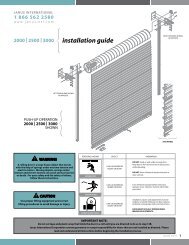
#8 x 3" pan head screw<br />
#10 x 3" flat head screw<br />
SCREW CHART<br />
#8 x 9/16" S.S. pan head screw<br />
#8 x 1" S.S. pan head screw<br />
#8 x 1 1/2" S.S. pan head screw<br />
#10 x 1 1/2" pan head screw<br />
#8 x 2 1/4” flat head screw<br />
#10 x 2 1/2" pan head screw<br />
2
3<br />
1<br />
NOTE:<br />
A large work area is needed to assemble the frame kit. Cover area with<br />
cardboard from one or more door panel cartons to protect frame parts<br />
and floor.<br />
Lay parts on floor and position sill, head,<br />
and side jambs with exterior side up.<br />
Exterior<br />
2<br />
Frame Assembly<br />
LAY FRAME COMPONENTS ONTO WORK AREA<br />
Engage groove in sill cap base with sill.<br />
Rotate sill cap base down to snap into place.<br />
Use a rubber mallet if necessary.<br />
Side Jamb<br />
Sill<br />
Head Jamb<br />
Side Jamb<br />
IF APPLICABLE, INSTALL TOP-HUNG SCREEN<br />
TRACK<br />
For units using the wide profile top-hung screens, install top-hung screen track and<br />
adapter into head jamb prior to assembly.<br />
Reference steps 1 thru 4 of the “Wide Profile” Screen <strong>Installation</strong> - Sliding Patio<br />
instructions, included with the top-hung screen, for complete details.<br />
3<br />
INSTALL SILL CAP BASE<br />
Sill cap base
4<br />
5<br />
ATTACH SILL TO JAMBS<br />
NOTE: Be sure that foam pads are in place before assembling frame.<br />
Apply sealant to sill and side<br />
jambs as shown.<br />
Fasten side jambs to sill through<br />
pre-drilled holes using (3) #10 x 3”<br />
flat head screws. (Starting with<br />
center screw is recommended.)<br />
Repeat of opposite side.<br />
ATTACH HEAD TO JAMBS<br />
Sealant<br />
Sealant<br />
Head Jamb<br />
Jamb<br />
Pads<br />
Apply sealant here<br />
INACTIVE side ONLY<br />
Side Jamb<br />
Sill<br />
Sealant<br />
Jamb<br />
#10 x 3” flat head screw<br />
Apply sealant to end of head<br />
jamb.<br />
Fasten side jambs to head jamb<br />
through pre-drilled holes using<br />
(3) #10 x 3” flat head screws.<br />
(Starting with center screw is<br />
recommended.)<br />
Repeat for opposite side.<br />
#10 x 3” flat head screw<br />
Sill<br />
Sealant<br />
4
DRIP CAP INSTALLATION<br />
Place drip cap on top of head jamb.<br />
Place head sealing fin on top of drip cap, engaging slot in<br />
sealing fin with flange on drip cap.<br />
Staple head sealing fin to each of the anchor blocks in<br />
head jamb using 1/2” staples, nails or screws (not provided).<br />
5<br />
6<br />
7<br />
Head sealing fin<br />
Drip cap<br />
APPLY CORNER PADS TO SEALING FIN<br />
Apply corner pads to<br />
sealing fins at top corners.<br />
Corner pad<br />
Side jamb<br />
Exterior
Check rough opening as follows and correct if necessary:<br />
Sub-floor to be flat, level, and clean. Sill must be supported throughout<br />
its entire length.<br />
All four corners to be square. Check with a framing square.<br />
Framing and walls to be plumb. Use a 6-foot level to check both sides<br />
of opening.<br />
All wall surfaces to be straight and sides parallel.<br />
Opening to be correct size. Allow 3/8" on sides and 1/2" at head.<br />
Wall<br />
straight?<br />
Check each<br />
side both<br />
ways.<br />
Frame <strong>Installation</strong><br />
Check floor<br />
under sill.<br />
Wall<br />
straight?<br />
Check all four<br />
corners with<br />
square.<br />
6
7<br />
8<br />
APPLY SILICONE SEALANT TO SILL AND FINS<br />
Run continuous beads of sealant<br />
across entire length of sill bottom<br />
and around entire perimeter of<br />
backside of sealing fin to<br />
provide a weather-tight seal.<br />
9<br />
Sealant<br />
Sealant<br />
NOTE:<br />
CONTINUOUS BEADS OF<br />
SEALANT ARE REQUIRED.<br />
SET UNIT INTO ROUGH OPENING<br />
From outside of house, set system<br />
into rough opening. Apply pressure<br />
on sill to set sealant.<br />
Exterior
10<br />
LEVEL SILL<br />
Sill MUST be flat and level.<br />
Check and make any necessary adjustments.<br />
If necessary, add temporary blocking under<br />
projecting exterior edge of sill to serve as<br />
support during construction.<br />
11<br />
PLUMB SIDE JAMBS<br />
Jambs must be plumb and straight.<br />
Shim as necessary at screw locations<br />
to remove any bow.<br />
Fasten system to rough opening using<br />
staples, nails, or screws through sealing<br />
fin at the corners.<br />
Fasten through every third opening in<br />
the sealing fin.<br />
If needed, jambs can be back<br />
filled with insulation.<br />
Shims<br />
Interior<br />
8
12<br />
13<br />
9<br />
SECURE FRAME IN ROUGH OPENING<br />
Using (16) #8 x 3" pan head screws, fasten<br />
frame to rough opening through pre-drilled<br />
holes in frame.<br />
#8 x 3" Pan Head Screws<br />
The sill does not have pre-drilled<br />
holes. The screws used on the sill<br />
are installed through the sill cap<br />
base into the sill substrate. There<br />
is a v-groove in the sill cap base<br />
to assist in aligning the screw.<br />
APPLY SEALANT TO INACTIVE DOOR RISERS<br />
Apply a 1/4” continuous bead of clear<br />
sealant along length of both inactive sill<br />
risers at locations shown.<br />
Install these screws three<br />
inches off center in the<br />
direction of the active panel.<br />
Inactive sill riser<br />
Sealant<br />
#8 x 3" Pan Head Screws<br />
Sill Cap Base
14<br />
INSTALL BOTH STATIONARY PANELS<br />
From exterior side of system, install<br />
stationary panel by inserting top of<br />
panel up into exterior channel in head<br />
jamb. Be sure channel is against jamb<br />
and kerfs towards center of unit. See<br />
diagram below.<br />
12<br />
Rotate bottom of panel in until inactive<br />
door riser leg sets into groove.<br />
Slide panel tightly against side jamb<br />
Wipe off excess caulking.<br />
As reference, the exterior side of the<br />
panel is always the pre-finished side.<br />
Repeat for second stationary panel.<br />
15<br />
To center<br />
of unit<br />
INSTALL ANCHOR BLOCKS<br />
Insert anchor blocks into top and<br />
bottom of inactive door panel.<br />
Using a 1/8” drill bit, drill through<br />
angled “toe-screw” hole into head<br />
and sill.<br />
Install #10 x 2 1/2” pan head<br />
screws into “toe-screw” hole.<br />
Fasten anchor block to panel with<br />
#10 x 1 1/2” pan head screws.<br />
Repeat for second stationary panel.<br />
#10 x 2 1/2” pan head screw<br />
#10 x 1 1/2” pan head screw<br />
“toe-screw” hole<br />
Anchor block<br />
Exterior channel<br />
Sill<br />
Sill<br />
Head<br />
Head Jamb<br />
To<br />
jamb<br />
10
16<br />
17<br />
Using a screw driver, turn adjustment<br />
screws in rollers left or right until panel<br />
is level and glides smoothly across the<br />
track.<br />
Close panel to within 1/4" of lock jamb.<br />
Use visual margin to assure panel is<br />
adjusted straight with frame.<br />
11<br />
INSTALL ACTIVE PANELS<br />
From interior side of system, install active<br />
panel up into interior channels in head jamb.<br />
Push upwards as far as possible and rotate<br />
into place until rollers engage sill roller track.<br />
As a reference, the exterior side of the<br />
panel is always the pre-finished side.<br />
Repeat for second active panel.<br />
Interior<br />
Head Jamb<br />
Interior channels<br />
ADJUST ROLLERS<br />
Exterior<br />
To inactive panel To center of unit
18<br />
19<br />
ATTACH INACTIVE INTERLOCKS<br />
Attach inactive interlock to edge of<br />
inactive panel by butting it up into<br />
head jamb and engaging barbs on<br />
interlock with kerfs in door panel.<br />
Use a wood block and hammer or<br />
rubber mallet to tap into place.<br />
Repeat for second inactive panel.<br />
Kerfs<br />
Apply a bead of sealant along<br />
bottom joint of inactive interlock<br />
and sill Sill<br />
INSTALL ACTIVE INTERLOCK<br />
Butt active interlock up against<br />
head jamb leaving a slight gap<br />
of approximately 1/64” between<br />
head jamb and interlock.<br />
Starting at top, insert barbs<br />
into kerfs in door edge.<br />
Working your way down, tap<br />
in place with a hammer and<br />
wood block or rubber mallet.<br />
Carefully inspect interior edge<br />
of interlock. Tap as necessary<br />
to obtain a tight fit along door<br />
edge.<br />
Kerfs<br />
Inactive interlock<br />
Inactive interlock<br />
Inactive interlock<br />
Active interlock<br />
Active interlock<br />
Head jamb<br />
Exterior<br />
Sealant<br />
Slight gap<br />
approx. 1/64”<br />
Active interlock<br />
Head jamb<br />
Active panel<br />
12
20<br />
13<br />
INSTALL CENTER STOP<br />
Measure the door opening and mark at the center point<br />
Center the stop in the door opening at this point<br />
Mark and pre-drill fastening holes in the head jamb<br />
Attach stop to center point of the head jamb<br />
using #10 x 3” flat head screws<br />
D/2<br />
1.104”<br />
D<br />
OPENING WIDTH<br />
Interior<br />
Head Jamb<br />
Center Stop<br />
Bumper<br />
#10 x 3” flat head screw<br />
NOTE:<br />
Do not over torque screw. This<br />
could cause bumper to be dis-formed.<br />
Exterior
21<br />
INSTALL ASTRAGAL<br />
-Line up astragal to the bottom of the panel and predrill<br />
screw holes<br />
-Fit #10 x 1½” pan head screws into astragal at hole<br />
locations<br />
-Place an astragal spacer on the ends of each screw<br />
(shown below)<br />
-Apply the astragal (make sure the slot without<br />
without the weatherstrip is on the interior<br />
side of panel)<br />
Press astragal over panel edge.<br />
-Fasten astragal to panel by tightening the screws<br />
22<br />
Astragal Spacer<br />
INSERT PANEL BUMPERS<br />
Insert panel bumper into first channel<br />
from interior in head jamb, butting<br />
end of bumper against stationary side<br />
jamb. Seat panel bumper flush with<br />
head jamb.<br />
NOTE:<br />
If needed, bumper can be cut<br />
down from its original length<br />
of 6" to 4 ½" . This will allow<br />
for a wider entrance.<br />
Side Jamb<br />
Interior<br />
Exterior<br />
Panel<br />
Bumper<br />
Interior<br />
#10 x 1 1/2” pan head screw<br />
Head Jamb<br />
Panel<br />
Bumper<br />
Panel<br />
Bumper<br />
Exterior<br />
14
23<br />
24<br />
HANDLE INSTALLATION<br />
Refer to instructions supplied with handle set kit.<br />
ATTACH STRIKE PLATE<br />
Align slots in strike plate to<br />
pre-drilled holes in astragal<br />
and fasten with (3) #8 x 2 1/4”<br />
flat head screws.<br />
Close door and adjust strike plate<br />
for proper latch engagement.<br />
Latch throw can be adjusted by<br />
the slotted adjustment screw on<br />
the face of mortise lock.<br />
25<br />
15<br />
Pre-drill (4) 3/32" dia. pilot holes<br />
through each screw hole of the strike<br />
plate into the door panel.<br />
Drive (4) #8 x 2 1/4" flat head screws<br />
through the screw holes of the strike<br />
plate into the door panel as shown.<br />
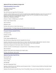
PREP DOOR FOR FOOT BOLT<br />
Tear out template on page 18 to locate and drill holes for foot bolt.<br />
Locate template on interior side of active panel towards inactive panel side.<br />
Align line on template with edge of active door panel and tape into place.<br />
Drill 1/8” dia. x 1” deep holes at hole locations shown on template.<br />
Remove template. Repeat for second active panel.
26<br />
27<br />
28<br />
ATTACH FOOT BOLTS<br />
Align foot bolt to pre-drilled<br />
holes in active slab and fasten<br />
with the supplied S.S. pan head<br />
sheet metal screws included with<br />
the foot bolt.<br />
Repeat for second active panel.<br />
INSTALL SILL CAP TOP<br />
Place a continuous bead of<br />
clear sealant, to locations<br />
shown, along entire length<br />
of sill cap base.<br />
Install sill cap top by<br />
starting at each jamb and<br />
working towards the center<br />
of the door. Use a rubber<br />
mallet to snap into place.<br />
(1) #8 x 1 1/2" S.S. Pan Head<br />
Sheet Metal Screw<br />
Locate on bottom right corner<br />
of the foot bolt.<br />
INSTALL FOOT BOLT KEEPERS<br />
Close the active door completely.<br />
Align notch in keeper with foot bolt<br />
as shown.<br />
Only the two exposed holes will be<br />
used for installation. Pre-drill using<br />
a 1/8" drill bit to drill two holes<br />
through the holes in the keeper into<br />
the sill cap and through the fiberglass<br />
of the sill.<br />
Screw (2) #8 x 1" S.S. Pan head<br />
sheet-metal screws into the holes.<br />
Repeat for second active panel.<br />
Exposed holes<br />
(3) #8 x 9/16"<br />
S.S. Pan Head<br />
Sheet Metal<br />
Screws<br />
Foot bolt<br />
#8 x 1” pan head<br />
screw<br />
Foot bolt keeper<br />
Sill cap top<br />
Sealant<br />
Sill cap base<br />
Notch<br />
16
29<br />
Insert supplied hole plugs<br />
into roller adjustment holes.<br />
30<br />
31<br />
INSERT PLUGS<br />
ATTACH JAMB COVERS<br />
Place jamb covers on inactive<br />
jambs with longer edge pointing<br />
towards inactive panels. Press<br />
into place using a rubber mallet<br />
or a wood block and hammer.<br />
SLIDING SCREEN DOOR<br />
Refer to instructions supplied with screen door.<br />
32<br />
Add insulation to air space between opening and unit.<br />
Caulk around entire perimeter of unit on exterior side; seal sealing fins to<br />
siding or facing, seal front bottom edge of sill, seal all joints between jamb<br />
and mouldings.<br />
Seal joints between exterior hardware trim and door face to prevent air and<br />
water infiltration.<br />
Paint or stain according to <strong>Therma</strong>-<strong>Tru</strong> instructions. Do not paint gaskets or<br />
weatherstrip.<br />
Maintain or replace sealants and finishes as soon as any deterioration is evident.<br />
For semi-gloss or glossy paints or clear coats, do this when surface becomes<br />
dull or rough. More severe exposures require more frequent maintenance.<br />
All <strong>Therma</strong>-<strong>Tru</strong> doors must be finished and maintained in accordance with our<br />
recommendations. Failure to do so may affect the applicable warranty.<br />
Remove sill tape and labels on glass.<br />
Use touch-up paint to paint heads of rough opening screws<br />
17<br />
Inactive panel<br />
Hole plug<br />
Long edge<br />
Jamb cover<br />
Interior<br />
Inactive jamb<br />
WEATHERPROOF, FINISH AND MAINTAIN
FINISHING INSTRUCTIONS<br />
Work only when temperatures are between 50° and 90°F and with humidity less than 85%. Do not finish in direct sunlight.<br />
®<br />
SMOOTH-STAR UNITS<br />
Painting Door Interior:<br />
1. Clean first with mild detergent and water or use a TSP (tri-sodium phosphate) solution.<br />
Rinse well and allow to dry completely.<br />
2. Mask glass and hardware.<br />
3. Use high-quality acrylic latex house paint, following manufacturer's application instructions.<br />
4. Paint edges and exposed ends of door.<br />
®<br />
FIBER-CLASSIC UNITS<br />
Painting Door Interior:<br />
1. Clean first with mild detergent and water or use a TSP (tri-sodium phosphate) solution.<br />
Rinse well and allow to dry completely.<br />
2. Mask glass and hardware.<br />
3. Prime with an alkyd- or acrylic-based primer. Allow primer to dry completely.<br />
4. Paint with an oil-based or acrylic latex house paint, following manufacturer’s application instructions. Use a primer<br />
and paint that are compatible.<br />
5. Paint edges and exposed ends of door.<br />
Staining Door Interior:<br />
We only recommend the use of the stain and clear coat products found in the <strong>Therma</strong>-<strong>Tru</strong><br />
Finishing System. (See the <strong>Therma</strong>-<strong>Tru</strong> Finishing System instructions for complete details.)<br />
1. Clean first with a clean cloth and mineral spirits and allow to air dry OR wash door with a mild detergent and water, or a TSP<br />
(tri-sodium phosphate) solution. Rinse well and allow to dry completely.<br />
2. Mask glass and hardware.<br />
3. Apply stain with a cloth in a circular motion to one section at a time.<br />
4. Wait 5-10 minutes before brushing, depending on the desire for a lighter or darker shade.<br />
5. Brush with the natural bristle brush in the direction of the grain to “feather” or blend the stain to a rich wood look.<br />
Clean brush tips frequently with a dry cloth to remove excess stain. Stain<br />
moving onto next section.<br />
and brush out each section completely before<br />
6. Allow a minimum of 48 hours drying time for the stain to cure before applying topcoat.<br />
REPAINTING PROCEDURE<br />
1. Sand the surface to be re-coated with 180 grit sandpaper to abrade and make porous.<br />
2. Remove all sanding dust from the surface. This can be accomplished by using a damp cloth.<br />
3. Optional: Wipe the surface with a solvent paint deglosser applied with a clean cloth followed<br />
by a final wipe with an additional clean cloth to ensure the surface is free of any contaminates.<br />
TM<br />
4. Apply Sherwin Williams DTM Bonding Primer part # B66A50 to the surface and let the<br />
coating dry, following the directions provided on the label located on the back of the can.<br />
TM<br />
5. Topcoat the Sherwin Williams DTM Bonding Primer with a high quality acrylic latex<br />
coating such as Sherwin Williams SuperPaint A84 Series or Sherwin Williams DTM<br />
Acrylic Coating B66 Series.<br />
For store locations of the above mentioned paints call 1-800-4SHERWIN<br />
TM<br />
Corresponding Sherwin Williams SuperPaint Codes:<br />
TM TM<br />
BRONZE WHITE STONE ALMOND<br />
A89T54 A89W507 A89W53 A89W51<br />
N1 10/32 R2 1/128 B1 9/32 B1 4/32 +1/64<br />
R2 13/32 B1 1/64 W1 10/32 Y3 19/32<br />
W1 39/32<br />
B1 6Y +62/32<br />
N1 1/64 N1 2Y +46/32 N1 2Y +18/32<br />
18
19<br />
Towards<br />
inactive<br />
panel<br />
Active panel edge<br />
Bottom door edge<br />
1/8” dia holes<br />
1” deep<br />
Bottom corner<br />
of active panel<br />
Towards<br />
inactive<br />
panel
21<br />
JAMB EXTENSION INFORMATION<br />
The following images are intended to help clarify how a patio door is<br />
installed in different frame openings.<br />
The jamb extensions are made of standard wood trim materials, readily<br />
available from lumber yards and building material retail stores.<br />
Attach the jamb extensions through the side into the wall.<br />
Exterior<br />
2 x 4 CONSTRUCTION<br />
1 1/8”<br />
4 9/16"<br />
2”<br />
Exterior<br />
3/4"<br />
2 x 6 CONSTRUCTION<br />
1 1/8"<br />
6 9/16"
INTERIOR CASING ATTACHMENT<br />
Interior casing may be attached to the frame in either of the following ways:<br />
An air nailer can be used to fasten the interior casing to the frame using 0.050" x<br />
1-1/2" wire brad nails through the casing and fiberglass frame. For maximum<br />
holding power, ensure that nails are installed through anchor blocks located within<br />
frame profiles. Locations are shown below.<br />
For manual application, we suggest using 4d-1-1/2" finish nails. They can be used<br />
to secure interior casing to the frame. Pre-drilled pilot holes (1/16" dia.) are<br />
recommended to avoid splitting casing or frame. Ensure that nails are installed<br />
through anchor blocks for maximum holding power.<br />
6 1/4”<br />
10/0 = 60”<br />
12/0 = 72”<br />
6 1/4”<br />
1” 1”<br />
5” 5”<br />
31” 31”<br />
5” 5”<br />
22
23<br />
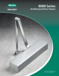
SIZING INFORMATION<br />
<strong>Therma</strong>-<strong>Tru</strong> Fiber-Classic/Smooth-Star Sliding Patio Specifications<br />
Description Configuration<br />
<strong>Unit</strong> Size<br />
Width Height<br />
Rough Opening<br />
Width Height<br />
Grids<br />
# of Lites<br />
10/0 x R.H. OXXO 115 3/4 79 1/2 116 1/2 80 10 or 15<br />
12/0 x R.H. OXXO 139 3/4 79 1/2 140 1/2 80 10 or 15<br />
10/0 x F.H.<br />
12/0 x F.H.<br />
10/0 x 8/0<br />
12/0 x 8/0<br />
R.H. Replacement Height<br />
F.H. Full Height<br />
8/0 8’ Height<br />
X Active Door<br />
O Inactive Door<br />
Door Width<br />
Daylight<br />
Width<br />
Daylight<br />
Height<br />
OXXO<br />
OXXO<br />
OXXO<br />
OXXO<br />
<strong>Unit</strong> Height<br />
115 3/4<br />
139 3/4<br />
115 3/4<br />
139 3/4<br />
Door Height<br />
82<br />
82<br />
95 1/2<br />
95 1/2<br />
116 1/2<br />
140 1/2<br />
116 1/2<br />
140 1/2<br />
82 1/2<br />
82 1/2<br />
96<br />
96<br />
<strong>Unit</strong> Width<br />
10 or 15<br />
10 or 15<br />
12 or 18<br />
12 or 18<br />
Door Panel Information<br />
Fiber-Classic<br />
Door Size Daylight Opening<br />
Width Height Width Height<br />
2/6 x R.H. 29 1/2 76 3/16 20 63 1/8<br />
2/6 x F.H. 29 1/2 78 11/16 20 63 1/8<br />
2/6 x 8/0 29 1/2 92 3/16 19 13/16 78 13/16<br />
3/0 x R.H. 35 1/2 76 3/16 26 63 1/8<br />
3/0 x F.H. 35 1/2 78 11/16 26 63 1/8<br />
3/0 x 8/0 35 1/2 92 3/16 23 13/16 78 13/16<br />
Smooth-Star<br />
Door Size Daylight Opening<br />
Width Height Width Height<br />
2/6 x R.H. 29 9/16 76 3/16 20 63 1/8<br />
2/6 x F.H. 29 9/16 78 11/16 20 63 1/8<br />
2/6 x 8/0 29 9/16 92 3/16 19 13/16 78 13/16<br />
3/0 x R.H. 35 9/16 76 3/16 24 1/8 63 1/8<br />
3/0 x F.H. 35 9/16 78 11/16 24 1/8 63 1/8<br />
3/0 x 8/0 35 9/16 92 3/16 23 13/16 78 13/16
PATIODOORSYSTEMS<br />
1687 Woodlands Dr. Maumee, OH 43537<br />
1-800-THERMATRU (843-7628)<br />
www.thermatru.com<br />
© 2005 <strong>Therma</strong>-<strong>Tru</strong> Corp.<br />
<strong>Therma</strong>-<strong>Tru</strong> <strong>Doors</strong> is an operating company of Fortune Brands, Inc. Part # FCSSSPQAD<br />
09/12/05