The case of the hidden harmonic filter - lighting - ETC
The case of the hidden harmonic filter - lighting - ETC
The case of the hidden harmonic filter - lighting - ETC

Create successful ePaper yourself
Turn your PDF publications into a flip-book with our unique Google optimized e-Paper software.
SPRING 2008<br />
<strong>The</strong> <strong>case</strong> <strong>of</strong> <strong>the</strong><br />
<strong>hidden</strong> <strong>harmonic</strong> <strong>filter</strong><br />
Fur<strong>the</strong>r adventures <strong>of</strong> <strong>the</strong> power quality detectives<br />
I receNtlY Wrote ABout NeW tools for <strong>harmonic</strong><br />
management and power quality (“New tools <strong>of</strong>fer Power Quality<br />
and efficiency” in <strong>the</strong> Fall 2007 issue <strong>of</strong> Protocol). In that article,<br />
<strong>harmonic</strong> Blocking Filters and <strong>the</strong>ir incompatibility with phasecontrol<br />
dimming systems were explained. coincidentally, just as <strong>the</strong><br />
article was published, we received a call from one <strong>of</strong> our dealers,<br />
PrG, with a problematic installation <strong>of</strong> a new dimming system. <strong>the</strong><br />
failure was quite simple in its description: when large numbers <strong>of</strong><br />
dimmers were set to levels below full, <strong>the</strong> entire system flickered<br />
and flashed, and horrible noises came from <strong>the</strong> dimmer rack and<br />
feeders. Phase and neutral connections appeared to be torqued<br />
to specifications, and <strong>the</strong> system worked fine as long as a small<br />
number <strong>of</strong> dimmers were energized, or all dimmers were set to full.<br />
<strong>the</strong> system neutral conductor (<strong>of</strong>ten a culprit in this sort <strong>of</strong> flickerand-flash<br />
failure) was sized correctly. Voltages to <strong>the</strong> dimmer rack<br />
appeared to be normal. We had a first class mystery on our hands.<br />
In discussions with rob tooker, PrG Project Manager, a<br />
small but important clue emerged on an equipment label: <strong>the</strong><br />
manufacturer <strong>of</strong> <strong>the</strong> transformer feeding <strong>the</strong> dimming system was<br />
Harmonics Limited. this immediately got my warning bells ringing,<br />
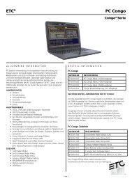
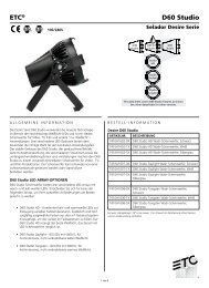
figure 1--Typical Installation <strong>of</strong> <strong>harmonic</strong> Blocking <strong>filter</strong><br />
20<br />
SprING 2008<br />
bY STEVE TERRy<br />
since standard transformer manufacturers do not generally have <strong>the</strong><br />
word <strong>harmonic</strong>s in <strong>the</strong>ir names. could <strong>the</strong>re be something <strong>hidden</strong><br />
in this transformer that was causing <strong>the</strong> problem?<br />
<strong>the</strong> symptoms <strong>of</strong> <strong>the</strong> failure mimicked those produced by a<br />
third <strong>harmonic</strong> blocking <strong>filter</strong>, even though <strong>the</strong>re was no <strong>filter</strong><br />
in evidence. Pulling my sherlock holmes hat out <strong>of</strong> <strong>the</strong> closet, I<br />
conducted a thorough search <strong>of</strong> <strong>the</strong> transformer manufacturer’s<br />
website. this revealed that <strong>the</strong>y make transformer enclosures with<br />
built-in third <strong>harmonic</strong> blocking <strong>filter</strong>s connected in series with <strong>the</strong><br />
neutral conductor (see Figure 1). Aha, <strong>the</strong> smoking gun revealed!<br />
Based on past experience, <strong>the</strong> presence <strong>of</strong> such a device might<br />
be <strong>the</strong> likely cause <strong>of</strong> <strong>the</strong> problem. And now, this <strong>case</strong> presented<br />
a unique and interesting opportunity: we had a system that was<br />
likely failing due to an incompatible piece <strong>of</strong> <strong>harmonic</strong> mitigation<br />
equipment (<strong>hidden</strong> from view, so far!), and we had “<strong>the</strong> suspect in<br />
<strong>the</strong> holding cell” so that we could precisely observe and analyze <strong>the</strong><br />
reasons for <strong>the</strong> failure.<br />
As such, I asked rob tooker (who was responsible for all <strong>the</strong><br />
fieldwork in this detective story) to go back to <strong>the</strong> site armed with<br />
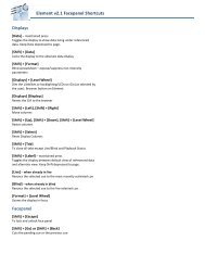
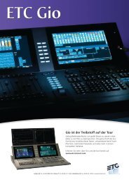
PrG’s Dranetz 4300 power quality analysis system. this type <strong>of</strong><br />
device is invaluable for analyzing power<br />
issues <strong>of</strong> all kinds. It typically has 4 channels<br />
<strong>of</strong> voltage measurement (A, B, c phases<br />
plus neutral-to ground) and four channels<br />
<strong>of</strong> current measurement (A, B, c phases,<br />
and neutral).It contains s<strong>of</strong>tware to create<br />
a real-time plot <strong>of</strong> what is happening in <strong>the</strong><br />
system, as well as Fast Fourier transform<br />
(FFt) analysis to determine <strong>the</strong> <strong>harmonic</strong><br />
content <strong>of</strong> voltage and current waveforms.<br />
It is useful for monitoring spurious power<br />
line events that only occur intermittently,<br />
because it can be programmed to take a
Figure 2<br />
measurement snapshot whenever a predetermined set <strong>of</strong> thresholds<br />
is crossed. For instance, one can say: “Show me everything that<br />
happens in current and voltage when <strong>the</strong> A, B, or C phases fall<br />
below 105 volts.” Or, “Give me a <strong>harmonic</strong> analysis whenever<br />
<strong>the</strong> total <strong>harmonic</strong> distortion in voltage exceeds 5% <strong>of</strong> <strong>the</strong><br />
fundamental.” It is truly a scene-<strong>of</strong>-<strong>the</strong>-crime tool that lays bare any<br />
21<br />
protocol<br />
and all power line events for careful analysis<br />
and failure mitigation. Figure 2 shows <strong>the</strong><br />
system connected at <strong>the</strong> problem site.<br />
On this project, however, <strong>the</strong> advanced<br />
threshold features <strong>of</strong> <strong>the</strong> analyzer would<br />
not be needed. Rob simply got <strong>the</strong> dimming<br />
system into a failure mode by setting lots<br />
<strong>of</strong> dimmers at about 50%, and <strong>the</strong>n took<br />
snapshots with <strong>the</strong> analyzer. <strong>The</strong> results are<br />
fascinating evidence <strong>of</strong> <strong>the</strong> behavior <strong>of</strong> a<br />
<strong>harmonic</strong> blocking <strong>filter</strong> that is connected<br />
to a phase-control dimming system, and<br />
present clear reasons why one should never<br />
do that. As background, let’s review how a<br />
third <strong>harmonic</strong> blocking <strong>filter</strong> works.<br />
A <strong>harmonic</strong> blocking <strong>filter</strong> (or Harmonic<br />
Suppression System) places an R-L-C<br />
(resistive-inductive-capacitive) tuned <strong>filter</strong><br />
in series with <strong>the</strong> system neutral connection.<br />
This <strong>filter</strong> presents very high impedance to<br />
third <strong>harmonic</strong> currents <strong>of</strong> 180 Hz (three<br />
times <strong>the</strong> 60Hz fundamental frequency), and does not allow <strong>the</strong>m<br />
to pass. <strong>The</strong> result, however, is very high third <strong>harmonic</strong> voltage<br />
distortion. <strong>The</strong>se <strong>filter</strong>s were originally designed to feed <strong>of</strong>fice<br />
equipment that uses switch-mode power supplies that do not mind<br />
high third <strong>harmonic</strong> voltage distortion, but <strong>the</strong>y are fundamentally<br />
incompatible with phase-control dimmers.<br />
SPRING 2008
SPRING 2008<br />
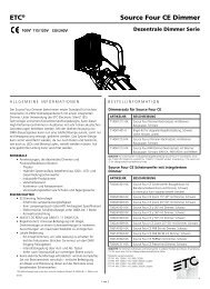
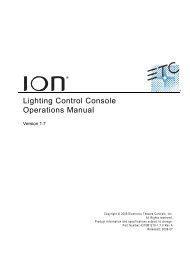
figure 3--a Phase Voltage & Current--With <strong>filter</strong><br />
A<br />
C<br />
B<br />
figure 4--a Phase Voltage Distortion--With <strong>filter</strong><br />
figure 5--a Phase Current--With <strong>filter</strong><br />
D<br />
22<br />
SprING 2008<br />
Version 2.05<br />
Version 2.05<br />
that incompatibility is precisely what<br />
happened at our site, as <strong>the</strong> analysis data<br />
shows. refer to Figure 3, which shows <strong>the</strong><br />
voltage and current waveforms for <strong>the</strong><br />
A phase when <strong>the</strong> dimming system is set<br />
with all dimmers at 50%. <strong>the</strong> black trace<br />
is current and blue is voltage. At callout A,<br />
you can see all <strong>the</strong> A-phase dimmers turn<br />
on and current begin to flow. At this point,<br />
<strong>the</strong> majority <strong>of</strong> <strong>the</strong> current is in <strong>the</strong> third<br />
<strong>harmonic</strong> (normal for a phase-control<br />
dimmer), which is where <strong>the</strong> tuned<strong>filter</strong><br />
presents a high impedance. Almost<br />
immediately, at callout B, you can see <strong>the</strong><br />
blue voltage waveform collapse as <strong>the</strong> third<br />
<strong>harmonic</strong> current is choked <strong>of</strong>f by <strong>the</strong><br />
<strong>filter</strong>. <strong>the</strong> voltage collapse is so severe that<br />
<strong>the</strong> voltage waveform experiences a false<br />
zero-crossing at callout c. At callout D,<br />
<strong>the</strong> <strong>filter</strong> recovers and both <strong>the</strong> voltage and<br />
current begin to rise. <strong>of</strong> course, that does<br />
not matter much, since our phase-control<br />
dimming system is failing miserably due<br />
to <strong>the</strong> extra zero crossing and voltage<br />
fluctuations that are far outside its ability<br />
to regulate.<br />
Now take a look at Figure 4, which is a<br />
FFt (Fast Fourier transform) analysis <strong>of</strong><br />
<strong>the</strong> voltage waveform in Figure 3. <strong>the</strong>re<br />
is tremendous third <strong>harmonic</strong> voltage<br />
distortion, about 55% <strong>of</strong> <strong>the</strong> fundamental.<br />
And this has exactly <strong>the</strong> effect that <strong>the</strong> <strong>filter</strong><br />
manufacturer wants, as shown in Figure 5,<br />
a FFt analysis <strong>of</strong> <strong>the</strong> current in Figure 3.<br />
You can see that <strong>the</strong> third <strong>harmonic</strong> current<br />
has been reduced to just over 10% <strong>of</strong> <strong>the</strong><br />
fundamental current (see typical third<br />
<strong>harmonic</strong> current in Figure 9 for what<br />
we would expect in a normally operating<br />
phase control dimming system). But wait,<br />
what’s happening here in Figure 5? <strong>the</strong><br />
fifth and seventh <strong>harmonic</strong> currents are now<br />
nearly 50% and 25% <strong>of</strong> <strong>the</strong> fundamental,<br />
respectively! Interesting, since phase-control<br />
dimmers do not generate fifth and seventh<br />
<strong>harmonic</strong>s! oh yes <strong>the</strong>y do, when presented<br />
with a voltage waveform that is so grossly<br />
distorted and rich in third <strong>harmonic</strong> as<br />
<strong>the</strong> one in Figure 3. But this presence <strong>of</strong><br />
fifth and seventh <strong>harmonic</strong> current is only
academically interesting, since <strong>the</strong> dimming<br />
system is failing miserably under <strong>the</strong>se<br />
conditions.<br />
since our <strong>harmonic</strong> blocking <strong>filter</strong> is a<br />
high impedance in series with <strong>the</strong> neutral<br />
(look back at Figure 1), which is common<br />
to all three phases, it also causes interaction<br />
artifacts between <strong>the</strong> three phases. For a<br />
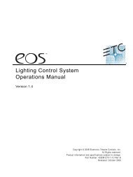
good view <strong>of</strong> this, take a look at Figure 6,<br />
a picture <strong>of</strong> <strong>the</strong> voltage waveforms on all<br />
three phases. <strong>the</strong>se waveforms bear little<br />
resemblance to sine waves.<br />
having conclusively determined that<br />
<strong>the</strong> <strong>harmonic</strong> blocking <strong>filter</strong> <strong>hidden</strong> in<br />
our transformer enclosure was <strong>the</strong> culprit,<br />
we asked <strong>the</strong> owner to determine if <strong>the</strong><br />
<strong>filter</strong> could be removed without removing<br />
<strong>the</strong> transformer itself. It could indeed be<br />
removed, and when it was, <strong>the</strong> system<br />
magically began functioning normally!<br />
triumph <strong>of</strong> <strong>the</strong> Power Quality Detectives!<br />
rob <strong>the</strong>n went back to <strong>the</strong> site to ga<strong>the</strong>r<br />
before and after data. take a look at<br />
Figure 7 for <strong>the</strong> A Phase voltage and<br />
current waveforms under approximately <strong>the</strong><br />
same conditions as those <strong>of</strong> Figure 3, but<br />
without <strong>the</strong> culprit <strong>filter</strong> in line. At callout<br />
e, <strong>the</strong> dimmers turn on at about 50% and<br />
<strong>the</strong> current begins to flow. But instead <strong>of</strong><br />
causing <strong>the</strong> complete collapse <strong>of</strong> <strong>the</strong> voltage<br />
waveform that we saw in Figure 3, <strong>the</strong> result<br />
<strong>of</strong> this dimmer turn-on is merely a small<br />
notch in <strong>the</strong> voltage waveform at callout F.<br />
Figure 8 shows us <strong>the</strong> FFt analysis<br />
<strong>of</strong> <strong>the</strong> voltage with <strong>the</strong> <strong>filter</strong> removed.<br />
Note that <strong>the</strong>re is some third <strong>harmonic</strong><br />
distortion caused by <strong>the</strong> notching, but <strong>the</strong><br />
total <strong>harmonic</strong> Distortion in voltage is less<br />
than 5% <strong>of</strong> <strong>the</strong> fundamental, well within<br />
<strong>the</strong> limits set by Ieee 519-2 Recommended<br />
Practices and Requirements for Harmonic<br />
Control in Electrical Power Systems. Now<br />
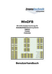
take a look at Figure 9, <strong>the</strong> FFt analysis <strong>of</strong><br />
<strong>the</strong> current being drawn by <strong>the</strong> dimming<br />
system with <strong>the</strong> <strong>filter</strong> removed. You can see<br />
large amounts <strong>of</strong> third <strong>harmonic</strong>, and <strong>the</strong><br />
total <strong>harmonic</strong> Distortion in current is<br />
43% <strong>of</strong> <strong>the</strong> fundamental. this sounds like<br />
a large number, but because <strong>the</strong> electrical<br />
system is now properly designed to handle<br />
F<br />
23<br />
proToCoL<br />
figure 6--a, B, C Phase Voltage--With <strong>filter</strong><br />
figure 7--a Phase Voltage & Current--<strong>filter</strong> removed<br />
E<br />
figure 8--a Phase Voltage Distortion--<strong>filter</strong> removed<br />
Version 2.05<br />
SPRING 2008
SPRING 2008<br />
C<br />
M<br />
Y<br />
CM<br />
MY<br />
CY<br />
CMY<br />
K<br />
protoical_ad-org.ai 2/28/2008 9:18:56 AM<br />
BA R BIZON LIGHTING COMPA N Y<br />
Lighting Products and Equipment for <strong>The</strong>atre,<br />
Television, Film and <strong>The</strong>med Environments<br />
Systems Integration and Technical Services<br />
Rigging Systems<br />
www.barbizon.com<br />
866-502-2724<br />
figure Figure 9-a 9-A Phase Current--<strong>filter</strong> Current—Filter Removed<br />
removed<br />
Atlanta • Boston • Charlotte • Chicago • Dallas • Denver • London<br />
Miami • New York • Orlando • Phoenix • Washington, D.C.<br />
24<br />
SprING 2008<br />
it, <strong>the</strong> large <strong>harmonic</strong> currents, which are<br />
a fact <strong>of</strong> life with phase-control dimming<br />
systems, are having almost no effect on <strong>the</strong><br />
quality <strong>of</strong> <strong>the</strong> voltage supplied to <strong>the</strong> system.<br />
<strong>the</strong>re are many methods <strong>of</strong> dealing with<br />
<strong>harmonic</strong>s (see <strong>the</strong> <strong>harmonic</strong> Mitigation<br />
toolbox on page 25). this mystery shows<br />
in great detail why <strong>the</strong> third option, “Accept<br />
<strong>harmonic</strong> currents” method is <strong>the</strong> weapon<br />
<strong>of</strong> choice when dealing with phase-control<br />
dimming systems. equally important is that<br />
not all <strong>harmonic</strong> mitigation methods work<br />
well for all types <strong>of</strong> equipment, a point that<br />
was graphically proved with our culprit<br />
<strong>harmonic</strong> blocking <strong>filter</strong>. ■<br />
Steve Terry is <strong>the</strong><br />
Vp <strong>of</strong> research &<br />
Development at <strong>ETC</strong>,<br />
and a sometime<br />
power Quality<br />
Detective. He is<br />
<strong>the</strong> alternate USITT<br />
representative on<br />
National Electrical<br />
Code panel 15, and a<br />
member <strong>of</strong> <strong>the</strong> ESTA<br />
Board <strong>of</strong> Directors.
<strong>The</strong> Harmonic mitigation Toolbox<br />
<strong>The</strong>re are many, many paths to <strong>harmonic</strong><br />
mitigation in power systems, but <strong>the</strong> common<br />
ones fall into three basic categories:<br />
1. Suppress <strong>the</strong> objectionable <strong>harmonic</strong> current. This is <strong>the</strong><br />
approach <strong>of</strong> <strong>the</strong> passive <strong>harmonic</strong> blocking <strong>filter</strong>.<br />
Pros<br />
• Inexpensive <strong>harmonic</strong> mitigation solution<br />
• useful for local <strong>harmonic</strong> mitigation <strong>of</strong> specific type <strong>of</strong> loads<br />
such as PC’s and <strong>of</strong>fice equipment<br />
Cons<br />
• Produces large voltage distortion as a byproduct <strong>of</strong> suppressing<br />
<strong>harmonic</strong> currents. This voltage distortion may adversely<br />
affect equipment o<strong>the</strong>r than PC’s and <strong>of</strong>fice equipment that<br />
use switch-mode power supplies. Such voltage distortion<br />
may not comply with Ieee 519-2 Recommended Practices<br />
and Requirements for Harmonic Control in Electrical Power<br />
Systems.<br />
• Incompatible with some types <strong>of</strong> equipment like phase-control<br />
dimmers, <strong>the</strong> mainstay <strong>of</strong> <strong>the</strong> entertainment industry. This<br />
requires policing <strong>of</strong> connected loads to maintain compatibility.<br />
• As an artifact, may produce different <strong>harmonic</strong> currents than<br />
<strong>the</strong> mitigation target <strong>of</strong> <strong>the</strong> <strong>filter</strong>. <strong>The</strong>se may require yet<br />
ano<strong>the</strong>r, additional mitigation approach.<br />
2. Inject current into <strong>the</strong> system using an intelligent adaptive<br />
<strong>filter</strong> or active <strong>filter</strong>. <strong>The</strong>se devices contain analysis hardware<br />
and s<strong>of</strong>tware that characterizes <strong>the</strong> non-sinusoidal current<br />
waveform <strong>of</strong> <strong>the</strong> <strong>harmonic</strong>-producing equipment, and <strong>the</strong>n<br />
injects current into <strong>the</strong> feeder in a complementary waveform<br />
to make <strong>the</strong> final current waveform into a pure sine wave.<br />
Pros<br />
• A properly designed and specified adaptive <strong>filter</strong> will<br />
eliminate objectionable <strong>harmonic</strong> currents without<br />
negative byproducts.<br />
Cons<br />
• breathtakingly expensive—especially at <strong>the</strong> high power levels<br />
typical <strong>of</strong> entertainment dimming systems<br />
• Physically large and complex—subject to a shorter mean<br />
time between failures than passive devices<br />
• major components such as capacitors (<strong>the</strong> items that store <strong>the</strong><br />
current injected into <strong>the</strong> feeder) have a finite life and require<br />
regular replacement.<br />
• may be incompatible with certain types <strong>of</strong> equipment—<br />
<strong>the</strong>re is no industry experience with phase- controlled dimmers<br />
3. accept <strong>the</strong> <strong>harmonic</strong> currents from certain types <strong>of</strong> electrical<br />
equipment (like phase-control dimmers) and design <strong>the</strong> rest<br />
<strong>of</strong> <strong>the</strong> electrical system to prevent propagation <strong>of</strong> damaging<br />
25<br />
proToCoL<br />
voltage distortion. This approach relies on proper transformer<br />
selection (Harmonic mitigating or K-rated) and upsizing <strong>of</strong><br />
neutral conductors where required.<br />
Pros<br />
• relatively inexpensive<br />
• Completely compatible with phase-control dimming systems—<br />
this makes it <strong>the</strong> choice <strong>of</strong> <strong>the</strong> entertainment industry<br />
• especially applicable to <strong>the</strong> triplen <strong>harmonic</strong>s produced by<br />
phase-control dimming systems, since <strong>the</strong>se are blocked at <strong>the</strong><br />
delta-wye transformer—<strong>the</strong> primary tool <strong>of</strong> this approach.<br />
• Does not require policing <strong>of</strong> connected loads to insure<br />
compatibility with mitigation method<br />
• New, efficient solutions like Harmonic mitigating Transformers<br />
(HmT’s) can now do a greener job on this approach than<br />
popular K-rated transformers previously used<br />
• Very simple and reliable<br />
• Insures compliance with Ieee 519-2<br />
Cons<br />
• requires delta-wye HmT’s or K-rated transformers between <strong>the</strong><br />
<strong>harmonic</strong> producing device (a phase-control dimming system,<br />
for example) and <strong>the</strong> rest <strong>of</strong> <strong>the</strong> facility.<br />
<strong>The</strong>re will be floods.<br />
<strong>The</strong>re will be grids.<br />
<strong>The</strong>re will be stars.<br />
And when your ambition meets <strong>the</strong><br />
deadline, you can get help from LVH<br />
for whatever you need to get on with <strong>the</strong><br />
show. LVH specializes in rigging, <strong>lighting</strong><br />
and drapery installations as well as<br />
<strong>the</strong> myriad <strong>of</strong> devices and<br />
services it takes to support any venue.<br />
Not to mention safety surveys to make<br />
sure everything works <strong>the</strong> way you want<br />
it to. Give LVH a call.<br />
SPRING 2008