Study on Vibratory Feeders: Calculation of Natural Freq uency of ...
Study on Vibratory Feeders: Calculation of Natural Freq uency of ...
Study on Vibratory Feeders: Calculation of Natural Freq uency of ...

You also want an ePaper? Increase the reach of your titles
YUMPU automatically turns print PDFs into web optimized ePapers that Google loves.
CENTER LINE OF<br />
LEAF SPRING<br />
r^^yjy/^//////^<br />
(a)<br />
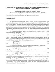
Fig. 2 Deflecti<strong>on</strong> <strong>of</strong> leaf spring in bowl-type vibratory feeder<br />
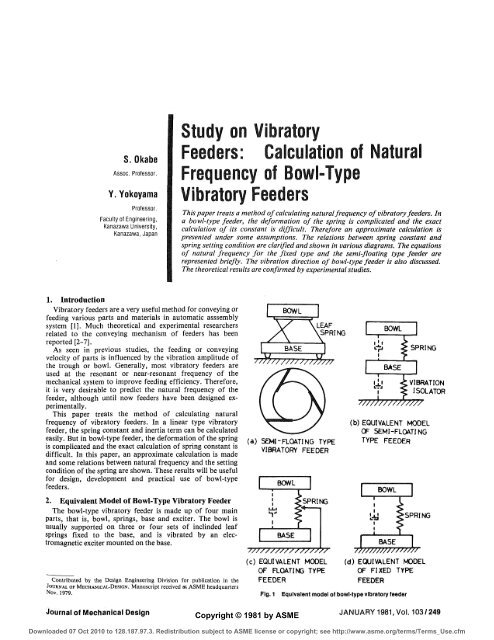
The vibratory feeder is <strong>of</strong>ten mounted <strong>on</strong> vibrati<strong>on</strong><br />
isolators, for example rubber feet, as shown schematically in<br />
Fig. 1(a), (b), to minimize the force transmissi<strong>on</strong> to the<br />
foundati<strong>on</strong>. The relati<strong>on</strong>s between mounting c<strong>on</strong>diti<strong>on</strong>s and<br />
dynamic characteristics <strong>of</strong> the feeder have already been<br />
clarified [8]. According to this previous study, if the stiffness<br />
<strong>of</strong> the vibrati<strong>on</strong> isolator is less than about <strong>on</strong>e-fifth <strong>of</strong> that <strong>of</strong><br />
the lead spring, the vibratory characteristics can be approximated<br />
by those <strong>of</strong> a floating type feeder which is supported<br />
at the nodal point <strong>of</strong> spring, as shown in Fig. 1(c).<br />
If the feeder is mounted <strong>on</strong> a foundati<strong>on</strong> without a<br />
vibrati<strong>on</strong> isolator, the equivalent model <strong>of</strong> the feeder is<br />
presented in Fig. 1(d).<br />
3. Deformati<strong>on</strong> <strong>of</strong> Leaf Spring and Some Assumpti<strong>on</strong>s<br />
for Analyses<br />
In a bowl-type feeder, three or four sets <strong>of</strong> inclined leaf<br />
springs are arranged al<strong>on</strong>g a circumference. Then the<br />
movement <strong>of</strong> the bowl has an angular vibrati<strong>on</strong> about its<br />
vertical axis together with a vertical vibrati<strong>on</strong>.<br />
Nomenclature<br />
b = width <strong>of</strong> leaf spring<br />
E = Young's modulus<br />
/nl = natural freq<strong>uency</strong> <strong>of</strong> fixed type vibratory feeder<br />
/„2 = natural freq<strong>uency</strong> <strong>of</strong> floating and semi-floating<br />
type vibratory feeder<br />
G = shear modulus<br />
h = thickness <strong>of</strong> leaf spring<br />
/;. = geometrical moment <strong>of</strong> inertia<br />
J = inertia moment about vertical axis <strong>of</strong> bowl<br />
ke = equivalent spring c<strong>on</strong>stant<br />
ki = numerical factor<br />
K.E. = kinetic energy <strong>of</strong> bowl<br />
/ = length <strong>of</strong> leaf spring<br />
M = mass <strong>of</strong> bowl<br />
Me = equivalent inertia mass<br />
Ms = bending moment at end <strong>of</strong> spring (in width<br />
directi<strong>on</strong>)<br />
M, = torsi<strong>on</strong>al moment<br />
n = number <strong>of</strong> leaf springs<br />
Rs = shearing force at end <strong>of</strong> spring (in width directi<strong>on</strong>)<br />
(b)<br />
B<br />
'B'<br />
5:<br />
6r<br />
0<br />
CENTER LINE OF<br />
LEAF SPRING<br />
AC'<br />
B'C<br />
^C'AB'<br />
In this case, the deformati<strong>on</strong> <strong>of</strong> each spring is very complicated.<br />
Therefore, in order to simplify the discussi<strong>on</strong>, the<br />
following assumpti<strong>on</strong>s are presented:<br />
The deformati<strong>on</strong> <strong>of</strong> the leaf spring is influenced by the<br />
deformati<strong>on</strong>s in (i) thickness directi<strong>on</strong>, (ii) width directi<strong>on</strong><br />
and (Hi) torsi<strong>on</strong>. These deformati<strong>on</strong>s are independent <strong>of</strong> <strong>on</strong>e<br />
another without any geometrical c<strong>on</strong>straint, so that the total<br />
deformati<strong>on</strong> can be calculated by means <strong>of</strong> vector additi<strong>on</strong> <strong>of</strong><br />
each deformati<strong>on</strong>.<br />
4. Calculati<strong>on</strong> <strong>of</strong> Spring C<strong>on</strong>stant<br />
C<strong>on</strong>sider a leaf spring inclinded at an angle y to the<br />
horiz<strong>on</strong>tal and fixed to a base at point D and to a bowl at<br />
point A, as shown in Fig. 2.<br />
Let O be the center <strong>of</strong> the circle (named base circle) which is<br />
inscribed tangent to the center lines <strong>of</strong> leaf springs, as shown<br />
in Fig. 2(a). LeU^be the radius <strong>of</strong> this base circle and be the<br />
angle between OA and OH. OH is perpendicular to the center<br />
line <strong>of</strong> the spring.<br />
If the bowl is rotated by an angle 6, the upper end <strong>of</strong> the leaf<br />
r0<br />
u2<br />
r<br />
x<br />
A» =<br />
8 =<br />
K<br />
4><br />
radius <strong>of</strong> base circle<br />
radius <strong>of</strong> setting circle <strong>on</strong> bowl<br />
strain energy in width directi<strong>on</strong><br />
strain energy in thickness directi<strong>on</strong><br />
strain energy in torsi<strong>on</strong><br />
distance from cramping part <strong>on</strong> leaf spring<br />
slope <strong>of</strong> deflecti<strong>on</strong> at upper end <strong>of</strong> spring (in width<br />
directi<strong>on</strong>)<br />
angular displacement at upper end <strong>of</strong> spring<br />
ratio <strong>of</strong> equivalent inertia mass <strong>of</strong> bowl to that <strong>of</strong><br />
base<br />
inclinati<strong>on</strong> <strong>of</strong> leaf spring<br />
vibrati<strong>on</strong> directi<strong>on</strong> angle<br />
deflecti<strong>on</strong> at upper end <strong>of</strong> leaf spring<br />
width directi<strong>on</strong> comp<strong>on</strong>ent <strong>of</strong> deflecti<strong>on</strong> at upper<br />
end <strong>of</strong> leaf spring<br />
rotati<strong>on</strong> <strong>of</strong> bowl<br />
torsi<strong>on</strong>al displacement <strong>of</strong> leaf spring<br />
<strong>of</strong>fset factor<br />
<strong>of</strong>fset angle<br />
250/Vol. 103, JANUARY 1981 Transacti<strong>on</strong>s <strong>of</strong> the ASME<br />
Downloaded 07 Oct 2010 to 128.187.97.3. Redistributi<strong>on</strong> subject to ASME license or copyright; see http://www.asme.org/terms/Terms_Use.cfm
spring is moved from A to C Denoting the displacement<br />
AC' by 5, and the angle <br />
dx (13)<br />
where k, is a numerical factor depending <strong>on</strong> the ratio b/h, G<br />
is the shear modulus and M, is the torsi<strong>on</strong>al moment <strong>of</strong> the<br />
spring. The angle <strong>of</strong> torsi<strong>on</strong> at the upper end <strong>of</strong> the spring is<br />
geometrically given by 6' = 8 sin 7, hence<br />
6 cos /3 sin 2 7<br />
d'= (H)<br />
and the torsi<strong>on</strong>al moment M, is expressed as:<br />
M,=-<br />
£,M 3 G„,<br />
l<br />
Substituting equati<strong>on</strong>s (14) and (15) in equati<strong>on</strong> (13) gives<br />
kxbh^Gh 2 cos 2 (3sin 4 7<br />
£/,=-<br />
2lr 2<br />
(15)<br />
(16)<br />
The equivalent spring c<strong>on</strong>stant <strong>of</strong> bowl-type feeder ke can<br />
be calculated from<br />
y
02 0.4 0-6<br />
OFFSET FACTOR<br />
Fig. 3 Effect <strong>of</strong> <strong>of</strong>fset factor <strong>on</strong> equivalent spring c<strong>on</strong>stant<br />
Q8 1-0<br />
6. <strong>Natural</strong> <strong>Freq</strong><strong>uency</strong> <strong>of</strong> a Bowl-Type <strong>Vibratory</strong><br />
Feeder<br />
6.1 Fixed type vibratory feeder. In this type, the base <strong>of</strong> the<br />
feeder is attached to a foundati<strong>on</strong> without a vibrati<strong>on</strong> isolator<br />
as shown in Fig. 1(d), so the vibratory system can have <strong>on</strong>edegree<br />
<strong>of</strong> freedom. The natural freq<strong>uency</strong> <strong>of</strong> this type is<br />
expressed by<br />
fni - 2ir'<br />
/#i£Mr , [l+-^(-£) 2 (y) 2 sin 2 (27)(3/c 2 -3« + l)]<br />
/sin 2 7'<br />
P (Afcos 2 7+—j— 1 -J<br />
(24)<br />
In an ordinary feeder, b/h = 10 ~ 20, l/r= I, K =0 and<br />
7 = 40-70, then equati<strong>on</strong> (24) becomes approximately<br />
fm =0.046<br />
nEtfh sin 2 (2y)<br />
/(Mr 2 cos 2 7 +/sin 2 7)<br />
(25)<br />
6.2 Floating type and semi-floating type feeders. When the<br />
feeder is mounted <strong>on</strong> a vibrati<strong>on</strong> isolator, the vibratory<br />
system has two degrees <strong>of</strong> freedom, as seen in Figs. 1(a) and<br />
1(b). However, as discussed in the previous report [8], if the<br />
stiffness <strong>of</strong> a vibrati<strong>on</strong> isolator is less than about <strong>on</strong>e-fifth <strong>of</strong><br />
that <strong>of</strong> the leaf spring, the res<strong>on</strong>ant freq<strong>uency</strong> <strong>of</strong> a semifloating<br />
type feeder can be identical to that <strong>of</strong> the floating<br />
type. Generally, in an ordinary vibratory feeder, the vibrati<strong>on</strong><br />
isolator would satisfy the c<strong>on</strong>diti<strong>on</strong> menti<strong>on</strong>ed above.<br />
Therefore, the res<strong>on</strong>ant freq<strong>uency</strong> <strong>of</strong> the floating type or<br />
semi-floating type feeder is expressed as:<br />
/„2=Vl+A„./„, (26)<br />
Where am is the ratio <strong>of</strong> the equivalent mass <strong>of</strong> bowl to that <strong>of</strong><br />
252 / Vol. 103, JANUARY 1981<br />
en<br />
40<br />
o<br />
i—<br />
u 30<br />
ix.<br />
z<br />
o<br />
i—<br />
<<br />
30 60<br />
INCLINATION OF SPRING deg<br />
Fig. 6 Effect <strong>of</strong> setting positi<strong>on</strong>s <strong>of</strong> leaf springs <strong>on</strong> vibrati<strong>on</strong> directi<strong>on</strong><br />
(when radius <strong>of</strong> base circle is c<strong>on</strong>stant)<br />
but it is a functi<strong>on</strong> <strong>of</strong> 7, K and IIr. This angle 7' at the upper<br />
end <strong>of</strong> the leaf spring is geometrically given by the following<br />
equati<strong>on</strong>:<br />
or<br />
sin 7<br />
cos (3 sin 7<br />
cos 4><br />
tan 7' =tan7. Ji + («7 COS7)2<br />
1A,<br />
(a) (b)<br />
Fig. 5 Various setting positi<strong>on</strong>s <strong>of</strong> leaf spring<br />
90<br />
(27)<br />
(28)<br />
C<strong>on</strong>sider the case when the setting positi<strong>on</strong>s <strong>of</strong> the springs<br />
are varied as seen in Fig. 5(a) while the radius <strong>of</strong> the base<br />
circle r is held c<strong>on</strong>stant. The relati<strong>on</strong> between 7' and 7 is<br />
shown in Fig. 6 for l/r = 1. Note that the vibrati<strong>on</strong> directi<strong>on</strong><br />
angle 7' coincides with 7 at K = 0. It is also seen from this<br />
diagram that 7' is slightly different from 7 when K is nearly<br />
unity. Similarly, Fig. 7 shows the case when the setting<br />
positi<strong>on</strong>s <strong>of</strong> the springs are varied while the radius <strong>of</strong> the<br />
setting circle <strong>on</strong> bowl r0 (corresp<strong>on</strong>ds to the distance OA) is<br />
held c<strong>on</strong>stant, as seen in Fig. 5(b). As is shown in this<br />
diagram, 7' is c<strong>on</strong>siderably different from 7 when r is small<br />
and K is nearly unity.<br />
Referring to these results, it is c<strong>on</strong>venient to set the <strong>of</strong>fset<br />
factor at K = 0 for selecting any vibrati<strong>on</strong> directi<strong>on</strong>.<br />
9. Experiment<br />
In Fig. 8, a photographic view <strong>of</strong> the experimental apparatus<br />
and its main is shown. A vibrating table (T), <strong>on</strong> which<br />
Journal <strong>of</strong> Mechanical Design<br />
z<br />
o<br />
u<br />
S<br />
<<br />
m<br />
3U<br />
60<br />
30<br />
" K=J<br />
I<br />
To<br />
= 1.0 / •<br />
• s * * 0 0 * / ^ /<br />
x s /<br />
^^^<br />
I ! I I I I I I<br />
30 60<br />
INCLINATION OF SPRING deg<br />
Fig. 7 Effect <strong>of</strong> setting positi<strong>on</strong>s <strong>of</strong> leaf springs <strong>on</strong> vibrati<strong>on</strong> directi<strong>on</strong><br />
(when radius <strong>of</strong> setting circle <strong>on</strong> bowl is c<strong>on</strong>stant)<br />
a bowl should be fixed, is supported <strong>on</strong> three sets <strong>of</strong> inclined<br />
leaf springs (2). The displacement <strong>of</strong> the table is detected<br />
through a differential transformer (3). By c<strong>on</strong>trolling the<br />
screw (4). a desirable static load is applied to the table. The<br />
applied load is detected through strain gauges which are<br />
mounted <strong>on</strong> the load detecter ring © • The displacement <strong>of</strong><br />
the table and the applied load are recorded simultaneously<br />
with an X-Y recorder @.<br />
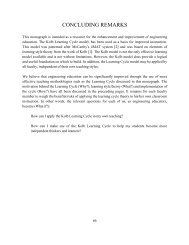
Fig. 9 shows an example <strong>of</strong> a load-displacement diagram<br />
for various cramping torques <strong>of</strong> leaf springs. As seen in this<br />
diagram, the equivalent spring characteristic <strong>of</strong> this system<br />
exhibits a hysteresis loop. At the same time, the s<strong>of</strong>tening<br />
tendency <strong>of</strong> the spring stiffness is large when the cramping<br />
torque is small. From these results, it may be c<strong>on</strong>cluded that<br />
the mirlo-slip occurs at the cramping parts when the<br />
displacement becomes large and, therefore, a large resultant<br />
moment is applied.<br />
If the displacement range is small and the cramping torque<br />
is large, the spring characteristic can be c<strong>on</strong>sidered linear. The<br />
experimental spring c<strong>on</strong>stant in this report is obtained in this<br />
linear range.<br />
Figs. 10 and 11 show the experimental results <strong>of</strong> the spring<br />
c<strong>on</strong>stant compared with the theoretical values. It is seen from<br />
these results that the theoretical values are in good agreement<br />
with experimental results when the width <strong>of</strong> the spring is<br />
relatively small. If width becomes large, however, the experimental<br />
values are smaller than the theoretical values<br />
because <strong>of</strong> micro-slip and insufficient rigidity <strong>of</strong> the cramping<br />
parts.<br />
90<br />
JANUARY 1981, Vol. 103/253<br />
Downloaded 07 Oct 2010 to 128.187.97.3. Redistributi<strong>on</strong> subject to ASME license or copyright; see http://www.asme.org/terms/Terms_Use.cfm
LU<br />
o<br />
DC<br />
O<br />
U.<br />
Q<br />
LJ<br />
DL<br />
<<br />
_J<br />
<<br />
y<br />
ce<br />
><br />
300<br />
200<br />
100<br />
CRAMPING TORQUE<br />
•^ OF LEAF SPR<br />
3"/<br />
-J' / I<br />
' / / / /<br />
/ // J J<br />
1 // ¥ 4<br />
i // J^4~~~~ 7<br />
/ // ^^i /<br />
1 fyS II /<br />
1 [/ / I^J-~-f<br />
1 f _^/-y~/^ /<br />
iy ^**iT III<br />
11^^"^ 1 1 f 1<br />
1 r II III<br />
If II 1 1 ¥<br />
If 1 1 1 1 1<br />
II II I I I<br />
490.3 Ncm<br />
367.7 Ncm<br />
245-2 Ncm<br />
184-4 Ncm<br />
122-6 Ncm<br />
0 0.5<br />
DISPLACEMENT OF TABLE mm<br />
i<br />
1.0<br />
Fig. 9 Load-displacement diagram forh = 1 mm, b = 25 mm, K = 0<br />
0.2 0.4 0.6 0.8<br />
OFFSET FACTOR<br />
Fig. 10 Effect <strong>of</strong> <strong>of</strong>fset factor <strong>on</strong> equivalent spring c<strong>on</strong>stant (h = 1<br />
mm,/ = 132 mm, 7 = 60°, r = 100 mm, E = 96100 N/mm 2 )<br />
Journal <strong>of</strong> Mechanical Design<br />
10 20<br />
WIDTH OF SPRING b mm<br />
Fig. 11 Effect <strong>of</strong> width <strong>of</strong> leaf spring <strong>on</strong> equivalent spring c<strong>on</strong>stant<br />
and natural freq<strong>uency</strong> (h - 1 mm, / = 132 mm, y = 60°, r = 100 mm,<br />
E = 96100 N/mm 2 , « = 0, M = 0.00267 N.sec 2 /mm, J = 33.3<br />
N.mm-sec 2 )<br />
JANUARY 1981, Vol. 103/255<br />
Downloaded 07 Oct 2010 to 128.187.97.3. Redistributi<strong>on</strong> subject to ASME license or copyright; see http://www.asme.org/terms/Terms_Use.cfm
Acknowledgment<br />
The authors gratefully thank Pr<strong>of</strong>essor Y. Jimbo,<br />
University <strong>of</strong> Tokyo, for his generous suggesti<strong>on</strong>s throughout<br />
this work, and also wish to thank Mr. H. NOMURA and Mr.<br />
H. IWASAKI for their kind assistance in experiments.<br />
References<br />
1 Boothroyd.G., and Redford, A.H., Mechanized Assembly, McGraw-Hill,<br />
New York, 1968.<br />
2 Booth, J.H., and McCalli<strong>on</strong>, H., "On Predicting the Mean C<strong>on</strong>veying<br />
Velocity <strong>of</strong> a <strong>Vibratory</strong> C<strong>on</strong>veyor," Proc. Insln. Mech. Engrs. Pt. 1, Vol. 178,<br />
No. 20, 1964, pp. 521-538.<br />
3 Redford, A.H., and Boothroyd, G., "<strong>Vibratory</strong> Feeding," Proc. Instn.<br />
Mech, Engrs., pt. 1, Vol. 182, No. 6, pp. 135-152.<br />
4 Sakaguchi, K., and Taniguchi, O., "Studies <strong>on</strong> <strong>Vibratory</strong> <strong>Feeders</strong>,"<br />
Trans. JSME, Vol. 35, No. 279, 1969, pp. 2183-2189.<br />
5 Morcos, W.A., "On Design <strong>of</strong> Oscillating C<strong>on</strong>veyors," ASME, Journal <strong>of</strong><br />
Engineering for Industry, Vol. 92, No. 1,1970, pp. 53-61.<br />
6 Jimbo, Y., Yokoyama, Y., and Okabe, S., "<strong>Vibratory</strong> C<strong>on</strong>veying," Bull.<br />
Japan Soc. <strong>of</strong>Prec. Engg., Vol. 4, No. 3,1970, pp. 59-64.<br />
7 Mansour, W.A., "Analog and Digital Analysis and Synthesis <strong>of</strong><br />
Oscillatory Track," ASME, Journal <strong>of</strong> Engineering for Industry, Vol. 94, No.<br />
2, 1972, pp. 488-494.<br />
8 Yokoyama, Y., Okabe, S., Nomura, H., and Iwasaki, H., "Setting<br />
Method and Dynamics <strong>of</strong> <strong>Vibratory</strong> <strong>Feeders</strong>," Memoirs <strong>of</strong> the Faculty <strong>of</strong><br />
Technology Kanazawa Univ., Vol. 11, No. 1,1977, pp. 59-69.<br />
256/ Vol. 103, JANUARY 1981 Transacti<strong>on</strong>s <strong>of</strong> the ASME<br />
Downloaded 07 Oct 2010 to 128.187.97.3. Redistributi<strong>on</strong> subject to ASME license or copyright; see http://www.asme.org/terms/Terms_Use.cfm