NONLINEAR CONTROLLER COMPARISON ON A BENCHMARK ...
NONLINEAR CONTROLLER COMPARISON ON A BENCHMARK ...
NONLINEAR CONTROLLER COMPARISON ON A BENCHMARK ...

Create successful ePaper yourself
Turn your PDF publications into a flip-book with our unique Google optimized e-Paper software.
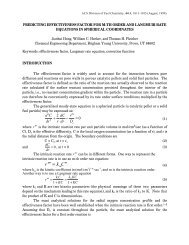
Figure 2.1: Photograph of Flexible Beam System<br />
torque constant of .001 Nm/Amp. The motor served as the only input to the system,<br />
however a strain gauge placed near the xed end of the exible beam senses the<br />
beam's de ection, and an encoder on the motor senses the angular position the proof<br />
mass. The strain gauge is calibrated to give 1 Volt per inch, and the encoder uses a<br />
1024 count disc which in quadrature results in a resolution of 4096 counts/revolution.<br />
The FBS can be mounted in two con gurations, with the exible beam vertically or<br />
horizontally mounted. We choose to mount the beam horizontally so that gravity will<br />
be acting perpendicular to the motion of the system, thus making stabilization more<br />
di cult.<br />
2.2 Derivation of the Mathematical Model<br />
Obtaining an adequate mathematical model for the FBS, one that was not too<br />
complex to be useful nor one that was too simple to be accurate, is a challenge. The<br />
rst step is representing the physical system in a simpler way. Figure 2.2 shows a<br />
simple mechanical model of the system. Here the rigid beam structure is modeled as a<br />
single rigid beam with a point mass (m) located at one end and a motor at the other.<br />
8