Promoting the commercial adoption of lead-free solder and ...
Promoting the commercial adoption of lead-free solder and ...
Promoting the commercial adoption of lead-free solder and ...

Create successful ePaper yourself
Turn your PDF publications into a flip-book with our unique Google optimized e-Paper software.
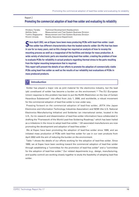
<strong>Promoting</strong> <strong>the</strong> <strong>commercial</strong> <strong>adoption</strong> <strong>of</strong> <strong>lead</strong>-<strong>free</strong> <strong>solder</strong> <strong>and</strong> evaluating its reliability<br />
Report 2<br />
<strong>Promoting</strong> <strong>the</strong> <strong>commercial</strong> <strong>adoption</strong> <strong>of</strong> <strong>lead</strong>-<strong>free</strong> <strong>solder</strong> <strong>and</strong> evaluating its reliability<br />
Hirokazu Tanaka Technical Development Headquarters<br />
Akihiko Saito Measurement <strong>and</strong> Test System Business Division<br />
Toshiro Nagayama Measurement <strong>and</strong> Test System Business Division<br />
Hiromi Umeda Quality Assurance Department<br />
Since April 2002, we at Espec have been mass producing PCBs with <strong>lead</strong>-<strong>free</strong> <strong>solder</strong>. Lead<strong>free</strong><br />
<strong>solder</strong> has different characteristics than <strong>the</strong> <strong>lead</strong>ed eutectic <strong>solder</strong> (Sn-Pb) that has been<br />
in use for so many years, <strong>and</strong> so this change has required an analysis <strong>of</strong> how to revamp <strong>the</strong><br />
mounting process as well as a reappraisal <strong>of</strong> <strong>the</strong> facilities <strong>and</strong> design for mass production. A<br />
wide variety <strong>of</strong> electronic parts are mounted using <strong>lead</strong>-<strong>free</strong> <strong>solder</strong>, creating <strong>the</strong> problem <strong>of</strong> how<br />
to evaluate PCBs for reliability in actual products regarding <strong>the</strong>rmal stress to <strong>the</strong> parts resulting<br />
from <strong>the</strong> higher mounting temperature that is required.<br />
This report will present <strong>the</strong> details <strong>of</strong> our efforts to promote <strong>the</strong> <strong>adoption</strong> <strong>of</strong> <strong>commercial</strong>ly viable<br />
PCBs using <strong>lead</strong>-<strong>free</strong> <strong>solder</strong> as well as <strong>the</strong> results <strong>of</strong> our reliability test evaluations <strong>of</strong> PCBs in<br />
mass produced products.<br />
1 Introduction<br />
Solder has played a major role as joint material for <strong>the</strong> electronics industry, but <strong>the</strong> <strong>lead</strong><br />
(pb) constituent <strong>of</strong> <strong>solder</strong> has become a burden on <strong>the</strong> environment. 1),2) The EU (European<br />
Union) response to this problem has been to put <strong>the</strong> RoHS (Restriction on <strong>the</strong> Use <strong>of</strong> Certain<br />
Hazardous Substances) 3) into effect from July 1, 2006, <strong>and</strong> worldwide, a robust movement<br />
for <strong>the</strong> <strong>commercial</strong> <strong>adoption</strong> <strong>of</strong> <strong>lead</strong>-<strong>free</strong> <strong>solder</strong> is now under way.<br />
Pressing forward on <strong>the</strong> <strong>commercial</strong> <strong>adoption</strong> <strong>of</strong> <strong>lead</strong>-<strong>free</strong> <strong>solder</strong>, JEITA (<strong>the</strong> Japan<br />
Electronics <strong>and</strong> Information Technology Industries Association) <strong>and</strong> NEMI (<strong>the</strong> U.S. National<br />
Electronics Manufacturing Initiative) <strong>and</strong> Soldertec (an international center, located in <strong>the</strong><br />
U.K., for tin research <strong>and</strong> dissemination <strong>of</strong> <strong>lead</strong>-<strong>free</strong> <strong>solder</strong> information) have collaborated in<br />
drafting <strong>the</strong> "Framework <strong>of</strong> <strong>the</strong> World Lead-<strong>free</strong> Soldering Roadmap," which has been hailed<br />
as a milestone in <strong>the</strong> move to adopt <strong>lead</strong>-<strong>free</strong> <strong>solder</strong>. 4) All associated manufacturers are now<br />
promoting <strong>the</strong> development <strong>and</strong> <strong>adoption</strong> <strong>of</strong> <strong>lead</strong>-<strong>free</strong> <strong>solder</strong>. 5)<br />
We at Espec have been promoting <strong>the</strong> <strong>adoption</strong> <strong>of</strong> <strong>lead</strong>-<strong>free</strong> <strong>solder</strong> since 1999, <strong>and</strong> we<br />
initiated mass production <strong>of</strong> PCBs with <strong>lead</strong>-<strong>free</strong> <strong>solder</strong> for use in our own products from<br />
April 2002 with <strong>the</strong> aim <strong>of</strong> reducing <strong>the</strong> burden on <strong>the</strong> environment.<br />
Table 1 shows <strong>the</strong> details <strong>of</strong> our efforts working for <strong>the</strong> <strong>adoption</strong> <strong>of</strong> <strong>lead</strong>-<strong>free</strong> <strong>solder</strong>. Since<br />
1999, we at Espec have been working toward <strong>the</strong> <strong>commercial</strong> <strong>adoption</strong> <strong>of</strong> <strong>lead</strong>-<strong>free</strong> <strong>solder</strong><br />
through establishing a "committee for <strong>the</strong> promotion <strong>of</strong> <strong>lead</strong>-<strong>free</strong> <strong>solder</strong>" <strong>and</strong> a "committee<br />
for <strong>the</strong> <strong>adoption</strong> <strong>of</strong> <strong>lead</strong>-<strong>free</strong> <strong>solder</strong>." Our related departments (e.g., design, manufacturing,<br />
<strong>and</strong> quality control) are working closely toge<strong>the</strong>r to study <strong>the</strong> feasibility <strong>of</strong> adopting <strong>lead</strong>-<strong>free</strong><br />
<strong>solder</strong>.<br />
ESPEC Technology Report No.17 10
<strong>Promoting</strong> <strong>the</strong> <strong>commercial</strong> <strong>adoption</strong> <strong>of</strong> <strong>lead</strong>-<strong>free</strong> <strong>solder</strong> <strong>and</strong> evaluating its reliability<br />
2 Efforts to adopt PCBs compatible with <strong>lead</strong>-<strong>free</strong> <strong>solder</strong><br />
Table 2 shows <strong>the</strong> details <strong>of</strong> <strong>the</strong> efforts we have made for <strong>the</strong> <strong>adoption</strong> <strong>of</strong> <strong>lead</strong>-<strong>free</strong> <strong>solder</strong>.<br />
The results <strong>of</strong> our investigations into processes <strong>and</strong> materials for parts, design, <strong>and</strong><br />
manufacturing are presented below.<br />
Design<br />
Manufacturing<br />
Parts<br />
Table 2 Details <strong>of</strong> efforts for <strong>the</strong> <strong>adoption</strong> <strong>of</strong> <strong>lead</strong>-<strong>free</strong> <strong>solder</strong><br />
Processes <strong>and</strong> materials Details <strong>of</strong> efforts<br />
PCBs<br />
Metal masks<br />
Reflow <strong>solder</strong>ing<br />
process<br />
Flow <strong>solder</strong>ing<br />
process<br />
Manual <strong>solder</strong>ing<br />
process<br />
Abolished <strong>solder</strong> finish (hot-air <strong>solder</strong> leveling). Instituted<br />
pre-flux (OSP).<br />
Reappraised <strong>and</strong> improved circuit l<strong>and</strong> pattern size.<br />
Added PCB identifying marking (<strong>lead</strong>-<strong>free</strong> label) (Fig.1-a).<br />
Improved screen aperture.<br />
Improved position <strong>of</strong> printed circuits, hole precision, <strong>and</strong><br />
precision <strong>of</strong> mounting position.<br />
Made trapezoidal pr<strong>of</strong>ile with temperature control inside<br />
reflow oven (Fig.1-b).<br />
Controlled peak temperature (max. 240℃).<br />
Made temperature distribution uniform.<br />
Reappraised <strong>solder</strong> paste shelf life <strong>and</strong> useful life after<br />
opening.<br />
Ensured complete through-hole wetting (streng<strong>the</strong>ned<br />
pre-heat control).<br />
Instituted measures preventing temperature drop during<br />
<strong>solder</strong> injection.<br />
Modified nozzle discharge tip (extended immersion time).<br />
Took countermeasures to dross (<strong>solder</strong> oxides)<br />
Reappraised control st<strong>and</strong>ards for <strong>solder</strong> constituents<br />
(adjusted to min. Pb = 0.5%, Cu = 0.9%)<br />
Reappraised <strong>solder</strong>ing training st<strong>and</strong>ards <strong>and</strong> retrained.<br />
Reserved special tools <strong>and</strong> special work area.<br />
Prohibited use <strong>of</strong> cut <strong>solder</strong> wire.<br />
Modified temperature <strong>of</strong> <strong>solder</strong>ing gun (from 350℃ to 370<br />
or 380℃).<br />
Reconfirmed heat resistance temperature.<br />
Confirmed surface finish materials (plating) <strong>of</strong> parts.<br />
For <strong>the</strong> "design" <strong>of</strong> PCBs, <strong>the</strong> conventional <strong>solder</strong> finish (hot-air <strong>solder</strong> leveling) was<br />
abolished to eliminate <strong>lead</strong> contamination, <strong>and</strong> <strong>the</strong> copper pattern <strong>and</strong> pre-flux (OSP,<br />
Organic Solderability Preservative) were consolidated. An identifying mark (Fig.1-a) was<br />
added to <strong>the</strong> <strong>lead</strong>-<strong>free</strong> <strong>solder</strong> PCBs to aid in recycling <strong>and</strong> in service inspections <strong>of</strong> <strong>the</strong><br />
mounting PCBs.<br />
ESPEC Technology Report No.17 12
<strong>Promoting</strong> <strong>the</strong> <strong>commercial</strong> <strong>adoption</strong> <strong>of</strong> <strong>lead</strong>-<strong>free</strong> <strong>solder</strong> <strong>and</strong> evaluating its reliability<br />
15<br />
Evaluation <strong>solder</strong><br />
materials<br />
PCB materials<br />
Temperature cycle<br />
test<br />
High temperature<br />
test<br />
High-temperature,<br />
high-humidity test<br />
Mixed gas test<br />
Field reliability<br />
testing<br />
Evaluation items<br />
Table 3 Evaluation materials <strong>and</strong> conditions<br />
Lead-<strong>free</strong> <strong>solder</strong>: Sn-Ag-Cu<br />
Leaded <strong>solder</strong>: Sn-Pb eutectic <strong>solder</strong><br />
Glass epoxy (FR-4, t = 1.6 mm)<br />
-25℃←→+80℃<br />
Duration: 30 min. each temperature (1 hour/cycle)<br />
1000 (3000) cycles<br />
+80℃, 1000 hours<br />
+80℃, 90%, 1000 hours<br />
+25℃, 75%, H2S = 0.01 ppm, SO2 = 0.2 ppm<br />
NO2 = 0.2 ppm, Cl2 = 0.01 ppm, 500 hours<br />
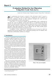
Installation equipment: Temperature <strong>and</strong> humidity chamber<br />
(Model name: Platinous Series)<br />
Facilities sites: Espec Utsunomiya Technocomplex,<br />
Fukuchiyama Plant<br />
Check operation (e.g., input <strong>and</strong> output, temperature <strong>and</strong><br />
humidity characteristics).<br />
Measure power consumed, measure shear strength.<br />
Observe appearance <strong>and</strong> cross sections.<br />
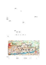
(a) Portion <strong>of</strong> evaluation PCBs (b) Field reliability testing conditions<br />
Photo 1 Evaluation PCBs <strong>and</strong> test conditions<br />
ESPEC Technology Report No.17
From <strong>the</strong> results <strong>of</strong> <strong>the</strong> reliability tests showing no failure <strong>of</strong> <strong>the</strong> <strong>lead</strong>-<strong>free</strong> product PCBs<br />
even after 3000 cycles, for estimated life in worst case condition C we get <strong>the</strong> following.<br />
3000 cycles x 4.5 (acceleration constant) = 13,500 cycles<br />
13,500 / (twice x 365 days) = approximately 18.5 years<br />
This provides an estimated life <strong>of</strong> 18.5 years at field conditions. However, in estimated life,<br />
we must allow for a safety coefficient taking into account <strong>the</strong> degree <strong>of</strong> product completion,<br />
<strong>solder</strong> usage environment settings, <strong>and</strong> different usage conditions. In <strong>the</strong> future, we plant to<br />
verify <strong>the</strong>se estimates using <strong>the</strong> results <strong>of</strong> continuous field reliability testing.<br />
Accelerated test<br />
conditions<br />
Field conditions<br />
A<br />
B<br />
C<br />
4 Conclusion<br />
<strong>Promoting</strong> <strong>the</strong> <strong>commercial</strong> <strong>adoption</strong> <strong>of</strong> <strong>lead</strong>-<strong>free</strong> <strong>solder</strong> <strong>and</strong> evaluating its reliability<br />
Table 4 Acceleration coefficient estimates using<br />
Manson-C<strong>of</strong>fin's modified formula<br />
Minimum<br />
temperature<br />
-25℃<br />
+25℃<br />
+35℃<br />
+25℃<br />
Maximum<br />
temperature<br />
+80℃<br />
+50℃<br />
+60℃<br />
+60℃<br />
△T<br />
(temperature width)<br />
24 cycles/day<br />
2 cycles/day<br />
Acceleration constant<br />
(1/AF) for accelerated<br />
testing using field<br />
conditions<br />
For this report, we obtained results <strong>of</strong> reliability evaluations from our efforts to adopt<br />
<strong>commercial</strong>ly viable PCBs using <strong>lead</strong>-<strong>free</strong> <strong>solder</strong>, <strong>and</strong> we arrived at <strong>the</strong> following<br />
conclusions.<br />
(1) By reappraising <strong>the</strong> manufacturing <strong>and</strong> design processes to adopt <strong>lead</strong>-<strong>free</strong> <strong>solder</strong> for<br />
mass production, we found that it is possible to maintain mountability equivalent to or<br />
better than that <strong>of</strong> conventional <strong>lead</strong>ed <strong>solder</strong>.<br />
However, for manual <strong>solder</strong>ing processes, difficulty in improving workability remains<br />
due to <strong>the</strong> characteristics <strong>of</strong> <strong>lead</strong>-<strong>free</strong> <strong>solder</strong> compared to conventional <strong>lead</strong>ed <strong>solder</strong>.<br />
(2) The higher mounting temperatures <strong>and</strong> <strong>the</strong> resulting <strong>the</strong>rmal stress on parts when<br />
adopting <strong>lead</strong>-<strong>free</strong> <strong>solder</strong> were confirmed not to pose any problems in regard to <strong>the</strong><br />
mounting conditions <strong>and</strong> reliability test evaluation items used in <strong>the</strong>se experiments.<br />
(3) Product PCBs using <strong>lead</strong>-<strong>free</strong> <strong>solder</strong> have exhibited <strong>the</strong> ability to withst<strong>and</strong> a minimum<br />
<strong>of</strong> 3000 cycles in temperature cycle tests <strong>and</strong> a minimum <strong>of</strong> 20 thous<strong>and</strong> hours in field<br />
reliability testing.<br />
ESPEC Technology Report No.17 20<br />
△105℃<br />
△25℃<br />
△25℃<br />
△35℃<br />
on/<strong>of</strong>f<br />
frequency<br />
AF=1<br />
1/9.7<br />
1/8.5<br />
1/4.5
<strong>Promoting</strong> <strong>the</strong> <strong>commercial</strong> <strong>adoption</strong> <strong>of</strong> <strong>lead</strong>-<strong>free</strong> <strong>solder</strong> <strong>and</strong> evaluating its reliability<br />
21<br />
From <strong>the</strong> results <strong>of</strong> our evaluations as seen above, we can assume that it is possible to<br />
maintain reliability equivalent to or better than that <strong>of</strong> conventional <strong>lead</strong>ed <strong>solder</strong> when<br />
using <strong>lead</strong>-<strong>free</strong> <strong>solder</strong> on PCBs. We <strong>the</strong>refore conclude that it is possible to use <strong>lead</strong>-<strong>free</strong><br />
<strong>solder</strong> in mass production.<br />
Based on <strong>the</strong>se results, we at Espec intend to continue promoting <strong>the</strong> <strong>adoption</strong> <strong>of</strong> <strong>lead</strong>-<strong>free</strong><br />
<strong>solder</strong>.<br />
[Bibliography]<br />
1) Katsuaki Suganuma, "The current status <strong>of</strong> <strong>lead</strong>-<strong>free</strong> <strong>solder</strong>ing," ESPEC Technology<br />
Report, No.13, p.1-8, 2002<br />
2) Masamitsu Aoki, "Environmental information on Electronics Industries from Europe,"<br />
Journal <strong>of</strong> Japan Institute Electronics Packaging, Vol.5, No.3, p.227-232, 2002<br />
3) The Council <strong>of</strong> European Union, "Directive <strong>of</strong> <strong>the</strong> European Parliament <strong>and</strong> <strong>of</strong> <strong>the</strong> Council<br />
on <strong>the</strong> restriction <strong>of</strong> <strong>the</strong> use <strong>of</strong> certain hazardous substances in electrical <strong>and</strong> electronic<br />
equipment" Official Journal <strong>of</strong> <strong>the</strong> European Union, Feb. 12, 2003<br />
4) JEITA, "Framework <strong>of</strong> <strong>the</strong> World Lead-<strong>free</strong> Soldering Roadmap," JEITA, Dec. 17, 2002<br />
5) Kenichiro Suetugu, "Development <strong>of</strong> flow <strong>and</strong> reflow <strong>solder</strong>ing technology for <strong>lead</strong> <strong>free</strong><br />
<strong>solder</strong>," JISSO/PROTEC forum Japan 2002 Proceedings, p.154-164, 2002<br />
6) Hirokazu Tanaka, Yuichi Aoki <strong>and</strong> Hiroko Katayanagi, "Evaluation results on reliability <strong>of</strong><br />
<strong>lead</strong>-<strong>free</strong> <strong>solder</strong> -Tabai Espec efforts to develop viable <strong>lead</strong>-<strong>free</strong> <strong>solder</strong>-," ESPEC<br />
Technology Report, No.11, p.9-18, 2001<br />
7) St<strong>and</strong>ard <strong>of</strong> Electronics Industries Association <strong>of</strong> Japan, "Environmental <strong>and</strong> endurance<br />
test methods for CSP/BGA package on mounting condition," EIAJ ET-7407, 1999<br />
8) Makoto Kitano, Tetsuro Kumazawa, Michiharu Honda <strong>and</strong> Kazuo Hirota, "A method <strong>of</strong><br />
determining reliability testing conditions for <strong>solder</strong> joints <strong>of</strong> electronic devices," Journal<br />
<strong>of</strong> <strong>the</strong> Japan Society <strong>of</strong> Mechanical Engineers, Vol.62, No.598, p.166-173, 1996<br />
9) Ikuo Shoji, Hideo Mori <strong>and</strong> Yasumitsu Orii, "Thermal Fatigue strength evaluation <strong>of</strong><br />
0.5mm pitch CSP <strong>solder</strong> joints," 5th Symposium on Microjoining <strong>and</strong> Assembly<br />
Technology in Electronics, p.137-142, 1999<br />
10) Minoru Mukai, "Stress analysis to <strong>the</strong> reliability design <strong>of</strong> <strong>solder</strong> joints," 7th Symposium<br />
on Microjoining <strong>and</strong> Assembly Technology in Electronics, p.27-34, 2001<br />
11) Masaki Watanabe, Yasuo Yokota <strong>and</strong> Atsuhito Mochida, "Evaluation <strong>of</strong> acceleration<br />
factor on Sn-Ag-Cu/Sn-Zn-Bi hybrid structure Pb <strong>free</strong> CSP," 12th Japan Institute<br />
Electronics Packaging Micro Electronics Symposium, p.207-210, 2002<br />
12) Shubhada Sahasrabudhe, Eric Monroe <strong>and</strong> Sharabh T<strong>and</strong>on, "Underst<strong>and</strong>ing <strong>the</strong> effect<br />
<strong>of</strong> dwell time on figure life <strong>of</strong> packages using <strong>the</strong>rmal shock <strong>and</strong> intrinsic material<br />
behavior," IEEE 2003 ECTC proceedings, p.898-904, 2003<br />
ESPEC Technology Report No.17