download
download
download

You also want an ePaper? Increase the reach of your titles
YUMPU automatically turns print PDFs into web optimized ePapers that Google loves.
Technical information for our customers<br />
technology report<br />
Special issue:<br />
Evaluating Reliability<br />
Understanding the Technology<br />
What is Environmental Testing? Part 2<br />
A Consideraton of Methods for Evaluating<br />
Reliability of Electric Parts<br />
Explanation of International<br />
Standard IEC 68-2-66<br />
Agribusiness<br />
1<br />
13<br />
18<br />
22
Our<br />
Philosophy<br />
Corporate Data<br />
TABAI ESPEC CORP.<br />
Company Name: TABAI ESPEC CORP.<br />
Date founded: July 25, 1947<br />
Date Incorporated: January 13, 1954<br />
Paid-up Capital: 6,778,900,000 Yen<br />
(As of March, 1996)<br />
Chairman: Eiichi Koyama<br />
President: Kiyoshi Shimazaki<br />
Senior<br />
Managing Director: Yoshinobu Yamada<br />
Managing Directors: Susumu Nojii<br />
Toshikazu Adachi<br />
Nobuyoshi Shin<br />
Directors: Toichi Ogura<br />
Katsuyuki Kakihara<br />
Auditors: Katsuharu Nakano<br />
Shoichiro Yoshioka<br />
Takuichi Omura<br />
Employees: 613 Persons<br />
Head Office:<br />
3-5-6, Tenjinbashi, Kita-ku,<br />
Osaka 530, Japan<br />
Phone: (81) 6-358-4741<br />
Fax: (81) 6-358-5500<br />
Telex: 05233629 TBI J<br />
Kuala Lumpur Representative Office:<br />
Temp Girl Business Center 4th. Floor,<br />
Secondary Tower Block Wisma MCIS,<br />
Jalan Barat 46700 Petaling Jaya,<br />
Selangor, Malaysia<br />
Phone: (60) 3-7544277<br />
Fax: (60) 3-7544290<br />
Metropolitan Area Office:<br />
Yokohama (Kanagawa)<br />
Sales Offices:<br />
Osaka, Tokyo, Yokohama, Sendai, Omiya,<br />
Tsukuba, Hino, Matsumoto, Shizuoka,<br />
Nagoya, Kanazawa, Hiroshima,<br />
Niihama, Fukuoka<br />
Plant: Fukuchiyama (Kyoto)<br />
Technical Center: Neyagawa (Osaka)<br />
Technocomplex: Utsunomiya (Tochigi)<br />
We at TABAI ESPEC are continually pursuing perfection. In our ongoing struggle to<br />
realize this ideal, we have established our Corporate Mind, which we proudly use as the<br />
basis for all our efforts. This Corporate Mind defines for us our present and future goals,<br />
directions and actions. At TABAI ESPEC, where “Environment” is our business, we offer<br />
aid for new technological developments and a more certain and improved living<br />
environment. With “Progress to Perfection” as our corporate policy, we aim to become the<br />
company, firstly “with public recognition by having our original line of business, and our<br />
own original product sphere by virtue of our original technology”, and secondly “with<br />
intellectual raison d’être of such that as specialists can, assist our clients and industry in<br />
setting up various issues and in finding answers to them”. This total concept we call<br />
ESPEC. From our internationally minded product development, to our thorough<br />
after-service, all our activities originate in this concept of ESPEC. ESPEC is the<br />
foundation upon which we manufacture products with superb performance, functional<br />
design and excellent cost-performance — our ESPEC.<br />
ESPEC — our philosophy, our goal.<br />
The ESPEC Group (Affiliated Companies)<br />
ESPEC CORP. (U.S.A.)<br />
425 Gordon Industrial Court, S.W.<br />
Grand Rapids, MI 49509, USA<br />
Phone: (1) 616-878-0270<br />
Fax: (1) 616-878-0280<br />
SHANGHAI ESPEC<br />
ENVIRONMENTAL EQUIPMENT CORP. (CHINA)<br />
Ha-mi Road 166 Shanghai, China<br />
Phone·Fax: (86) 21-62394953<br />
GUANGZHOU ESPEC<br />
ENVIRONMENTAL EQUIPMENT CO., LTD. (CHINA)<br />
1 Zhu Si Gang, Dong Guan Zhuang Road,<br />
Guangzhou, China<br />
Phone·Fax: (86) 20-8772-5042<br />
TABAI ESPEC SERVICE CORP. (JAPAN)<br />
TABAI KANKYO SETSUBI CO., LTD. (JAPAN)<br />
TABAI ESPEC KYOTO CORP. (JAPAN)<br />
TABAI ESPEC HYOGO CORP. (JAPAN)<br />
Product Guide<br />
Environmental Test Chambers<br />
Temperature (& Humidity) Chamber<br />
Temperature (Humidity) & Vibration<br />
Combined Environmental Test Chamber<br />
Walk-in Type Temperature (& Humidity) Chamber<br />
HAST System (Highly Accelerated Stress Test System)<br />
Thermal Shock Chamber<br />
Temperature Chamber (Industrial Ovens)<br />
Environmental Test Chamber Network, E-bus<br />
Burn-in Test Systems<br />
ECL Testing Burn-in System<br />
Flash Memory E/W Cycle Test System<br />
Automatic Burn-in System<br />
LCD Production Equipments<br />
Automatic Clean Cure System<br />
Single Loading Plate Clean Oven<br />
Laboratory Chambers<br />
Biomedical Chambers<br />
Agribusiness<br />
Plant Factory<br />
Phyto-tron (Environmental Control Chamber for Plant)<br />
Growth Chamber<br />
NOTE:<br />
Some models are available only in the limited countries.
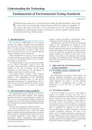
Understanding the Technology<br />
What is Environmental Testing? Part 2<br />
One method of improving the quality of all industrial products is to confirm their<br />
quality through environmental testing. To achieve this confirmation, “test<br />
planning”, “test execution”, and “analyzing test results” must be carried out<br />
together as one unit.<br />
We are presenting this explanatory series summarizing “environmental testing” for<br />
those people who may have heard of environmental testing but aren’t aware of what it<br />
means.<br />
In this article, the second in the series, we shall discuss “humidity testing”.<br />
1. Introduction<br />
Environmental testing reportedly got its start during<br />
World War II, when the United States military was experiencing<br />
an unusually high failure rate for some of its<br />
military equipment. The story goes that 60% of electronic<br />
equipment for aircraft use sent from the US to SE<br />
Asia was unusable on arrival. In addition, 50% of the<br />
spare electronic equipment stored in warehouses already<br />
failed when they were stored. Most of the failures<br />
could be considered caused directly by humidity or by<br />
humidity combined with some other factor.<br />
*Overseas Business Department<br />
1. Introduction<br />
Contents<br />
2. Influence of High Humidity Environment<br />
2-1 Examples of general failures caused by high humidity<br />
2-1-1 Failure due to corrosion of plastic sealed semiconductor devices<br />
2-1-2 Failures due to migration on printed circuit boards<br />
3. High Humidity Testing Methods<br />
3-1 High Humidity Testing Methods for Semiconductor Devices<br />
3-1-1 Temperature-Humidity Bias Test (THB)<br />
3-1-2 Pressure Cooker Test (PCT) and Unsaturated Pressure Cooker Test<br />
(USPCT)<br />
Yoshinori Kin*<br />
3-1-3 Acceleration in tests for humidity resistance of semiconductor devices<br />
3-1-4 A comparison of the merits and demerits of high humidity tests<br />
3-2 Ion Migration Test Method for Printed Circuit Boards<br />
3-3 Humidity Testing Precautions<br />
4. Test Equipment for Humidity Testing<br />
Humidity is one of the main environmental factors<br />
that cause equipment to fail. At this point, we would like<br />
to discuss such issues as the effects of a high humidity<br />
environment on the widely used semiconductor devices<br />
and printed circuit boards, which it is no exaggeration to<br />
say are used in almost every type of equipment. We also<br />
intend to look at the testing methods for the influence of<br />
such a high humidity environment.<br />
ESPEC TECHNOLOGY REPORT NO.2 1
2. Influence of High Humidity Environment<br />
2-1 Examples of general failures caused by<br />
high humidity<br />
Table 1 shows the principal failures caused by humidity.<br />
General<br />
classification<br />
Humidity<br />
Moisture<br />
absorption<br />
Corrosion<br />
Migration<br />
Mildew<br />
Failure<br />
Intermediate<br />
classification<br />
or cause<br />
Failure mode<br />
Dispersion Swelling<br />
Degradation of<br />
insulation<br />
Deliquescence<br />
Failures due to humidity can be classified into a number<br />
of categories as in table 1, but here we would like to<br />
focus on corrosion and migration in a little more detail.<br />
2-1-1 Failure due to corrosion of plastic packaged<br />
semiconductor devices<br />
Integrated circuit chips form a large number of components<br />
on silicon substrate, and these components are<br />
connected by wiring to form circuits. Aluminum and<br />
aluminum alloys are often used in this wiring because<br />
they are economical and easy to process.<br />
From the time plastic packaged integrated circuits<br />
first began to be produced, corrosion caused by moisture<br />
penetrating the package and causing open circuits<br />
the aluminum wiring had to be confronted as a major<br />
problem. Efforts were made to improve quality using<br />
Environmental conditions<br />
used<br />
Susceptible parts and materials<br />
Humidity Parts sealed, covered, or constructed using<br />
polar resins with low crystallization (e.g.,<br />
polyamides and polyvinyl alcohol and<br />
phenolic resins), and parts generating low<br />
heat<br />
Hydrolysis Chemical change Temperature + humidity Polycarbonate, polyester,<br />
polyoxymethylene,<br />
polybutadiene terephthalate<br />
Fine cracks<br />
(Hairline<br />
(cracks,<br />
(Breathing)<br />
Battery<br />
corrosion<br />
Electrolysis<br />
corrosion<br />
Crevice<br />
corrosion<br />
Stress<br />
corrosion<br />
cracks<br />
Hydrogen<br />
embrittlement<br />
Moisture<br />
penetration<br />
Degradation of<br />
insulation<br />
Deliquescence<br />
Color change<br />
Increased<br />
resistance<br />
Open circuit<br />
Humidity<br />
{ heat shock,<br />
temperature cycle } + humidity<br />
Temperature/humidity cycle<br />
Electrial potential from<br />
humidity + contact with<br />
foreign metal<br />
Resin covered or sealed parts<br />
Connector contacting electric potential of<br />
0.2 V or more requires caution<br />
Humidity + DC electric field E.g., resistors, resin sealed ICs<br />
Humidity Cracks (e.g., terminals)<br />
Damage Ammonia (copper alloy)<br />
Chloride (stainless)<br />
Ion migration Short circuit<br />
Insulation defect<br />
Table 1 Principal failures caused by humidity<br />
Insulation defect<br />
Quality variation<br />
Decomposition<br />
Corrosion<br />
Plating acid bath Steel<br />
Alloys (e.g., brass, nickel silver, stainless)<br />
Humidity + DC electric field Bi, Cd, Cu, Pb, Sn, Zn, Ag<br />
Humidity + DC electric field<br />
+ halogen ions<br />
Temperature (25 - 35°C) +<br />
humidity (min. 90%)<br />
Metals that migrate when coexisting with<br />
halogen : Au, In, Pd, Pt<br />
Plastic materials (e.g., polyurethane,<br />
polyvinyl chloride, epoxy, acrylic, silicon,<br />
polyamide, phthalic acid resin)<br />
Kiyoshige Echikawa: From the “Reliability Test of Electronic Components” (1985) Union of Japanese Scientists and Engineers<br />
resin materials, improving mold technology, and improving<br />
passivation film, but semiconductor devices<br />
have continued to be miniaturized, and so corrosion of<br />
packaged aluminum wiring is still a major problem today.<br />
The process of generating corrosion in aluminum<br />
wiring can be understood as follows.<br />
2 ESPEC TECHNOLOGY REPORT NO.2
· No bias voltage applied<br />
The bonding pad corrodes significantly. (The<br />
bonding pad has no water resistant film<br />
[= passivation film].)<br />
· Bias voltage applied<br />
(Anode side reaction)<br />
➀ Under normal environmental conditions, the surface<br />
of aluminum is passivated with an oxide film, and<br />
aluminum is stable.<br />
➁ When bias is applied to aluminum wiring protected by<br />
passive state gibbsite [appearing as Al2O3 ·3H2O, or<br />
Al(OH)3], the aluminum dissolves according to the<br />
following reactions, due to the anode surface absorbing<br />
moisture and Cl – ions had been expanding inside<br />
the resin package.<br />
➂ First, surface hydroxides react to Cl – ions, forming<br />
soluble salts.<br />
Al(OH)3 + Cl – ® Al(OH)2Cl + OH – . . . . . . (1)<br />
➃ The substrate aluminum exposed because of this reaction<br />
then reacts with the Cl – ions.<br />
Al + 4Cl – ® Al Cl4 – + 3e – . . . . . . . . . . . . . . . (2)<br />
➄ Once again, the absorbed moisture, caused by humidity<br />
penetrating inside the resin package, produces the<br />
following reaction.<br />
AlCl4 – + 3H2O ® Al(OH)3 + 3H + + 4Cl. . . (3)<br />
➅ Finally, this becomes Al(OH)3. The Al(OH)3 formed<br />
here, unlike the protective oxide film, does not form a<br />
seal. In addition, this product has a ratio of cubic expansion<br />
high enough to cause cracking in the protective<br />
oxide film, thus promoting corrosion.<br />
➆ The Cl – ions formed in formula (3) are again consumed<br />
by reactions in formulas (1) and (2).<br />
Through this chain reaction, a small quantity of Cl –<br />
ions can produce a large amount of corrosion.<br />
➇ However, in a competing reaction, anodic oxidation<br />
occurs, and corrosion is suppressed as the oxidized<br />
layer thickens.<br />
The corrosion reaction of Aluminum changes depending<br />
on whether bias voltage is applied. The following<br />
factors are thought to accelerate Aluminum<br />
corrosion.<br />
➀ Poor adhesion between resin and lead frame<br />
interface (Due to the difference in each rate of<br />
expansion)<br />
Moisture penetration routes<br />
· Moisture permeates through the package.<br />
· Moisture penetrates through the resin and lead<br />
frame interface.<br />
Corrosion of Aluminum Wiring<br />
Moisture reaches the chip<br />
surface.<br />
(Cathode side reaction)<br />
➀ The concentration of hydrogen ions near the electrodes<br />
increases due to the absorption of moisture by<br />
the resin package, along with the reduction of oxygen<br />
caused by applying bias [formula (4)] as well as the<br />
generation of hydrogen [formula (5)].<br />
O2 + 2H2O + 4e – ® 4(OH) – . . . . . . . . . . . . (4)<br />
H2O+ e – ® (OH) – + (1/2)H2. . . . . . . . . . . . . (5)<br />
➁ In the presence of flaws such as pinholes, voids, and<br />
cracks in the oxide film protecting the aluminum, the<br />
OH – ions formed here are diffused to the aluminum<br />
substrate, and the following reaction forms aluminum<br />
hydroxide just as at the anode.<br />
Al + 3(OH) – ® Al(OH)3 + 3e – . . . . . . . . . . . (6)<br />
➂ The OH – ions formed in the reaction in formula (5)<br />
are consumed in the reaction forming the aluminate<br />
ions, as follows:<br />
OH – + Al + H2O ® AlO2 – + (3/2)H2 . . . . . (7)<br />
At the cathode, reaction forming OH – ions continues.<br />
This reaction is limited by current density.<br />
➃ The following reactions, utilizing cations such as Na +<br />
and K + inside the resin package, cause an increase in<br />
the concentration of OH – ions,<br />
Na + + e – ® Na . . . . . . . . . . . . . . . . . . . . . . . . (8)<br />
Na + H2O ® Na + + OH – + (1/2)H2 . . . . . . (9)<br />
promoting the reaction in formula (6), and so increasing<br />
corrosion.<br />
➄ Since aluminum is an amphoteric metal, acidic as well<br />
as alkaline electrolytic solutions form at the cathode,<br />
causing corrosion.<br />
2Al + 6H + ® 2Al 3+ + 3H2 . . . . . . . . . . . . . (10)<br />
2Al 3+ + 6H2O ® 2Al(OH)3 + 6H + . . . . . . (11)<br />
The hydrogen ions formed in the reaction in formula<br />
(9) are again consumed in the reaction in formula (8),<br />
promoting corrosion through a chain reaction.<br />
From the “Semiconductor Device Reliability Handbook” (1988) of Matsushita Electronics Corporation<br />
➁ Sealing materials are adulterated with impurities,<br />
or tainted by ions of impurities during assembly.<br />
(Due to the presence of impurities)<br />
➂ A high concentration of phosphorus used in the<br />
passivation film<br />
➃ Defects in the passivation film<br />
ESPEC TECHNOLOGY REPORT NO.2 3
2-1-2 Failures due to migration on printed circuit<br />
boards<br />
Migration refers to the movement of matter.<br />
Recently the problem of a high humidity environment<br />
causing ion migration (also called Electrochemical<br />
Migration) on printed circuit boards has become<br />
more serious due to the following reasons.<br />
· The miniaturization of electric products concurrent<br />
with higher level functions has promoted finer wiring<br />
and increased layers of printed circuit boards.<br />
· As electric products have become miniaturized, such<br />
products as computers and telephones have become<br />
mobile, bringing a corresponding increase in the severity<br />
of environmental stress.<br />
Mechanism generating ion migration<br />
When printed circuit boards absorb moisture in the<br />
area between the metal of the wiring, and then bias voltage<br />
is applied, metal from the anode is ionized and<br />
moves toward the cathode. The reduced metal from the<br />
cathode then extends toward the anode as dendrites.<br />
If the reduced metal reaches the anode, short circuits<br />
and insulation defects occur between the wires.<br />
Photo. 1 Example of ion migration<br />
The acceleration factors for generating this type of<br />
ion migration can be understood as follows.<br />
➀ Moisture absorption or dew condensation on the<br />
printed circuit board material in the space between<br />
the metal patterns<br />
➁ Temperature change of the printed circuit board<br />
➂ Strong and weak bias voltage applied<br />
➃ Distance between the metal patterns<br />
➄ Ionized foreign matter such as halogen and alkali<br />
adhering to the surface of the printed circuit board<br />
· CFC (chlorofluorocarbon) regulations have changed<br />
the methods of cleaning such equipment as printed<br />
circuit boards, increasing the possibility of ion migration<br />
caused by flux that has been left due to poor<br />
treatment.<br />
· There has been an increase in the number of printed<br />
circuit boards with current constantly applied, such<br />
as in the pre-heating function of televisions, causing<br />
ion migration to form more quickly.<br />
In the field of electronic devices, migration is generally<br />
classified into the three major categories of ion migration,<br />
electromigration, and stress migration. In this<br />
article we shall discuss the serious problem of ion migration<br />
as it relates to humidity.<br />
Cu Cu<br />
Dissolved –<br />
Cl<br />
Deposited<br />
Moisture<br />
Metal ions supplied Migrated metal deposited<br />
and extended<br />
Fig.1 The mechanism generating ion migration<br />
4 ESPEC TECHNOLOGY REPORT NO.2
3. High Humidity Testing Methods<br />
Now, to give one example of high humidity testing<br />
methods, we shall discuss testing methods for semiconductor<br />
devices.<br />
3-1 High Humidity Testing Methods for<br />
Semiconductor Devices<br />
A large number of high humidity tests have been performed<br />
to evaluate aluminum corrosion in the early<br />
stages.<br />
Those testing methods are shown in Table 2.<br />
These testing methods can be broadly classified into<br />
two types: methods that leave the semiconductor devices<br />
in a high humidity environment, and methods that<br />
apply bias voltage to the semiconductor devices while<br />
they are in high humidity.<br />
We must be very careful to clearly understand one<br />
point, that the failure mode differs for each testing<br />
method.<br />
3-1-1 Temperature-Humidity Bias Test (THB)<br />
As one method of high humidity testing, this test has<br />
changed from 40°C at 90%RH ® 60°C at 90%RH ®<br />
85°C at 85%RH, improving reliability as test conditions<br />
have become more severe.<br />
This 85°C 85%RH test is the most common test today,<br />
and is standardized in such standards as IEC 749,<br />
Semiconductor Device Mechanical and Climatic Test<br />
Methods, and JIS C 7021, Type Designation System for<br />
Discrete Semiconductor Devices.<br />
No. Test item Details<br />
1<br />
2<br />
Temperature-humidity<br />
storage test<br />
Temperature-humidity<br />
bias test (THB)<br />
Exposing devices to an atmosphere of<br />
fixed temperature and relative humidity<br />
(less than 100%RH)<br />
3-1-2 Pressure Cooker Test (PCT) and Unsaturated<br />
Pressure Cooker Test (USPCT)<br />
Progress is again being made in improving reliability<br />
of semiconductor devices, and many semiconductor devices<br />
now endure the long period THB test without failure,<br />
so test time for determining acceptable quality for<br />
products has also increased. Because of this, a number<br />
of tests are now being performed to reduce test time.<br />
These mainly fall into the broad classifications of PCT<br />
and USPCT, and now the pressure cooker test is widely<br />
recognized as an accelerated test for humidity resistance<br />
and has been standardized by the IEC (International<br />
Electrotechnical Commission). (Summarized in “Report<br />
2” in this issue.)<br />
Next, we shall discuss the difference between PCT<br />
and USPCT.<br />
Note: USPCT is now called HAST (Highly Accelerated<br />
Stress Test). However, to maintain the PCT and<br />
USPCT distinction we shall continue to use<br />
USPCT in this article.<br />
Typical temperature and<br />
humidity condition<br />
60°C 90%RH<br />
85°C 85%RH<br />
Same as above + bias applied Same as above<br />
3 Boiling test Dipping devices in boiling water In 100°C deionized water<br />
4<br />
5<br />
6<br />
7<br />
8<br />
9<br />
Pressure cooker test Exposing to saturated water vapor above<br />
1 atmospheric pressure<br />
Unsaturated pressure<br />
cooker test<br />
Unsaturated pressure<br />
cooker bias test<br />
Pressure cooker test<br />
+<br />
Temperature-humidity<br />
bias test<br />
Temperature cycle test<br />
+<br />
Pressure cooker test<br />
Table 2 Typical semiconductor device accelerated humidity resistance test<br />
Exposing to unsaturated water vapor<br />
above 1 atmospheric pressure<br />
121°C 100%RH<br />
121°C 85%RH<br />
Same as above + bias applied Same as above<br />
Making pressure cooker test as<br />
pre-treatment for temperature-humidity<br />
bias test<br />
Making temperature cycle test as<br />
pre-treatment for pressure cooker test<br />
Series test Series test or compound test consisting of<br />
each type of the above humidity<br />
resistance test combined with mechanical<br />
test or heat resistance test<br />
121°C 100 %RH 8H + 85°C 85%RH<br />
125°C to –55°C 5 times + 121°C<br />
100%RH<br />
From the “Semiconductor Device Reliability Handbook” (1988) of Matsushita Electronics Corporation<br />
ESPEC TECHNOLOGY REPORT NO.2 5<br />
—
(1) Pressure Cooker Test (PCT)<br />
Test chamber consists of a pressure vessel containing<br />
a water heater to create a 100%RH (saturated) atmosphere.<br />
Because the atmosphere is at 100%RH, dew condensation<br />
readily forms on the surface of the test<br />
specimens and on the inside walls of the test chamber.<br />
Also, in the chamber there is a risk of dew condensation<br />
(water droplets, min. 100C°!) dripping from the ceiling<br />
onto the specimens. Because of that, preventive measures<br />
are usually taken such as erecting drip protection<br />
hoods, but it is difficult to assure complete protection.<br />
Likewise, during the normal ramp-up of temperature<br />
and humidity, the temperature of the specimens rises<br />
more slowly than the temperature of the surrounding<br />
steam, so dew condensation on the surface of the specimens<br />
can’t be avoided. In any case, failures that differ<br />
from failures occurring in the field can be caused by the<br />
penetration of a large quantity of dew condensation.<br />
Handle<br />
Door<br />
Thermal insulation<br />
Pressure chamber heater<br />
Specimen<br />
Specimen shelf<br />
Humidifying water<br />
Thermal insulation<br />
(2) Unsaturated Pressure Cooker Test (USPCT)<br />
The Unsaturated Pressure Cooker was created to<br />
compensate for the shortcomings of the Pressure<br />
Cooker. The air temperature (dry bulb temperature) and<br />
water temperature are individually controlled inside the<br />
test chamber. By making it possible to control humidity<br />
at less than 100%RH, both dew condensation on the surface<br />
of the specimens as well as dripping onto the specimens<br />
are prevented.<br />
Recently, humidity is also controlled after the test to<br />
prevent specimens from drying out, and the most suitable<br />
test chamber is a chamber that avoids sudden<br />
changes in the test environment.<br />
Heater<br />
Table 3 A comparion of the Pressure Cooker and the Unsaturated Pressure Cooker<br />
Pressure Cooker Unsaturated Pressure Cooker<br />
· Test chamber simple and economical<br />
· Strong effects of dew condensation<br />
· Test chamber complicated and expensive<br />
· Poor correlation to failure modes in the field · Good correlation to failure modes in the field<br />
· Poor test reproducibility · Good test reproducibility<br />
· Difficult to apply bias · Easy to apply bias<br />
Fan<br />
Motor<br />
Fig.2 TABAI ESPEC’s Unsaturated Pressure Cooker<br />
Air exhaust<br />
port<br />
Humidifying heater<br />
Kiyoshi Takahisa/Shigeharu Yamamoto/Yoshihumi Shibata/Terunori Saeki/Hideo Iwama:<br />
From the “Reliability Test of Device and Components” (1992) Union of Japanese Scientists and Engineers<br />
6 ESPEC TECHNOLOGY REPORT NO.2
3-1-3 Acceleration in tests for humidity resistance of<br />
semiconductor devices<br />
A number of actual semiconductor device acceleration<br />
models have been announced based on results of<br />
various types of humidity resistance tests. However, at<br />
present no common acceleration model exists for all<br />
types of semiconductor devices.<br />
Fig.3 introduces an example of publicly announced<br />
data.<br />
3-1-4 A comparison of the merits and demerits of high<br />
humidity tests<br />
The following points are vital not only for humidity<br />
testing, but also when performing all kinds of environmental<br />
testing.<br />
· “Correlation” (Whether the failure, failure mode, and<br />
failure mechanism are the same as those actually occurring<br />
in the field)<br />
Test name<br />
Table 4 Comparison of humidity resistance testing methods<br />
(Correlation)<br />
Failure mode<br />
Mean time to failure (H)<br />
10 4<br />
10 3<br />
10 2<br />
10 1<br />
Relative humidity 85%RH<br />
Junction temperature (°C)<br />
130<br />
140 121 85<br />
2.5<br />
1.0eV<br />
0.8eV<br />
1000<br />
Tj K-1<br />
Bipolar IC<br />
CMOS LSI<br />
Fig.3 Dependence of MTTF on temperature<br />
(Bipolar IC, MOS LSI)<br />
From the “Semiconductor Device Reliability Handbook”<br />
(1988) of Matsushita Electronics Corporation<br />
· “Accelerability” (How many times greater is the test<br />
result failure rate than the field failure rate)<br />
· “Reproducibility” (Whether anyone at any time can<br />
obtain the same results)<br />
A comparison of the merits and demerits of each high humidity<br />
test according to the above points is shown below.<br />
3.0<br />
Accelerability Reproducibility<br />
1. Temperature-humidity storage test △ ´ <br />
2. Boiling test ´ △ △<br />
3. Pressure cooker test (PCT) ´ △<br />
4. Temperature-humidity bias test <br />
5. Unsaturated pressure cooker bias test <br />
Note: very good good △ a little insufficient ´ inferior<br />
From the “Semiconductor Device Reliability Handbook” (1988) of Matsushita Electronics Corporation<br />
ESPEC TECHNOLOGY REPORT NO.2 7
3-2 Ion Migration Test Method for Printed<br />
Circuit Boards<br />
As high humidity test methods for printed circuit<br />
boards, tests are performed at 40°C, 90%RH + bias and<br />
at 85°C, 85%RH + bias.<br />
However,<br />
· Short circuit failures between the metal patterns lasting<br />
for a long period are rare, but failures involving<br />
unstable flow of leak current are common.<br />
· When current flows along the metal extended as dendrites,<br />
sometimes during the test the metal separates<br />
like a fuse and recovery occurs from insulation defects.<br />
Because of that, it is desirable to continuously measure<br />
leak current during the test to observe the growth of ion<br />
migration.<br />
Recently, to increase test acceleration beyond the<br />
formula of high temperature + high humidity + bias, the<br />
spotlight is being focused on dew cycle testing, such as<br />
5°C, 60%RH « 25°C 90%RH. Companies, especially<br />
automobile manufacturers, are setting company standards<br />
for this type of test.<br />
(For information on dew cycle testing, refer to Report<br />
1 and Report 2 in Technology Report No.1.)<br />
For your reference, we are providing below a list of<br />
measure to prevent ion migration in table 5, and a list of<br />
metals causing ion migration in table 6.<br />
Metals causing by<br />
distilled water<br />
+ electric field* 1<br />
Bismuth<br />
Cadmium<br />
Copper<br />
Lead<br />
Silver<br />
Tin<br />
Zinc<br />
Table 6 Metals causing ion migration<br />
Metals causing by<br />
distilled water + electric<br />
field*1 +halogen* 2<br />
Gold<br />
Indium<br />
Paladium<br />
Platinum<br />
Table 5 Ion migration prevention measures<br />
Ion Migration Prevention Measures<br />
1. Control the quantity of water vapor.<br />
2. Prevent dew condensation.<br />
3. Avoid environments with sudden changes in<br />
temperature.<br />
4. Examine materials for protective films.<br />
5. Prevent contamination by foreign matter.<br />
6. Wash products properly.<br />
7. Study the moisture absorption characteristics<br />
of flux before using.<br />
8. Have no electrostatic focusing at the anode.<br />
9. Increase the distance between the terminals.<br />
10. Use lower voltage and lower energy consumption.<br />
11. Increase the density of printed circuit board<br />
material.<br />
12. Eliminate areas of exposed metal.<br />
13. Improve bonding between different materials<br />
on the printed circuit board.<br />
14. Air condition installation sites. (Lower humidity.)<br />
15. Improve resin materials.<br />
Metals only causing with other<br />
conditions<br />
Aluminum<br />
Antimony<br />
Chrome<br />
Iron<br />
Nickel<br />
Rhodium<br />
Tantalum<br />
Titanium<br />
Vanadium<br />
Note: * 1 At distance of 1 mm, bias has been changed from 1 to 45 V DC.<br />
* 2 A 0.001 to 0.1 mole solution of NaCl or KCl.<br />
A.Der Marderosian: From the “International Microelectronics Symposium”, pp. 134 - 141, 1978<br />
8 ESPEC TECHNOLOGY REPORT NO.2
Since ancient times people have devised a variety<br />
of methods for measuring humidity.<br />
Leonardo da Vinci, who was active in the 15th and<br />
16th centuries, utilized the phenomenon that objects<br />
become heavier when they absorb moisture to devise<br />
the balance hygrometer in Figure. The plate on one<br />
side holds an object that readily absorbs and gives off<br />
moisture, while the other side holds an object that<br />
doesn’t absorb moisture. When humidity rises, the object<br />
that absorbs moisture becomes heavier, and the<br />
balance tilts. The degree of tilt measures the amount<br />
of humidity. Considered from the precision of the balances<br />
of that day, it would seem impossible to measure<br />
humidity with a high degree of accuracy, but it was<br />
3-3 Humidity Testing Precautions<br />
Coffee Break<br />
Table 7 lists precautions required when performing<br />
humidity testing.<br />
Table 7 Humidity testing precautions<br />
(1) Considerations for measuring equipment and test<br />
chamber<br />
➀ A dirty wet bulb wick (e.g., gauze) can cause<br />
humidity measurements to be off by 5 to 10 %, so<br />
it is vital to inspect for wick smudging and<br />
degradation.<br />
➁ Water with a high amount of impurities, such as<br />
tap water, must never be used for humidifying<br />
water.<br />
(2) Precautions concerning the composition of specimens<br />
➀ When performing THB testing, the surface<br />
temperature rises for specimens that generate a<br />
lot of heat, and relative humidity decreases in the<br />
immediate vicinity, making corrosion less likely<br />
to occur. For such cases, test conditions must be<br />
arranged in the following manner.<br />
·Voltage consumption max. 100 mW<br />
............. continuous electrical current<br />
·Voltage consumption min. 100 mW<br />
............ one hour ON, 3 hours OFF<br />
➁ Humidity conditions inside the test chamber<br />
must be confirmed with specimens inside.<br />
able to show large changes and was used to confirm<br />
the seasons and forecast weather.<br />
Fig. The balance hygrometer devised by Leonardo da Vinci<br />
(3) Precautions during and after testing<br />
➀ Temperature and humidity distribution inside the<br />
test chamber must be uniform throughout. In<br />
other words, differences due to position must be<br />
minimal.<br />
For example, in a humidity test at min. 90%RH<br />
with temperature below normal, if the<br />
temperature drops 1°C, humidity becomes<br />
100%RH and forms dew condensation. Because<br />
of this, even when the distribution dispersion<br />
inside the chamber is a maximum of 1°C, this can<br />
have a major impact on test results.<br />
➁ A means must be devised to prevent droplets of<br />
moisture forming on the ceiling of the test<br />
chamber from dripping onto the specimens.<br />
Removing the specimens abruptly after the test is<br />
finished creates stress on the specimens, causing<br />
unexpected results, so the specimens are<br />
removed after they have returned to normal<br />
temperature. The pressure cooker test (PCT) in<br />
particular has the following types of dangers.<br />
Types of stress possible on specimens after the pressure cooker test (PCT)<br />
Pressure shock If the air is ventilated immediately after the heater is turned off, the shock from<br />
the pressure abruptly dropping to atmospheric pressure may causes cracks in<br />
the specimens.<br />
Temperature shock The moisture content in the specimens boils due to the pressure drop, and the<br />
force of the expansion could cause the specimen material to break.<br />
Kiyoshi Takahisa/Shigeharu Yamamoto/Yoshihumi Shibata/Terunori Saeki/Hideo Iwama:<br />
From the “Reliability Test of Device and Components” (1992) Union of Japanese Scientists and Engineers<br />
ESPEC TECHNOLOGY REPORT NO.2 9
4. Test Equipment for Humidity Testing<br />
· Platinous S Series<br />
· A wide range of temperature and humidity control.<br />
· Overheat-free refrigeration capability.<br />
· An electronic auto-expansion valve providing energy-saving refrigeration<br />
system.<br />
· Space-saving vertical heat exhausting system which enables a chamber to<br />
be set flush with the wall.<br />
· Easy water supply through cartridge tank (15 /10.5 ft 3 ) even under operation.<br />
· P-instrumentation, a programmed operation mode, for 16 patterns, 512<br />
steps in total; T-instrumentation, a fixed value operation mode, for direct<br />
setting of relative humidity in %RH.<br />
· Corresponding to environmental test chamber network system, E-BUS.<br />
Specifications for representative products<br />
Model Power supply Temperature & humidity range<br />
PL-1S<br />
PL-2S<br />
PL-3S<br />
PL-4S<br />
PSL-2S<br />
PSL-4S<br />
PDL-3S<br />
PDL-4S<br />
200V AC ± 10% 3ø 3W 50/60Hz<br />
220V AC ± 10% 3ø 3W 60Hz<br />
380V AC ± 10% 3ø 4W 50Hz<br />
–40 to +100°C (–40 to +212°F)<br />
20 to 98%RH<br />
–70 to +100°C (–94 to +212°F)<br />
20 to 98%RH<br />
–40 to +100°C (–40 to +212°F)<br />
5 to 98%RH<br />
Inside dimensions<br />
W ´ H ´ D mm (in)<br />
500 ´ 600 ´ 400<br />
(19.7 ´ 23.6 ´ 15.7)<br />
500 ´ 750 ´ 600<br />
(19.7 ´ 29.5 ´ 23.6)<br />
600 ´ 850 ´ 800<br />
(23.6 ´ 33.5 ´ 31.5)<br />
1000 ´ 1000 ´ 800<br />
(39.4 ´ 39.4 ´ 31.5)<br />
600 ´ 850 ´ 600<br />
(23.6 ´ 33.5 ´ 23.6)<br />
1000 ´ 1000 ´ 800<br />
(39.4 ´ 39.4 ´ 31.5)<br />
600 ´ 850 ´ 800<br />
(23.6 ´ 33.5 ´ 31.5)<br />
1000 ´ 1000 ´ 800<br />
(39.4 ´ 39.4 ´ 31.5)<br />
10 ESPEC TECHNOLOGY REPORT NO.2
· Unsaturated Pressure Cooker (HAST SYSTEM)<br />
The models come in two types.The Standard type permits programmed<br />
operation for both unsaturated control and saturated control. The Multi-type<br />
is equipped with our innovative wet and dry bulb temperature control system.<br />
This model directly controls temperature and humidity by using the<br />
chamber data obtained through a wet and dry bulb thermometer. In this way,<br />
the temperature and humidity can be precisely controlled throughout the entire<br />
test period. This means that even in the periods before and after the test,<br />
the environment can be precisely controlled. A high-precision control of<br />
temperature and humidity is attained, and the repeatability of the test is<br />
greatly enhanced.<br />
Model Power supply<br />
TPC-212(M)<br />
TPC-222(M)<br />
TPC-412(M)<br />
TPC-422(M)<br />
Specifications for representative products<br />
200V AC 1ø 50/60Hz<br />
220V AC 1ø 50/60Hz<br />
Temperature, humidity &<br />
pressure range<br />
+105.0 to +142.9°C<br />
(+221.0 to +289.2°F)<br />
75 to 100%RH<br />
0.2 to 2.0kg/cm 2 G<br />
(2.8 to 28.4 psi)<br />
+105.0 to +162.2°C<br />
(+221.0 to +324°F)<br />
75 to 100%RH<br />
0.2 to 4.0kg/cm 2 G<br />
(2.8 to 56.8 psi)<br />
Inside dimensions<br />
ø ´ L mm (in)<br />
295 ´ 330<br />
(11.6 ´ 13.0)<br />
395 ´ 450<br />
(15.6 ´ 17.7)<br />
295 ´ 300<br />
(11.6 ´ 11.8)<br />
395 ´ 450<br />
(15.6 ´ 17.7)<br />
ESPEC TECHNOLOGY REPORT NO.2 11
For more detailed information related to this article, we have the following pamphlets available<br />
in English:<br />
·“PROBLEMS IN PRESSURE COOKER TEST”<br />
·“PROBLEMS IN PRESSURE COOKER TEST (II)”<br />
·“HAST PRESSURE COOKER TESTING OF ICs”<br />
·“UNSATURATED TYPE PCT EQUIPMENT & TESTING ENVIRONMENT”<br />
·“ADVANCED HAST APPARATUS”<br />
·“HAST UNDER AIR AND STEAM”<br />
In addition to the above, we have many pamphlets which are available in Japanese. If you are<br />
interested in any of those, please contact us.<br />
[Reference Bibliography]<br />
1) Kiyoshige Echikawa:<br />
“Reliability Test of Electronic Components” Union of Japanese<br />
Scientists and Engineers (1985)<br />
2) Matsushita Electronics Corporation:<br />
“Semiconductor Device Reliability Handbook” (1988)<br />
Corrections to issue No.1 and apology<br />
In “What is environmental testing?”, an article of understanding<br />
the technology, the following two points<br />
were mistaken on page 11.<br />
(1) K = A×exp ( -Ea<br />
RT<br />
) = L1<br />
L2<br />
® K = L1<br />
L2<br />
(2) Fig.5<br />
On the vertical “Life time” scale, the number 10 3 was<br />
inadvertently left out.<br />
In addition to correcting this oversight, we would<br />
like to apologize for the inconvenience.<br />
3) Kiyoshi Takahisa/Shigeharu Yamamoto/Yoshihumi<br />
Shibata/Terunori Saeki/Hideo Iwama:<br />
“Reliability Test of Device Components” Union of Japanese<br />
Scientists and Engineers (1992)<br />
4) A.Der Marderosian:<br />
“International Microelectronics Symposium”, pp.134-141 (1978)<br />
Life time (Hours)<br />
10 7<br />
10 6<br />
10 5<br />
10 4<br />
10 3<br />
150<br />
2.5<br />
Ea=1.2eV<br />
Ea=1.0eV<br />
3.0<br />
Ea=0.8eV<br />
Ea=0.6eV<br />
Ea=0.3eV<br />
1000<br />
T (°K-1)<br />
100 50<br />
Temperature (°C)<br />
25<br />
Fig.5 Relationship between temperature and life<br />
From the “Semiconductor Device Reliability Hand-<br />
book” (1988) of Matsushita Electronics Corporation<br />
12 ESPEC TECHNOLOGY REPORT NO.2<br />
3.5
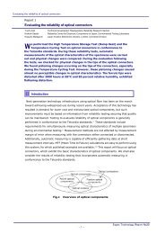
Report 1<br />
A Consideration of Methods for Evaluating Reliability<br />
of Electronic Parts<br />
— Concerning Methods of Continuously Evaluating Ion Migration —<br />
Hirokazu Tanaka* 1/Yuuichi Aoki* 1/Shigeharu Yamamoto* 1/Kunikazu Ishii* 2<br />
Many kinds of testing methods are being explored for use in evaluating<br />
reliability. This report examines methods of evaluating reliability of<br />
electronic parts and finding the causes of performance degradation and<br />
malfunction for which intermittent testing isn’t effective. Evaluation is made by<br />
continuously measuring insulation resistance of printed circuit boards (PCB) while<br />
applying environmental stress, thus monitoring characteristic values throughout the<br />
time these values are fluctuating.<br />
1. Introduction<br />
In evaluating reliability of electronic parts, many<br />
kinds of environmental tests are being performed depending<br />
on the measurement parameters and the perceived<br />
failure mode. In general, the test methods rely on<br />
intermittent measurements to make their evaluations. In<br />
other words, the initial measurements are compared<br />
with the post-test measurements. However, with this<br />
method it is extremely difficult to confirm failure<br />
caused by fluctuating characteristic values or to confirm<br />
equipment failure caused by a momentary drop in insulation<br />
resistance during continuous operation. Such<br />
problems typically occur in ion migration (IM).<br />
2. Test Method<br />
2-1 Specimen and Test Conditions<br />
Fig.1 shows the shape of the specimen used in this<br />
evaluation testing. The circuit pattern is made by copper<br />
plating four counter electrode patterns on a glass epoxy<br />
substrate board (Japanese Industrial Standard C 6484:<br />
GE4).<br />
Pattern<br />
width, 1mm<br />
*1 Environmental Test Technology Center<br />
*2 Measuring Control System Dept.<br />
Overlap, 5mm<br />
Pattern interval,<br />
0.25mm<br />
For this report we evaluated characteristics by continuously<br />
measuring the fluctuation of characteristic<br />
values, and we tried to capture the causes of performance<br />
degradation and malfunction by continuously<br />
measuring while applying environmental stress to PCB<br />
specimens. This report will discuss continuously measuring<br />
insulation resistance under conditions of high<br />
temperature and high humidity and the effectiveness of<br />
continuously evaluating characteristics.<br />
45mm<br />
35mm<br />
Copper-plated<br />
pattern<br />
Cathode (–) Anode (+)<br />
(a) Electrode shape (b) Shape of substrate and pattern<br />
Fig.1 Shape of specimen substrate used as base<br />
ESPEC TECHNOLOGY REPORT No.2 13
Table 1 shows the test conditions. The test confirmed<br />
the fluctuation (degradation) of insulation resistance<br />
due to different surface treatments of the PCB.<br />
Tests were prepared using the following 3 types of<br />
surface treatments for specimens.<br />
➀ Clean only<br />
➁ Coating with non-cleaning flux after cleaning<br />
➂ Solder treatment after cleaning and coating with noncleaning<br />
flux<br />
Temperature<br />
and humidity<br />
+60°C<br />
90%RH<br />
500 hours<br />
Applied<br />
voltage<br />
25 V DC<br />
2-2 Evaluation system and Measurement<br />
Conditions<br />
2-2-1 Evaluation system<br />
Fig.2 shows an external view of the IM evaluation<br />
system equipment, a system block diagram, and gives<br />
specifications.<br />
External view<br />
Table 1 Test conditions<br />
Details of surface treatments<br />
· Clean: The substrate surface was washed with alcohol<br />
(IPA) using ultrasonic cleaning, then dried.<br />
· Coating with non-cleaning flux: Resin type noncleaning<br />
flux was coated evenly on the surface, then<br />
dried for 30 minutes at +100°C.<br />
· Solder treatment: Solder dip was done for 5 seconds<br />
at +260°C in a solder bath.<br />
Substrate surface treatment<br />
➀ Clean-only<br />
➁ Coating with non-cleaning flux after cleaning<br />
➂ Solder treatment after cleaning and coating with non-cleaning flux<br />
System block diagram<br />
System controller section<br />
Uninterruptible<br />
power supply<br />
System<br />
Controller<br />
Printer<br />
GP-IB<br />
Specifications<br />
Leak current detection:<br />
to detect sudden changes in leak current due to IM progressing and contacting<br />
counter electrode. (From leak current detection to electric field<br />
stress OFF, response time: msec/point)<br />
Leak current detection range: 1 - 100mA (1mA step)<br />
Stress applied current: 3 - 100V DC (1V step)<br />
DC current measurement range: 3 pA - 100mA<br />
Resistance measurement range: 10 6 W - 3 ´ 10 13 W (when 100 V applied)<br />
Continuous testing time: Max. 9,999 hours<br />
Measurement interval: Variable (Min. 6 min.)<br />
Measurement time: 80 sec./25 points + charging time<br />
(user specified)<br />
Measurement applied voltage: 3 - 100 V DC (1 V step, stress applied<br />
voltage and individual settings possible)<br />
Number of measurement points: 25 points (Max. 300 points)<br />
System rack<br />
GP-IB<br />
Measurement<br />
controller<br />
GP-IB<br />
Intrumentation section<br />
E-BUS<br />
GP-IB adapter (PMS-CG)<br />
System control, temperature and humidity<br />
monitor, alarm control<br />
Parallel I/O<br />
Ultra high resistance<br />
measuring device<br />
6 13<br />
(10 to 10 )<br />
Power unit for<br />
stress application<br />
(3 V to 100 V, DC)<br />
(Stress OFF setting possible)<br />
Leak current<br />
detection<br />
Scanner for<br />
micro current<br />
Fig.2 IM evaluation system (Model: AMI-025-P, made by Tabai Espec)<br />
10 12<br />
10 11<br />
10 10<br />
10 9<br />
10 8<br />
10 7<br />
10 6<br />
10 5<br />
Triaxial cable<br />
Environmental test<br />
chamber options<br />
Temperature and<br />
humidity chamber,<br />
or<br />
Highly accelerated<br />
temperature and<br />
humidity stress<br />
test chamber,<br />
and others<br />
Specimen<br />
· Example of how leak current detection works<br />
: Cyclical measurement<br />
: Leak current detection<br />
Leak currnt<br />
detection level<br />
setting<br />
10 20 30 40 50 60 70 80 Hours (h)<br />
14 ESPEC TECHNOLOGY REPORT No.2
The system used for this test consists of steadily applying<br />
voltage to the specimen, changing over the scanner<br />
at fixed intervals, and measuring the insulation<br />
resistance value of each specimen. Double shielding<br />
wire with guard attached was used for wiring connections<br />
to each specimen, and external noise and test<br />
chamber noise were suppressed to the smallest amount<br />
possible.<br />
2-2-2 Measurement conditions<br />
Table 2 shows the measurement conditions. To measure<br />
the resistance value of the specimen in a stable state,<br />
measurement charging time was set at 30 seconds. Also,<br />
to avoid having high voltage destroy migration that had<br />
already occurred, measurement voltage was the same<br />
value as applied voltage.<br />
Table 2 Measurement conditions<br />
Measurement voltage (charging time) 25 V DC (30 sec.)<br />
Insulation resistance measurement interval Every 6 min.<br />
· Leak current detection is continuously monitored separately from the<br />
Leak current detection<br />
insulation resistance measurement system.<br />
· Detection is set to max. 10 6 .<br />
3. Test Results<br />
Fig.3 shows test results.<br />
➀ Clean-only specimens: At the initial test step the insulation<br />
resistance value dropped while repeatedly recovering<br />
and dropping. At 230 hours it fell below 10 6 W and<br />
short circuited.<br />
➁ Specimens coated with non-cleaning flux: From the initial<br />
step the insulation resistance stabilized at about<br />
10 12 W.<br />
➂ Solder-treated specimens: Short circuiting occurred at<br />
max. 10 6 W at 360 hours.<br />
Resistance ( )<br />
1.0E15<br />
1.0E14<br />
1.0E13<br />
1.0E12<br />
1.0E11<br />
1.0E10<br />
1.0E09<br />
1.0E08<br />
1.0E07<br />
1.0E06<br />
0 50 100 150 200 250 300 350 400 450 500<br />
Time (h)<br />
When removing the above specimens during the test<br />
and measuring at normal temperature, we were unable<br />
to observe leak current in ➀ or ➂. The observation<br />
could not be made because continuous monitoring was<br />
not being made, and the characteristics had returned to<br />
their original values. This prevented our properly measuring<br />
the time that failure occurred.<br />
2 Coated with non-cleaning flux<br />
1 Clean-only<br />
3 Solder-treated<br />
Fig.3 Fluctuations in specimen insulation resistance<br />
Main capabilities required of the evaluation<br />
system:<br />
1. To measure minute leak current, the system must<br />
be able to suppress external noise and system internal<br />
leak current, and be able to measure high resistance.<br />
2. In response to such occurrences as IM, the system<br />
must be able to confirm fluctuations in insulation<br />
resistance and in intermittent short circuiting.<br />
3. The system must be able to instantly detect the occurrence<br />
of leak current below the uniform resistance<br />
value.<br />
4. When leak current is detected, the system must be<br />
able to stop voltage application to that specimen<br />
and preserve occurrence conditions.<br />
ESPEC TECHNOLOGY REPORT No.2 15
Photo.1 shows the observed results.<br />
➀ Clean-only specimens: Complete short circuiting has<br />
not occurred in these, but small foreign particles have<br />
become attached. — Photo.1 (a)<br />
➁ Specimens coated with non-cleaning flux: We were unable<br />
to confirm IM.<br />
➂ Solder-treated specimens: The substrate copper has<br />
leaked out, and short circuiting has been caused by IM.<br />
— Photo.1 (b)<br />
4. Discussion<br />
(a) Clean-only specimen<br />
Foreign particle<br />
The results show that complete migration could be<br />
observed only in the solder-treated specimens. Also, the<br />
clean-only specimens repeatedly made a step-like drop<br />
in insulation resistance then recovered.<br />
To confirm what caused these results, two specimens<br />
were analyzed in a scanning electron microscope (SEM)<br />
and an energy-dispersive x-ray micro analyzer.<br />
— Photo.2, Fig.4<br />
Carbon (C) and copper (Cu) were detected from the<br />
clean-only specimen by elemental analysis. Accordingly,<br />
we can assume that moisture absorption by foreign<br />
particles adhering to the surface of the substrate<br />
causes ions (e.g., copper ions) to move along the substrate<br />
surface, subsequently causing short circuiting and<br />
other phenomena. — Fig.4 (a)<br />
Observation of SEM images confirmed the occurrence<br />
of migration from the flux crack area in the soldertreated<br />
specimens. Also, the composition was tin (Sn),<br />
lead (Pb), and copper (Cu). — Photo.2 (b)<br />
Photo. 1 Microscopic image of specimen (30´)<br />
Cathode (–)<br />
Point A<br />
Foreign particle<br />
Cathode (–)<br />
Migration<br />
(b) Solder-treated specimen<br />
(a) Clean-only specimen<br />
Anode (+)<br />
Point B Anode (+)<br />
(b) Solder-treated specimen<br />
Photo. 2 SEM specimen images (200´)<br />
16 ESPEC TECHNOLOGY REPORT No.2
X-ray<br />
X-ray<br />
strength<br />
(count) C<br />
Point A<br />
strength<br />
(count)<br />
O<br />
Cu<br />
Pt<br />
From this we can assume that cracks occurred in the<br />
region of the boundary between solder and flux, and that<br />
the solder and the substrate copper melted and migrated.<br />
With the specimens coated with non-cleaning flux,<br />
we can assume that the effectiveness of the moisture resistance<br />
of the flux prevented moisture absorption under<br />
high temperature and high humidity, thus preventing<br />
migration. When evaluating the reliability of specimens<br />
in this manner, we can conclude that the dew condensation<br />
cycle test is very effective in that it can repeatedly<br />
apply high temperature cyclical stress and dew condensation<br />
stress simultaneously.<br />
As described above, temporary recovery occurs from<br />
the drop in insulation resistance, so intermittently measuring<br />
under long-period conditions of high temperature<br />
and high humidity cannot accurately catch degradation<br />
or the time that insulation is lowered (time till failure).<br />
However, continuously measuring insulation resistance<br />
makes it possible to improve testing precision by accurately<br />
catching degradation and the time that insulation<br />
is lowered.<br />
[Reference Bibliography]<br />
1) Philippe Dumounlin, Jean-Paul Seurin, Pierre Marce:<br />
“Metal Migration”, IEEE Transaction Hybrid, 1982, pp 479-486<br />
2) M.Murao, S.Shiota:<br />
“Possible Causes”, ISTFA 18th inter, 1992, pp 95-99<br />
Pb<br />
Cu<br />
Pt<br />
5. Conclusion<br />
Continuously measuring while applying environmental<br />
stress was confirmed to be an effective method<br />
for evaluating reliability to find the causes of degradation<br />
and failure due to fluctuating characteristic values.<br />
By continuously measuring insulation resistance, we<br />
were able to confirm temporary drops in insulation resistance<br />
and subsequent recovery that could not be<br />
measured with intermittent measurement. We were also<br />
able to continuously confirm the movement toward<br />
short circuiting.<br />
We can assume that these phenomena also occur in<br />
the field. Because of this, we can assume that in such<br />
cases as IM, the current method of life prediction by intermittent<br />
measuring during long-period high-temperature,<br />
high-humidity conditions cannot provide effective<br />
test evaluation. Therefore, to accurately predict product<br />
life in this type of case, we can postulate that it is necessary<br />
to continuously measure insulation resistance and<br />
accurately catch the time taken to reach the level in<br />
which failure is determined.<br />
3) Simon J.Krumblin:<br />
“Tutorial: Electrolytic”, IEEE, 1995, pp 539-549<br />
Point B<br />
0.000 5.120 10.230<br />
0.000 5.120 10.230<br />
Energy (keV) Energy (keV)<br />
(a) Clean-only specimen<br />
C O Cu<br />
Pt<br />
Pb<br />
Sn<br />
(b) Solder-treated specimen<br />
Fig.4 Elemental analysis results from X-ray spectrum measurement (Platinum (Pt) detection is from SEM)<br />
4) Aoki Yuuichi:<br />
“Evaluation Method” (Part 1), (Part 2), ESPEC Technology Report,<br />
1996, pp 16-27<br />
ESPEC TECHNOLOGY REPORT No.2 17<br />
Cu<br />
Pt
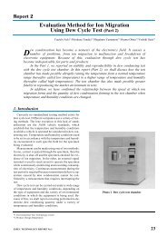
Report 2<br />
Explanation of International Standard IEC 68-2-66<br />
Environmental testing – Part 2:Test methods – Test Cx: Damp heat, steady state<br />
(unsaturated pressurized vapour)<br />
Toshio Yamamoto*<br />
This standard was established and published in June, 1994. Deliberations on the<br />
contents were inaugurated by working group 4 of subcommittee 50B, and about<br />
5 years have passed since concrete activities were begun.<br />
The Japanese Industrial Standard, JIS, conforms to the ISO and the IEC. This<br />
standard is soon to be adopted by JIS, and it is expected to be put to practical application<br />
in business contracts as one method of environmental testing in such areas as electrical<br />
and electronics parts and products.<br />
1. Introduction<br />
As a formal member of WG4, Tabai Espec was<br />
deeply involved in creating the original draft together<br />
with members from other countries. Tabai Espec’s contribution<br />
was based on its results of developing testing<br />
equipment using test conditions and developing and improving<br />
test software. Most of the essential points and<br />
the details were proposed by the Japanese participants.<br />
The IEC 68-2-66 test conditions have been formally<br />
published by IEC and have been internationally recognized.<br />
The Highly Accelerated temperature and humidity<br />
Stress Test (HAST) chamber of Tabai Espec has also<br />
gained international standing.<br />
Table 1 Composition of standards<br />
Main article Attached document<br />
1. Appropriate Range A. Steam Pressure Table †<br />
2. Summary of Test<br />
B. Physical Meaning of<br />
the Test<br />
3. Test Equipment<br />
C. Definition of Humidity<br />
4. Test Severity<br />
D. Test Equipment and<br />
Handling<br />
5. Initial Measurement<br />
6. Test<br />
7. Intermediate measurement<br />
8. Recovery<br />
9. Final Measurement<br />
10. Information to be given in the relevant specification<br />
sheets<br />
† Attached document (Annex) A, the Steam Pressure Table, forms a<br />
portion of the main article.<br />
* Environmental Test Technology Center<br />
2. Summary of Test Method<br />
2-1 Appropriate Range<br />
· The subjects of testing are small electrical and electronics<br />
devices, mainly non-hermetically sealed devices,<br />
particularly those sealed in plastic.<br />
· Durability against degradation from temperature and<br />
humidity is evaluated using acceleration methods.<br />
· External effects such as corrosion and distortion of<br />
test specimens are not considered in this test.<br />
As noted above, the reasons for limiting the type of<br />
specimens that are subject to evaluation are as follows.<br />
Materials such as plastics can be more economically<br />
sealed than metals and ceramics, which require more<br />
complicated sealing techniques. However, plastics are<br />
extremely porous in the micro range, meaning they are<br />
permeable and so extremely poor at sealing out moisture.<br />
Despite this, most electric and electronic parts are<br />
currently sealed in plastic, and plastics are used in sealing<br />
extremely vital functional parts such as IC.<br />
We would like to make very clear that the subject of<br />
evaluation is the sealed internal section of the specimen,<br />
and that distortion of the external section is not considered.<br />
18 ESPEC TECHNOLOGY REPORT No.2
2-2 Summary of Test<br />
· Normally the test is performed by applying bias.<br />
· Conditions for extremely accelerated tests are selected<br />
after first confirming that the conditions correlate<br />
to the failure mode.<br />
· Great care is taken with the highest rated temperature<br />
of parts and the critical temperature of sealing material<br />
(e.g., the plastic to glass transition temperature).<br />
Thorough consideration must be made in advance to<br />
plan acceleration in a harsh environment of high temperature<br />
and high humidity, as well as high pressure.<br />
2-3 Test Equipment<br />
2-3-1 Test chamber<br />
· The chamber must create the prescribed test environment,<br />
and must be able to maintain the environment<br />
during the test process.<br />
· Condensation must not drip onto specimens.<br />
· Material used in constructing the chamber must not<br />
contaminate the humidifying water or cause specimens<br />
to corrode.<br />
· The temperature and humidity distribution under test<br />
conditions inside the chamber at the optional locations<br />
for specimens must remain within ±2°C and<br />
±5%RH. The specimens must be arranged so that<br />
they don’t noticeably impede currents of steam.<br />
Steam must not condense on the surface of the specimens.<br />
2-3-2 Humidifying water<br />
· Distilled water or deionized water must be used.<br />
· At 23°C the water must not go below 0.5MWcm.<br />
· The PH at 23°C must remain within 6.0 – 7.2.<br />
The current Tabai Espec HAST chamber fulfills all<br />
of the above conditions.<br />
2-4 Test Severity<br />
Severity is one condition of the test, and a condition<br />
that draws considerable interest from users. This value<br />
drew a number of suggestions from participants of various<br />
countries during the discussions, resulting in the<br />
strong insistence of the Japanese participants being<br />
adopted. In particular, “exposure time (duration)” is the<br />
same as the value in IEC Pub.749 amendment 1 (1991-<br />
11) (standards for semiconductor devices). In other<br />
words, the character of this standards draft indicates a<br />
strong consciousness of the fact that the semiconductors<br />
are sealed in plastic.<br />
Severity<br />
The exposure time in the Table 2 has values that double<br />
for each temperature. The phenomena that are the<br />
subject of this test are essentially results of chemical reactions,<br />
and are interpreted using Arrhenius’ laws of reactions<br />
and theory of rate of chemical reactions.<br />
Table 2 Severity<br />
Conditions Severity<br />
Temperature<br />
°C (1)<br />
Relative<br />
humidity<br />
%RH (2)<br />
Exposure time (h) (3)<br />
I II III<br />
A 110 85 96 192 408<br />
B 120 85 48 96 192<br />
C 130 85 24 48 96<br />
(1) ±2°C (in working space)<br />
(2) ±5%RH<br />
(3) 0, +2h<br />
Other Items<br />
· This test method is a steady state test, and is not cyclical.<br />
· Tests requiring restarting are not recommended, but<br />
when a test requires a time longer than that given in<br />
column III of Table 2, the test must be restarted<br />
within 96 hours after the ramp-down period of the<br />
previous test.<br />
· Exposure time in Table 2 doesn’t include such time<br />
as ramp-up, ramp-down, or preparation.<br />
2-5 Initial Measurements<br />
· Each specimen must be visually examined before the<br />
test and inspected to insure that it conforms to prescribed<br />
characteristics such as dimensions and functions.<br />
ESPEC TECHNOLOGY REPORT No.2 19
2-6 Test<br />
· First, a specimen with a room temperature environment<br />
must be installed in a test chamber with the<br />
same temperature.<br />
· The installed specimen must not be directly exposed<br />
to radiation from the chamber walls or the heater.<br />
When using an appropriate mounting structure for installation,<br />
both the thermal capacity of the structure<br />
and the heat conducted to the specimen by the structure<br />
must be small. The structure must not discharge<br />
contaminants causing corrosion or degradation of the<br />
specimen.<br />
· Bias voltage must be applied based on the relevant individual<br />
specifications of the specimen.<br />
· Fig.1 shows the test cycle, the processes from the beginning<br />
to the end of the test.<br />
Temperature,<br />
Humidity,<br />
Pressure<br />
Atmospheric<br />
pressure<br />
This diagram is not included in IEC 68-2-66 publication.<br />
Settings<br />
Temperature<br />
Humidity<br />
Pressure<br />
Max. 1.5h Exposure time based on rating<br />
Applied bias<br />
1–4h Recovery process<br />
Time<br />
2–24h<br />
2-7 Intermediate Measurements<br />
· Electrical and physical inspections may be performed<br />
during the exposure period if products have<br />
relevant individually rated specifications. However,<br />
such actions must not disturb the test environment.<br />
· The specimen must not be removed from the chamber<br />
when measuring.<br />
2-8 Recovery<br />
· After a specimen has been removed from the chamber,<br />
it enters the recovery process in which various<br />
measurements and functional tests are performed.<br />
These actions must be performed at atmospheric<br />
pressure at a minimum of 2 hours and a maximum of<br />
twenty-four hours after the test.<br />
2-9 Final Measurements<br />
· Details of final measuring are the same as initial<br />
measuring.<br />
Fig.1 Test Processes<br />
Conditions during ramp-up<br />
· Tests in which the exposure time exceeds 48 hours can be<br />
permitted a ramp-up time of 3 hours maximum.<br />
· Relative humidity must not exceed 85%RH.<br />
· Air remaining in the chamber will be discharged from the<br />
chamber by steam during ramp-up.<br />
Conditions during ramp-down<br />
· Relative humidity must not exceed 85%RH.<br />
· As a rule, specimens must cool down naturally.<br />
· When pressure is reduced using forced opening equipment,<br />
pressure must not be lowered suddenly.<br />
· Pressure must never go below atmospheric pressure.<br />
2-10 Information to be given in the relevant<br />
specification sheets<br />
When product characteristics must be tested, details<br />
for the following items must be concretely specified.<br />
a. Differences from Table 2 specifications (compulsory<br />
item)<br />
b. Details of initial measurements (compulsory item)<br />
c. Mounting structures<br />
d. Bias voltage (when necessary)<br />
e. Intermediate measurements<br />
f. Final measurements (compulsory item)<br />
Annex A<br />
Steam Table from 100°C to 170°C<br />
Annex B<br />
Physical Meaning of the Test<br />
· The acceleration is due to the difference in the water<br />
vapor pressure between the inside of the specimen<br />
and the test environment.<br />
· A historical background is given explaining such factors<br />
as how this test was developed as an accelerated<br />
test method for testing corrosion of aluminum circuits<br />
on integrated circuits sealed in plastic and other<br />
semiconductor devices.<br />
20 ESPEC TECHNOLOGY REPORT No.2
Annex C<br />
Items Related to a Definition of Humidity<br />
· No method of directly measuring humidity has yet<br />
been established for the temperature and humidity<br />
range used.<br />
· Humidity must be defined according to theoretical<br />
evaluation of a practical method of measurement. In<br />
other words, it is permissible to use any measuring<br />
method that is possible if it is within a theoretically<br />
acceptable deviation.<br />
· Remaining air is discharged during the ramp-up process,<br />
but because of dissolved gas in the humidifying<br />
water and any gas discharged from the specimens, the<br />
interior of the chamber can’t be termed a perfect vapor<br />
environment. However, it is difficult to believe<br />
that such a minute quantity of gas has much influence<br />
on the results of the test, so the interior of the chamber<br />
hypothetically fulfills the condition of having<br />
only steam.<br />
· There are three methods by which humidity may be<br />
measured: the temperature method (measuring the<br />
temperature inside the working space and the temperature<br />
of the humidifying water, or the temperature<br />
immediately above the humidifying water), the<br />
wet/dry bulb method, and the dew point method.<br />
Any of these methods of measuring can provide essential<br />
control and be used for monitoring, but the<br />
dew point method is difficult to use with current technology.<br />
DO<br />
PV<br />
PV Pressure vessel<br />
DO Door<br />
WS Working space<br />
PV1 Test chamber (pressure<br />
vessel for working space)<br />
PV2 Steam generator<br />
(pressure vessel for<br />
humidifying water<br />
reservoir)<br />
Single vessel (Tabai type)<br />
WA<br />
PG SV<br />
WS<br />
WA Humidifying water<br />
PG Pressure gage<br />
SV Safety valve<br />
AV Air release valve<br />
S1 Temperature sensor for<br />
steam<br />
S2 Temperature sensor for<br />
humidifying water<br />
F Fan<br />
Concrete explanations, which had not been described<br />
in any traditional IEC Publication Standard, are contained<br />
in the above attached documents, and most of the<br />
Japanese suggestions have been included.<br />
[Reference Bibliography]<br />
1) Environmental testing-Part2: Test methods-Test Cx: Damp heat,<br />
steady state (unsaturated pressurized vapour), IEC International<br />
Standard, 1994<br />
S1<br />
F<br />
HW S2<br />
HM<br />
AV<br />
Annex D<br />
Test Equipment and Handling<br />
· The test equipment is limited to two types, the single<br />
vessel (Tabai type) and dual vessel types. The construction<br />
of those two types is shown in Fig.2.<br />
· The steam current must be kept within 0.5 m/sec<br />
maximum, the range of a natural convection current.<br />
· Materials causing corrosion or degradation must not<br />
be used inside the chamber. The applied bias voltage<br />
will “work effectively” for this test, meaning it will<br />
accelerate corrosion. That bias voltage and time of<br />
application must be adjusted, however, because an<br />
opposing surface may be adversely affected, e.g., by<br />
preventing moisture absorption through self-heating.<br />
For example, the specimen surface temperature must<br />
not rise more than 2°C above ambient temperature, so<br />
when self-heating is severe, the time of application<br />
ratio may be set to ON:OFF = 1:3.<br />
· Lubrication should be done periodically using a soft<br />
brush with laboratory detergent in distilled water or<br />
de-ionized water.<br />
· As a rule, the test should be completed with the specimen<br />
left untouched after delivery of the specimen has<br />
been received.<br />
· Diagram showing an outline of representative test<br />
equipment construction is included.<br />
DO<br />
PV1<br />
HM Heater for moisture<br />
HW Heater for humidifying<br />
water<br />
Fig.2 Test equipment construction<br />
PG<br />
Dual vessel<br />
WS<br />
HM<br />
S1<br />
SV<br />
AV<br />
PV2 S2<br />
ESPEC TECHNOLOGY REPORT No.2 21<br />
WA<br />
HW
Topics<br />
1. Introduction<br />
News of changes in the earth’s environment and the<br />
increase in global population have brought agriculture<br />
to the forefront in vital social issues, both from the aspect<br />
of protecting the environment as well as in regard<br />
to the food problem.<br />
2. Our Agribusiness<br />
At Tabai Espec, the development of our agribusiness<br />
can be broadly classified into two themes, or business<br />
units. First, we offer “plant factories”, which supersede<br />
conventional agriculture with our systems for producing<br />
crops such as vegetables under a high degree of environmental<br />
control. Also, we offer “plant related test research<br />
equipment”, our research equipment for the test<br />
research that forms a basis for this agricultural production.<br />
[Concepts]<br />
We offer environments for<br />
“Food” and “Protecting the<br />
Global Environment”<br />
Agribusiness<br />
2-1 Plant Factories<br />
The “plant factories” system is extremely broad in<br />
scope, but in general can be described as “an institute<br />
for the industrial production of plants”. The main features<br />
of the plant factories are as follows.<br />
1. Agricultural crop production can be scheduled<br />
year round.<br />
2. Plants can be efficiently produced even in small<br />
spaces.<br />
3. Safe crops can be produced without using agricultural<br />
chemicals.<br />
4. Crops can be standardized and high quality items<br />
can be produced.<br />
5. Work can be automated and made less labor-intensive.<br />
Agribusiness<br />
As we face the 21st century, here at Tabai Espec we<br />
have taken the crucial social issues of “Food” and “Protecting<br />
the Environment” as our themes. We are addressing<br />
these issues by striving to create a new<br />
“agribusiness” based on the environment creation technology<br />
that we have fostered.<br />
Complete control plant factory<br />
Supplementary lighting plant factory<br />
Plant factories Sunlight-utilizing plant factory<br />
Seedling plant factory<br />
Mushroom factories, bean sprout factories,<br />
other sprout factories...<br />
Phyto-tron (standard, large)<br />
Growth Chamber (artificial lighting)<br />
Plant test research<br />
Growth Cabinet<br />
equipments<br />
Green House<br />
Various control systems and sensors<br />
Fig. 1 Development of our Agribusiness<br />
The most significant way in which the plant factories<br />
differ from conventional agriculture is that “crop production<br />
can be scheduled year round”. Agricultural productivity<br />
is relatively low compared to other kinds of<br />
production as in industry, and in addition, stable production<br />
has been difficult to obtain due to the influence<br />
of the seasons and the weather. In response to these factors,<br />
our plant factories make it possible to artificially<br />
control the cultivation environment.<br />
These plant factories can also be classified into a<br />
number of different types, but the “complete control<br />
plant factory” is most often regarded as a representative<br />
“plant factory”. In a narrow sense, this type has many<br />
factory-like representative features, including completely<br />
blocking sunlight from the interior of the fac-<br />
22 ESPEC TECHNOLOGY REPORT No.2
tory, using artificial light, and cultivating plants under<br />
complete control of weather environment conditions<br />
such as temperature and humidity. Next comes the “supplementary<br />
lighting plant factory”, which actively introduces<br />
sunlight and supplements with artificial lighting<br />
as necessary while also controlling weather environment<br />
conditions. There is also another type of “sunlight-utilizing<br />
plant factory” that does not use<br />
supplementary lighting. In addition, we have equipment<br />
qualifying as plant factories in a broader sense, such as<br />
the “seedling plant factory”, which produces seedlings<br />
using biotechnology and cellular formed seedlings, and<br />
we have plant factories for mushrooms, for bean<br />
sprouts, and for other sprouts.<br />
3. Environmental Control Technology in Agriculture<br />
An environment for cultivating plants can be greatly<br />
influenced by such factors as temperature, humidity,<br />
wind, the concentration of carbon dioxide, and the underground<br />
part of the environment (e.g., the composition<br />
of the soil or the axil). Not only does the most<br />
appropriate environment vary according to the complicated<br />
reciprocal relationship among these factors, but it<br />
also varies according to other factors such as the type<br />
and variety of plants being cultivated. Plant production<br />
includes aspects that are more difficult than producing<br />
industrial products.<br />
Lighting<br />
Sunlight<br />
Artificial<br />
lighting<br />
Temperature<br />
Humidity<br />
Carbon<br />
dioxide<br />
concentration<br />
Technology to filter sunlight, selectively<br />
admitting light effective for photosynthesis<br />
while blocking undesirable rays and radiant<br />
heat.<br />
Technology related to artificial lighting to<br />
obtain the quantity and quality of light that<br />
can be substituted for sunlight. One<br />
particularly important problem in a closed<br />
space is how to handle heat generated by<br />
lamps.<br />
Technology to control the temperature to<br />
create an environment suitable for growing<br />
plants. Energy-saving technology to control<br />
temperature, as being economical is very<br />
important in production.<br />
Technology to control humidity to create an<br />
environment suitable for plant evaporation<br />
functions. Also strongly affects<br />
photosynthesis.<br />
Technology to control the concentration of<br />
carbon dioxide. By raising the<br />
concentration of carbon dioxide, it is<br />
possible to raise the capacity for<br />
photosynthesis.<br />
2-2 Plant Test Research Equipment<br />
In this field, we provide a great variety of systems<br />
and equipment to support plant-related test research in<br />
universities as well as in a wide variety of test research<br />
laboratories. This equipment and these systems are used<br />
for a wide range of applications, such as developing new<br />
hybrids for agricultural production, research on disease<br />
resistance and environmental features, research on agricultural<br />
chemicals, and research on medical drugs.<br />
In this field, our company provides a wide range of<br />
products that control the environment in such areas as<br />
temperature and humidity and are used for all kinds of<br />
test research. Our line of products includes such equipment<br />
as the Phyto-tron, the Growth Chamber, the<br />
Growth Cabinet, and the Green House, as well as all<br />
types of sensors and control systems.<br />
However, producing agricultural crops goes beyond<br />
these factors. We cannot ignore the extremely high<br />
value of know-how stored up from long years of observing<br />
results. The technological development required to<br />
quantify and qualify these factors is a technological<br />
problem facing both plant factories and the field of plant<br />
test research, but recently computerization has been introduced<br />
into the field of agriculture and is bringing<br />
rapid development. The various research sites are vigorously<br />
promoting expert systems for cultivation and<br />
greenhouse environment control, and progress is being<br />
made in putting this knowledge to practical use.<br />
Table 1 Principal environmental control technology in agribusiness<br />
Wind<br />
(wind speed)<br />
Soil (axil)<br />
temperature<br />
Soil (axil)<br />
composition<br />
Cultivation<br />
technology<br />
Technology to control wind speed. Wind<br />
promotes proper evaporation and keeps<br />
leaves cooler. In general, plants prefer an<br />
environment with a mild breeze (max. 0.5<br />
m/s).<br />
Technology to control the environment of<br />
the underground section (root environment<br />
section). This part strongly influences plant<br />
cultivation, and is very effective when the<br />
soil (axil) is heated if the above-ground<br />
temperature is low, or cooled if the aboveground<br />
temperature is high.<br />
Technology to control such factors as pH<br />
and nutrient conditions most suitable for<br />
plant growth, such as N (nitrogen), K<br />
(potassium), and P (phosphorus).<br />
Composition of the soil and of the axil has<br />
vital influence on plant cultivation.<br />
Technology directly for plant cultivation.<br />
Computers are being used to develop<br />
technology to find a means for acquiring<br />
this know-how and then to find a means to<br />
put it to practical use.<br />
ESPEC TECHNOLOGY REPORT No.2 23
4. Our Main Agribusiness Products (Systems)<br />
4-1 Plant Factories<br />
(1) Container Plant Factory<br />
With the transportable plant factory units, it is possible<br />
to immediately cultivate plants anywhere that water<br />
and electricity connections are available. Since the site<br />
can’t be selected, the units can be used for various applications,<br />
such as on a marine vessel, at the north or south<br />
pole, or in the back yard of a restaurant. Development<br />
concepts and economic feasibility are being evaluated.<br />
— Photo. 1<br />
(2) Complete Control (Artificial Lighting) Plant<br />
Factory and Supplementary Lighting Plant<br />
Factory<br />
Facilities for producing greens such as lettuce and<br />
spinach as well as other types of vegetables such as tomatoes.<br />
Plants are cultivated in a controlled environment,<br />
and speed of growth and production efficiency are<br />
extremely high.<br />
In complete control plant factory there is little influence<br />
from the natural environment. While this makes it<br />
possible to schedule production year round, it also has<br />
the defect of fairly high operating expenses, especially<br />
for electric utilities.<br />
In the supplementary lighting plant factory, there is<br />
some influence from the natural environment, bringing<br />
down the initial cost as well as the operating expenses,<br />
so they can be made on a larger scale.<br />
In addition, we are building systems for improving<br />
productivity by promoting the development of such<br />
equipment as a conveyance spacing device that automatically<br />
controls the intervals between the plants, for<br />
complete control (artificial lighting) plant factory and<br />
supplementary lighting plant factory.<br />
Photo. 1 Equipment for experiments with container cultivation<br />
Equipment for mixing axil<br />
(inside container)<br />
24 ESPEC TECHNOLOGY REPORT No.2
4-2 Plant-Related Test Research Equipment<br />
(1) Phyto-tron (Standard, Large)<br />
Test research equipment for plants has been established<br />
outdoors, and controls such factors as temperature,<br />
humidity, and carbon dioxide concentration. An<br />
infrared ray screening filter, independently developed<br />
by our company, is used on the surface of the glass, providing<br />
a savings in energy. This filter is a superb material<br />
that selectively admits light effective for plant<br />
photosynthesis and reflects heat rays from the infra-red<br />
zone that cause air conditioning load. We also provide<br />
optional equipment such as a soil temperature bath and<br />
equipment to control the length of daylight.<br />
We offer two types of Phyto-tron, the factory-assembled<br />
chamber (standard) and the large model, assembled<br />
on site. — Photo. 2<br />
(2) Growth Chamber<br />
The Growth Chamber is a panel-assembled chamber<br />
that uses artificial lighting and controls factors such as<br />
temperature, humidity, and carbon dioxide. The equipment<br />
can artificially recreate all aspects of the plant cultivation<br />
environment. In particular, although heat from<br />
the lamps has an adverse effect on plant growth when<br />
obtaining high illumination intensity, the infrared ray<br />
screening filter, used to avoid this heat generation, effectively<br />
keeps leaves cooler.<br />
(3) Green House<br />
The Green House is for plant test research and maintains<br />
a high degree of control of the interior environment.<br />
The glass uses an infrared ray screening filter that<br />
saves energy, and the environment is computer controlled.<br />
— Photo. 3<br />
Photo. 2 A large Phyto-tron<br />
Photo. 3 Interior of a Green House<br />
ESPEC TECHNOLOGY REPORT No.2 25
technology report<br />
ETRE002<br />
Pub. Date:<br />
Publisher:<br />
November 1, 1996 (biannual)<br />
3-5-6 Tenjinbashi, Kita-ku, Osaka 530, Japan<br />
Please direct inquiries regarding this publication to...<br />
Office of the editor, “ESPEC Technology Report”,<br />
TABAI ESPEC CORP.<br />
Phone: (81) 6-358-4785 Fax: (81) 6-358-4786<br />
Copying or reproducing articles from this magazine in any form is prohibited.<br />
Head Office (JAPAN)<br />
3-5-6, Tenjinbashi, Kita-ku, Osaka 530, Japan<br />
Phone: (81) 6-358-4741 Fax: (81) 6-358-5500<br />
Telex: 05233629 TBI J<br />
Kuala Lumpur Representative Office (MALAYSIA)<br />
Temp Girl Business Center 4th. Floor<br />
Secondary Tower Block Wisma MCIS, Jalan Barat<br />
46700 Petaling Jaya, Selangor, Malaysia<br />
Phone: (60) 3-7544277 Fax: (60) 3-7544290<br />
(U.S.A.)<br />
425 Gordon Industrial Court, S.W.<br />
Grand Rapids, MI 49509, U.S.A.<br />
Phone: (1) 616-878-0270 Fax: (1) 616-878-0280<br />
SHANGHAI ESPEC<br />
ENVIRONMENTAL EQUIPMENT CORP. (CHINA)<br />
Ha-mi Road 166 Shanghai, China<br />
Phone Fax: (86) 21-62748060<br />
GUANGZHOU ESPEC<br />
ENVIRONMENTAL EQUIPMENT CO., LTD.<br />
(CHINA)<br />
1 Zhu Si Gang, Dong Guan Zhuang Road,<br />
Guangzhou, China<br />
Phone Fax: (86) 20-772-5042<br />
(JAPAN)<br />
23-12, Taimahigashimachi, Neyagawa-shi,<br />
Osaka 572, Japan<br />
Phone: (81) 720-34-1191 Fax: (81) 720-34-7755<br />
ESPEC TECHNOLOGY REPORT No. 2