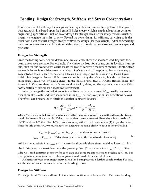
Bending: Design for Strength, Stiffness and Stress Concentrations
Bending: Design for Strength, Stiffness and Stress Concentrations
Bending: Design for Strength, Stiffness and Stress Concentrations

You also want an ePaper? Increase the reach of your titles
YUMPU automatically turns print PDFs into web optimized ePapers that Google loves.
<strong>Bending</strong>: <strong>Design</strong> <strong>for</strong> <strong>Strength</strong>, <strong>Stiffness</strong> <strong>and</strong> <strong>Stress</strong> <strong>Concentrations</strong><br />
This overview of the theory <strong>for</strong> design <strong>for</strong> bending of beams is meant to supplement that given in<br />
your textbook. It is based upon the Bernoulli Euler theory which is applicable to most common<br />
engineering applications. First we cover design <strong>for</strong> strength because <strong>for</strong> safety reasons structural<br />
integrity is engineering’s first priority. Second we cover design <strong>for</strong> stiffness, but doing so in this<br />
order does not mean that strength always controls the design (see the example). After commenting<br />
on stress concentrations <strong>and</strong> limitations at this level of knowledge, we close with an example <strong>and</strong><br />
problems.<br />
<strong>Design</strong> <strong>for</strong> <strong>Strength</strong><br />
Once the loading scenarios are determined, we can draw shear <strong>and</strong> moment load diagrams <strong>for</strong> a<br />
beam under each scenario. For example, if we know the load <strong>for</strong> a beam, but its location is uncertain,<br />
then <strong>for</strong> one scenario we would locate the load to achieve a maximum moment; <strong>for</strong> the other<br />
we would locate it to achieve maximum shear. Let’s say a simply-supported beam is to carry a<br />
concentrated <strong>for</strong>ce P, then <strong>for</strong> scenario 1 locate P at midspan <strong>and</strong> <strong>for</strong> scenario 2, locate P just<br />
inside either support. Further, if the cross section is rectangular of area A, then the maximum<br />
shear stress equals P/A (by simple shear!) <strong>for</strong> Scenario 2 rather than 3P/4A (by flexural shear) <strong>for</strong><br />
Scenario 1. Can you show both of these results? And by doing so, thereby convince yourself that<br />
consideration of critical load scenarios is important.<br />
In beam design the normal stress obtained from maximum moment Mmax usually dominates<br />
over shear stress obtained from maximum shear Vmax (but <strong>for</strong> exceptions, see limitations below).<br />
There<strong>for</strong>e, our first choice to obtain the section geometry is to use<br />
where S is the so-called section modulus, c is the maximum value of y <strong>and</strong> the allowable stress<br />
would be known. For example, if the cross section is rectangular of dimensions b × h so that I =<br />
bh3 /12 <strong>and</strong> c = h/2, then S = bh2 σ<br />
/6. Hence knowing either b or h, we can use (1) to get the other.<br />
Next <strong>for</strong> this geometry, we must check the shear stress using either or both of the following:<br />
My<br />
-------<br />
I<br />
M I<br />
= = -------<br />
I⁄ y<br />
⇒ S -<br />
c<br />
Mmax = = -----------σall<br />
τmax = ( VmaxQmax) ⁄ ( Itmin) , if the shear is due to flexure<br />
τmax = Vmax ⁄ A , if the shear is not due to flexure (simple shear case)<br />
<strong>and</strong> then demonstrate that τmax ≤ τall where the allowable shear stress would be known. If this<br />
check fails, then one must determine the geometry from (2) <strong>and</strong> check that σmax ≤<br />
σall . Otherwise<br />
we could compute geometry <strong>for</strong> each case <strong>and</strong> compare dimensions to reach a decision, but<br />
this approach provides a less evident argument <strong>and</strong> should be a second choice.<br />
A change in cross section geometry along the beam presents a further consideration. For this,<br />
see the section on stress concentrations in bending below.<br />
<strong>Design</strong> <strong>for</strong> <strong>Stiffness</strong><br />
To design <strong>for</strong> stiffness, an allowable kinematic condition must be specified. For beam bending,<br />
<strong>Bending</strong>: <strong>Design</strong> <strong>for</strong> <strong>Strength</strong>, <strong>Stiffness</strong> <strong>and</strong> <strong>Stress</strong> <strong>Concentrations</strong>7/6/99 1<br />
(1)<br />
(2)
this would normally be a bound upon deflection v like vmax ≤ vall. Although less likely, a maximum<br />
slope could be specified instead. Once a model with appropriate boundary conditions has<br />
been established, the maximum deflection or slope would be obtained using either double integration<br />
of the moment equation or a table <strong>for</strong> the solution. The relevant equations in sequence are<br />
where value is obtained by substituting the location of maximum deflection x into the deflection<br />
equation obtained from the differential equation in (3). This is illustrated in the example below.<br />
<strong>Stress</strong> Concentration Equations<br />
<strong>Stress</strong> concentrations in bending arise when uni<strong>for</strong>mity of geometry is disrupted. In this case, a<br />
design problem may become iterative if initially we do not know the beam geometry required to<br />
determine the stress concentration factor. Then the design algorithm is: 1) solve the problem <strong>for</strong><br />
dimensions of a uni<strong>for</strong>m prismatic beam, 2) determine the stress concentration factor <strong>for</strong> the disruption<br />
in the uni<strong>for</strong>m beam <strong>and</strong> use it to check if allowables are violated, <strong>and</strong> 3) repeat until optimal<br />
dimensions which satisfy all requirements are found.<br />
Hibbeler (1997) provides stress concentration factors <strong>for</strong> symmetric fillets <strong>and</strong> grooves in the<br />
top <strong>and</strong> bottom of beams. Factors <strong>for</strong> geometries including holes <strong>and</strong> both one-sided <strong>and</strong> circumferential<br />
grooves under bending, torsion <strong>and</strong> axial de<strong>for</strong>mation are given using Neuber’s diagram<br />
by Ugural <strong>and</strong> Fenster (1979). But a more general <strong>and</strong> very reliable source is Roark <strong>and</strong> Young<br />
(1975). When applying <strong>for</strong>mulas from any source, it is important to note the definition of the<br />
nominal or reference stress <strong>and</strong> the stress concentration factor itself.<br />
Limitations<br />
2<br />
dv value<br />
EI 2 = Mx ( ) ⇒ EIvmax = value ⇒<br />
I ≥ -------------dx<br />
Evmax Although Bernoulli-Euler theory is very good, its application above is <strong>for</strong> elementary design of<br />
straight beams; we neither considered curved beams (Hibbeler, 1997, § 6.8) nor accounted <strong>for</strong>:<br />
1. Situations in which the shear stress in the beam is the same order of magnitude as the normal<br />
stress. This occurs if large shear loads are applied or the beam is short. Principle stresses,<br />
obtained using trans<strong>for</strong>mation equations or Mohr’s circle (see Hibbeler, § 11.2), become<br />
important, particularly in concentrations at flange-to-web junctions. Short beams do not flex<br />
much <strong>and</strong> their deflection is due mainly to shear, not moment. A beam is said to be short if its<br />
length is less than 10 times its section depth 1 . This situation is covered in advanced courses.<br />
2. Local buckling <strong>and</strong> rotational instability of beams which involves three cases: global buckling<br />
of the structure (it buckles as a unit) which is covered subsequently in these notes; local buckling<br />
which is localized failure of a compression region in a beam (e.g., waviness in a web or<br />
local kinking); <strong>and</strong> torsional or twisting instability in thin-walled members related to shear<br />
flow (Hibbeler, § 7.4, 75).<br />
Nonetheless, this methodology will carry the day in many situations, but the engineer must<br />
always be aware of hazardous or special situations <strong>and</strong> alert all involved parties.<br />
1. Definition of a short beam is due to Zhuravskii, 1821-1891, <strong>and</strong> is discussed in Gere <strong>and</strong> Timoshenko<br />
(1997).<br />
<strong>Bending</strong>: <strong>Design</strong> <strong>for</strong> <strong>Strength</strong>, <strong>Stiffness</strong> <strong>and</strong> <strong>Stress</strong> <strong>Concentrations</strong>7/6/99 2<br />
(3)
Example<br />
BD1. <strong>Design</strong> a round chinning bar to fit between a jamb<br />
32 in wide <strong>and</strong> support a 270 lb person. Client specifications<br />
are: (1) minimize weight, (2) set grip spread to 18<br />
in as shown in the figure, (3) diameter of bar to be about<br />
1 in, (4) minimize deflection <strong>and</strong> limit it to 1/2 in <strong>and</strong><br />
(5) use a factor of safety FS = 1.2.<br />
<br />
<br />
<br />
7 in 18 in<br />
<br />
<br />
135 lb 135 lb<br />
Solution:<br />
1. For minimum weight, spec #1, choose 6061-T6 aluminum tube or pipe. Properties from Hibbeler<br />
(1997): E = 10 × 10 6 psi, σ Y = 37 ksi, τ Y = 19 ksi. Divide yield stresses by factor of<br />
safety FS to get allowables ⇒ σ all = 37/1.2 = 30.83 ksi, τ all = 19/1.2 = 15.83 ksi.<br />
(NOTE: Ryerson (1987-89) gives σ Y = 37 ksi <strong>for</strong> Alclad Al 6061-T6 1 <strong>and</strong> σ Y = 40 ksi <strong>for</strong><br />
Al 6061-T6. Our use of the lower value <strong>for</strong> this material is conservative <strong>and</strong> there<strong>for</strong>e safe.)<br />
2. Prescribe the loading scenarios. The most critical load will occur if the person hangs from the<br />
bar with one h<strong>and</strong>. This is an obvious possibility <strong>and</strong> will cover the client’s spec #2. Ranked in<br />
order from the most critical (Students should show this!), the loading scenarios are:<br />
Scenario 1: Central concentrated load. Maximum moment occurs if the entire load is<br />
placed in the center of the bar. This will also generate a maximum deflection.<br />
Scenario 2: One-sided concentrated load. Significant (but unknown) simple shear occurs if<br />
the load is placed very near to either support, say the left.<br />
3. Prescribe the models <strong>for</strong> each scenario.<br />
270 lb<br />
<br />
16 in 16 in <br />
<br />
<br />
32- in<br />
Scenario 1:<br />
A B Scenario 2: A<br />
32 in<br />
B<br />
4. Freebody diagram <strong>and</strong> statics <strong>for</strong> Scenario 1<br />
Clearly FA = FB = Vmax = 135 lb<br />
270 lb<br />
Mmax @ center = (135)(16) = 2160 in lb<br />
(Note: Students should draw V-M diagrams to<br />
16 in 16 in<br />
verify these “max” values.)<br />
5. <strong>Strength</strong> design <strong>for</strong> Scenario 1:<br />
Client spec #3 ⇒ Set r0 = 1.0/2 = 0.5 in<br />
135 lb<br />
135 lb<br />
<strong>and</strong> solve <strong>for</strong> ri where these are the outer <strong>and</strong> inner radii, respectively. Using Eq. 1,<br />
M max r o<br />
4<br />
4M max r 0<br />
<br />
<br />
<br />
270 lb<br />
32 in<br />
σall = ------------------------------<br />
4 4 ⇒ ri = r0 – --------------------- = 0.365 in<br />
π( r0 – ri ) ⁄ 4<br />
πσ<br />
⇒ twall = r0 – ri =<br />
0.134 in<br />
all<br />
Check catalog (Ryerson, 1987-89) <strong>for</strong> aluminum tube with nominal size nearest to 1" OD ×<br />
.134" wall. There the largest wall thickness <strong>for</strong> 1" tube is 0.125. Too small. Looking further the<br />
1. Alclad denotes a special aluminum alloy coating on both sides of a st<strong>and</strong>ard aluminum substrate (see<br />
Ryerson).<br />
1 ⁄ 4<br />
<strong>Bending</strong>: <strong>Design</strong> <strong>for</strong> <strong>Strength</strong>, <strong>Stiffness</strong> <strong>and</strong> <strong>Stress</strong> <strong>Concentrations</strong>7/6/99 3
next size tube with commensurate wall size is 1 1/2 in OD which greatly exceeds spec #3.<br />
However, 3/4 in pipe has dimensions: 1.05" OD × 0.113" wall. Try this. Substituting<br />
r 0 = 1.05/2 = 0.525 in into the above <strong>for</strong>mula <strong>and</strong> solve <strong>for</strong> r i <strong>and</strong> wall thickness; we get:<br />
Mmaxro σall = ------------------------------<br />
4 4 ⇒ ri =<br />
π( r0 – ri ) ⁄ 4<br />
4M 4 maxr 1 ⁄ 4<br />
0<br />
r0 – --------------------- = 0.413 in ⇒ t<br />
πσ wall<br />
all<br />
= r0 – ri = 0.112 in<br />
Excellent! Choose 6061-T6 aluminum pipe: 3/4 in O.D. × 0.113 in wall (0.824 in I.D.).<br />
6. Comments on Step 5:<br />
a) For this choice of pipe: σmax = Mmaxr0 ⁄ I = 30.6 ksi < 30.8 ksi ≡ σall ⇒ Check O.K.<br />
Here we used radii <strong>for</strong> the pipe so that I π( r0 – ri ) ⁄ 4 0.037 in .<br />
b) Warning: Ryerson (1987-89) does NOT indicate a heat treatment (T-value like T6) which is<br />
important to yield strength. Heat treatment should be settled upon prior to purchase.<br />
c) Interestingly, adequately thick tubing is st<strong>and</strong>ard stock in steel, but not in aluminum.<br />
7. Check deflection; client spec. #4:<br />
4<br />
= =<br />
PL<br />
vmax where the <strong>for</strong>mula <strong>for</strong> vmax comes from double integration of the differential equation in (3) <strong>for</strong><br />
a simply supported beam under a concentrated load P applied at midspan, i.e.,<br />
3<br />
270( 32)<br />
48EI<br />
-----------<br />
3<br />
= = ----------------------------------------------- 6 = 0.498 in < 0.5 in ⇒ Spec. #4 satisfied.<br />
48( 10×10<br />
) ( 0.037)<br />
∫<br />
2<br />
dv<br />
∫EI 2<br />
dx<br />
P Px<br />
∫∫<br />
--<br />
2<br />
x -----<br />
48<br />
3L2 4x2 – ( – ) , 0 x L<br />
= = ⎛ ≤ ≤ -- ⎞<br />
⎝ 2<br />
⇒<br />
⎠<br />
EIvmax = ---------<br />
48<br />
@ x =<br />
NOTE: Alternatively we could have used the rightmost equation in (3) to arrive at the tube or<br />
pipe dimensions <strong>and</strong> in turn used the leftmost equation in (1) as a check on strength.<br />
8. Check the flexural shear stress:<br />
For a solid semi-circular section, Q πr . Then<br />
where τall = 15.8 ksi. Students should verify this equation, especially the result <strong>for</strong> Q.<br />
9. Scenario 2. Only a strength check <strong>for</strong> simple shear is necessary. The deflection <strong>and</strong> reaction at<br />
B are negligible (Can you show this?), hence a freebody diagram is obvious (see illustration of<br />
Scenario 2 above).<br />
2 ( ⁄ 2)<br />
( 4r ⁄ 3π)<br />
2r 2 = = ⁄ 3<br />
2 3 3<br />
Q Qwhole – Qhole 3<br />
--( r0 – ri ) 0.0498 in 3 VmaxQ = = = ⇒ τmax = --------------- = 173 psi<br />
It<br />
< τall ⇒ O.K.<br />
V⁄ A 270 π 1.05 2 0.824 2<br />
= = ⁄ ( – ) ⁄ 4 = 2550 psi < τall ⇒ O.K.<br />
τ max<br />
10. Decision. Choose 6061-T6 aluminum pipe: 3/4 in O.D. × 0.113 in wall. The<br />
design is tight, both max stress <strong>and</strong> deflection are more than 99% of the allowables,<br />
but the margin of safety may be increased by using 6061-T6 rather than<br />
Alclad 6061-T6 (see note in step 1).<br />
Warnings: (1) Make certain the T6 heat treatment is applied to the aluminum.<br />
(2) Both ends of the pipe should be plugged with stiff plastic or<br />
metal to prevent local buckling of the pipe wall by distributing concentrated<br />
support reactions throughout the pipe wall at each end of the bar (see the figure).<br />
<strong>Bending</strong>: <strong>Design</strong> <strong>for</strong> <strong>Strength</strong>, <strong>Stiffness</strong> <strong>and</strong> <strong>Stress</strong> <strong>Concentrations</strong>7/6/99 4<br />
4<br />
4<br />
PL 3<br />
L<br />
--<br />
2<br />
Plug<br />
Support
Problems<br />
BD2. Redo problem BD1, but use 1018 cold drawn steel tube which has a minimum yield<br />
strength of 65 ksi. Compute the final weight of your design <strong>and</strong> compare it with that <strong>for</strong> Example<br />
BD1.<br />
BD2. <strong>Design</strong> a scaffold plank to span 10 ft between simple supports such that it is 12 in wide (11<br />
1/4 in dressed) softwood <strong>and</strong> supports three 200 lb men who each occupy 18 in length of beam<br />
<strong>and</strong> together cause no more than 1/16 in deflection. Given: σ all in bending is 900 psi, E = 1.0 × 10 6<br />
psi <strong>and</strong> τ all parallel to the grain is 250 psi.<br />
References<br />
Gere, J.M. <strong>and</strong> S.P. Timoshenko (1997) Mechanics of Materials, 4th edt., PWS Publishing Co.,<br />
Boston.<br />
Hibbeler, R.C. (1997) Mechanics of Materials, 3rd ed., Prentice Hall, Englewood Cliffs.<br />
Roark, Raymond J. <strong>and</strong> W.C. Young (1975) Formulas <strong>for</strong> <strong>Stress</strong> <strong>and</strong> Strain, 5th ed., McGraw-Hill<br />
Book Co., New York.<br />
Ryerson Stock List <strong>and</strong> Data Book (1987-89) Steel, Aluminum, Nickel, Plastics Processing Services,<br />
Joseph T. Ryerson & Son, Inc., Pittsburgh.<br />
Ugural, A.C. <strong>and</strong> S.K. Fenster (1975) Advanced <strong>Strength</strong> <strong>and</strong> Applied Elasticity, Elsevier, New<br />
York.<br />
<strong>Bending</strong>: <strong>Design</strong> <strong>for</strong> <strong>Strength</strong>, <strong>Stiffness</strong> <strong>and</strong> <strong>Stress</strong> <strong>Concentrations</strong>7/6/99 5