M&V Solar Water Heating Guideline - Eskom
M&V Solar Water Heating Guideline - Eskom
M&V Solar Water Heating Guideline - Eskom

Create successful ePaper yourself
Turn your PDF publications into a flip-book with our unique Google optimized e-Paper software.
Measurement and Verification Standard <strong>Guideline</strong> for Low Pressure <strong>Solar</strong> <strong>Water</strong> <strong>Heating</strong> Systems v1r1<br />
Corporate Services Division<br />
Assurance and Forensic Department<br />
Contracted the Tshwane University of Technology to execute this<br />
project<br />
Measurement and Verification Standard <strong>Guideline</strong> for<br />
Low Pressure <strong>Solar</strong> <strong>Water</strong> <strong>Heating</strong> Systems<br />
Project Name: Measurement and Verification <strong>Guideline</strong><br />
Project Number: N/A<br />
Report Type: M&V <strong>Guideline</strong> document<br />
Reporting Period: N/A<br />
Report Issue Date: 06 th March 2011<br />
Report number: PM/M&V/TUT/2011-03-01<br />
Revision number: v1r1<br />
1
Compiled by:<br />
Authorized by:<br />
Measurement and Verification Standard <strong>Guideline</strong> for Low Pressure <strong>Solar</strong> <strong>Water</strong> <strong>Heating</strong> Systems v1r1<br />
……………………………………………<br />
Prof. O.D. Dintchev<br />
M&V Team leader<br />
Tshwane University of Technology<br />
Mr. G.S. Donev<br />
M&V Team Member<br />
Tshwane University of Technology<br />
…………… ……………<br />
Prof. O.D. Dintchev (CEM, CMVP)<br />
2<br />
M&V Team leader<br />
Tshwane University of Technology<br />
Submitted to: Corporate Services Division<br />
Assurance and Forensic Department<br />
<strong>Eskom</strong><br />
Copyright in this report is reserved. No publication or dissemination of its contents is<br />
allowed without written permission.<br />
Date: 06-03-11<br />
Date: 06-03-11
Measurement and Verification Standard <strong>Guideline</strong> for Low Pressure <strong>Solar</strong> <strong>Water</strong> <strong>Heating</strong> Systems v1r1<br />
EXECUTIVE SUMMARY<br />
This document presents a standard guideline for Measurement and Verification for Low<br />
Pressure <strong>Solar</strong> <strong>Water</strong> <strong>Heating</strong> Systems, and the application thereof in the context of <strong>Eskom</strong>’s<br />
energy efficiency and demand-side management programme (EEDSM).<br />
The <strong>Guideline</strong> is based on the review of essential topics related to the technology and<br />
associated Measurement and Verification (M&V).<br />
This document overviews the main solar water heating programmes based on the Low<br />
Pressure <strong>Solar</strong> <strong>Water</strong> <strong>Heating</strong> Systems. The basic features of the solar water heating<br />
technologies are considered in order to allow better understanding of the physical process<br />
and their relation to the performance of the technologies in typical designs for South African<br />
Conditions. The climate conditions in South Africa and the solar energy potential of the<br />
country are reviewed.<br />
Performance tests done by the South African Bureau of Standards (SABS) are reviewed and<br />
their reported results are linked to the M&V work. Examples are shown to illustrate how to<br />
allocate the parameters that are needed for the M&V process.<br />
The document reviews the Retrofit and Green Field projects and recommends that the Low<br />
Pressure <strong>Solar</strong> <strong>Water</strong> <strong>Heating</strong> Systems Projects will be considered as Retrofit projects since<br />
prior to the retrofit there is a presence of electrical water heating process (although, by not<br />
through dedicated electric water heater) at the project site.<br />
Baseline process is presented and associated metering and other alternative procedures<br />
leading to the baseline development are given in the document. Results from prior research<br />
at the energy related issues at low-cost housing are presented. Examples and data from<br />
energy audits are included based on the experience of the developers in similar projects.<br />
For the determination of the energy savings, Option A is proposed as a suitable M&V<br />
solution. The procedure is developed and the possible options are given with typical<br />
examples.<br />
The document answers the main M&V question related to Low Pressure <strong>Solar</strong> <strong>Water</strong><br />
<strong>Heating</strong> Systems, namely: “What is the thermal output of the systems and how it is related<br />
to the base line determined?” This is done by the development of a performance model<br />
based on SABS test results, geographical location of installation and hot water consumption.<br />
The model outputs are properly used to evaluate, quantify and report the energy savings at<br />
M&V process.<br />
3
Measurement and Verification Standard <strong>Guideline</strong> for Low Pressure <strong>Solar</strong> <strong>Water</strong> <strong>Heating</strong> Systems v1r1<br />
DB Distribution board<br />
Nomenclature<br />
EEDSM Energy efficiency and demand-side management<br />
MW Megawatts<br />
kW Kilowatts<br />
LPSWH Low Pressure <strong>Solar</strong> water <strong>Heating</strong> Systems<br />
kWh Kilowatt hours<br />
M&V Measurement and Verification<br />
MWh Megawatt hours<br />
M&V Measurement and Verification<br />
MD Maximum Demand<br />
ADMD After diversity maximum demand<br />
MVA Mega volt ampere<br />
kW Kilowatts<br />
TOU Time of Use<br />
ESCO Energy Service Company<br />
SWH <strong>Solar</strong> <strong>Water</strong> <strong>Heating</strong><br />
SABS South African Bureau of Standards<br />
4
Measurement and Verification Standard <strong>Guideline</strong> for Low Pressure <strong>Solar</strong> <strong>Water</strong> <strong>Heating</strong> Systems v1r1<br />
Table of Contents<br />
1 INTRODUCTION ................................................................................................................... 7<br />
2 OVERVIEW OF SOLAR WATER HEATING PROGRAMMES ....................................................... 7<br />
2.1 Background ...................................................................................................................... 7<br />
2.1.1 National <strong>Solar</strong> <strong>Water</strong> <strong>Heating</strong> Programme Launch .................................................. 7<br />
2.1.2 Low Pressure <strong>Solar</strong> <strong>Water</strong> Heater Roll-out ............................................................... 7<br />
3 OVERVIEW OF RESIDENTIAL SOLAR WATER HEATING TECHNOLOGIES ................................ 8<br />
3.1 General ............................................................................................................................ 8<br />
3.2 <strong>Solar</strong> Collectors ................................................................................................................ 8<br />
3.2.1 Main Types of Collectors Used in South Africa ........................................................ 8<br />
3.2.2 Collector Orientation ................................................................................................ 9<br />
3.3 Influence of the Local Climatic Conditions on the SWH System Performance ............. 12<br />
3.3.1 Climatic Zones in South Africa ................................................................................ 12<br />
3.3.2 Evaluation of LPSWHS in respect of Installation Site Location and Climatic<br />
/Seasonal variations ......................................................................................................... 14<br />
3.4 High Pressure and Low Pressure <strong>Solar</strong> <strong>Water</strong> Heaters ................................................. 14<br />
3.4.1 High Pressure <strong>Solar</strong> <strong>Water</strong> Heaters ........................................................................ 14<br />
3.4.2 Low Pressure <strong>Solar</strong> <strong>Water</strong> Heaters ......................................................................... 15<br />
4 Low Pressure <strong>Solar</strong> <strong>Water</strong> <strong>Heating</strong> Systems as Retrofit projects or Greenfield Projects17<br />
4.1 Retrofit projects ............................................................................................................ 17<br />
4.2 Greenfield Projects ........................................................................................................ 17<br />
4.3 Low Pressure <strong>Solar</strong> <strong>Water</strong> <strong>Heating</strong> Systems as Retrofit Projects ............................... 17<br />
5 Testing of Low Pressure <strong>Solar</strong> <strong>Water</strong> <strong>Heating</strong> Systems. .................................................... 17<br />
5.1 Tests by South African Bureau of Standards (SABS) .................................................... 18<br />
5.2 Essential Information from SABS Test Reports Used to Determine the Performance of<br />
the Low Pressure <strong>Solar</strong> <strong>Water</strong> <strong>Heating</strong> Systems ................................................................ 18<br />
5.2.1 Examples based on extracts from a typical SABS Test Report Performed on<br />
LPSWHSs ........................................................................................................................... 19<br />
5.3 Accuracy and Errors of the Tests at SABS ..................................................................... 22<br />
6 Baseline of low pressure solar water heating projects ........................................................ 22<br />
6.1 Typical Site Description ................................................................................................. 22<br />
6.2 Electricity Usage Patterns in Low-cost Housing Environment ....................................... 24<br />
5
Measurement and Verification Standard <strong>Guideline</strong> for Low Pressure <strong>Solar</strong> <strong>Water</strong> <strong>Heating</strong> Systems v1r1<br />
6.2.1 Installed Electrical Appliances at a Typical Low-cost House .................................. 24<br />
6.2.2 Electricity Usage / Load Profiles at Low-cost Housing Environment ..................... 25<br />
6.3 Installation of Dedicated M&V Equipment at Project Sites .......................................... 28<br />
6.4 Base Line Methodology ................................................................................................. 29<br />
6.4.1 Base Line Main M&V Question .............................................................................. 29<br />
6.4.2 Interviews with the inhabitants .............................................................................. 29<br />
6.4.3 Using Base Line Measurements by Dedicated SWH data Loggers after the<br />
Retrofit .............................................................................................................................. 30<br />
6.4.4 Measurements of the Electrical Energy Prior and after Retrofit at the Household<br />
.......................................................................................................................................... 31<br />
6.4.5 Recommendations for Baseline Procedure ............................................................ 32<br />
7 Determination of the Savings .............................................................................................. 32<br />
7.1 M&V RECOMMENDED OPTION ............................................................................................. 33<br />
7.2 MAIN M&V QUESTION FOR DETERMINATION OF THE SAVINGS RESULTING FROM LOW PRESSURE<br />
SOLAR WATER HEATING SYSTEMS ................................................................................................ 33<br />
7.2.1 Scenario 1: Baseline energy in [kWh] is less or at least equal to the retrofit<br />
(LPSWH system) energy output in [kWh] ......................................................................... 33<br />
7.2.2 Scenario 2: Baseline energy in [kWh] is higher or at least equal to the retrofit<br />
(LPSWH system) energy output in [kWh] ......................................................................... 34<br />
7.2.3 Examples to illustrate the energy savings .............................................................. 34<br />
8 Thermal Performance Model of Low Pressure <strong>Solar</strong> <strong>Water</strong> <strong>Heating</strong> Systems .................. 35<br />
9 SUMMARY ............................................................................................................................ 36<br />
10 A Worked Example for Development of the base Line AND DETERMINATION OF THE<br />
ENERGY SAVINGS of a lpswh project ....................................................................................... 37<br />
11 REFERENCES ....................................................................................................................... 44<br />
6
Measurement and Verification Standard <strong>Guideline</strong> for Low Pressure <strong>Solar</strong> <strong>Water</strong> <strong>Heating</strong> Systems v1r1<br />
The Measurement and Verification Standard <strong>Guideline</strong> for<br />
Low Pressure <strong>Solar</strong> <strong>Water</strong> <strong>Heating</strong> Systems<br />
1 INTRODUCTION<br />
The purpose of this document is to facilitate M&V teams involved in ESKOM’s EEDSM<br />
projects in quantifying and reporting of the energy savings resulting from ESKOM Low<br />
Pressure <strong>Solar</strong> <strong>Water</strong> <strong>Heating</strong> Programme.<br />
2 OVERVIEW OF SOLAR WATER HEATING PROGRAMMES<br />
2.1 Background<br />
2.1.1 National <strong>Solar</strong> <strong>Water</strong> <strong>Heating</strong> Programme Launch<br />
The South African Government has set a target for renewable energy to contribute 10 000<br />
GWh of total energy consumption by 2013. <strong>Solar</strong> water heating could contribute up to 23%<br />
towards this target.[1]<br />
The Government has the ambition of installing one-million solar water heaters across South<br />
Africa by 2014, and is aiming at creating the best policy and legislative environment for this<br />
to be achieved. [2]<br />
To actively encourage and promote the widespread implementation of solar water heating,<br />
<strong>Eskom</strong> has rolled out a large-scale solar water heating rebate programme.[1]<br />
2.1.2 Low Pressure <strong>Solar</strong> <strong>Water</strong> Heater Roll-out<br />
<strong>Eskom</strong> has partnered with government and local municipalities in certain areas of<br />
South Africa to provide free Low Pressure <strong>Solar</strong> <strong>Water</strong> Heaters (LPSWH) to needy<br />
households. Local authorities will determine which households will get priority, in most<br />
instances priority will be given to:<br />
• Low cost houses that are connected to the electricity network<br />
• Low income households<br />
• Permanent built brick structures<br />
<strong>Solar</strong> water heaters can replace electric geysers and other inefficient methods of<br />
heating water (electric stoves, kettles, and gas and paraffin burners). As water<br />
heating accounts for most of the average household’s use electricity, this roll-out will really<br />
help households to save on electricity costs. This programme forms part of <strong>Eskom</strong>’s overall<br />
7
Measurement and Verification Standard <strong>Guideline</strong> for Low Pressure <strong>Solar</strong> <strong>Water</strong> <strong>Heating</strong> Systems v1r1<br />
strategy of encouraging and assisting all sectors of South African society to reduce electricity<br />
use and to relieve pressure on the electricity network. [1]<br />
3 OVERVIEW OF RESIDENTIAL SOLAR WATER HEATING<br />
TECHNOLOGIES<br />
3.1 General<br />
A conventional <strong>Solar</strong> <strong>Water</strong> <strong>Heating</strong> System operation is based on the physical<br />
phenomenon known as natural convection or thermo siphon effect. This effect manifests in<br />
circulating the water (or other designated heath transfer fluid) through the solar collector<br />
and hot water storage tank. It is essential that the hot water storage tank is positioned<br />
above the solar collector to use the natural flow of the water being heated. As water in the<br />
collector heats, it becomes lighter and naturally rises into the tank above, thus creating a<br />
circulation flow between collector and hot water storage tank.<br />
To eliminate the dependence of the position of the storage tank and to increase the rate of<br />
circulation /heat transfer a forced circulation may be employed, thus allowing the hot water<br />
storage tank to be placed in a convenient place at the house.<br />
3.2 <strong>Solar</strong> Collectors<br />
3.2.1 Main Types of Collectors Used in South Africa<br />
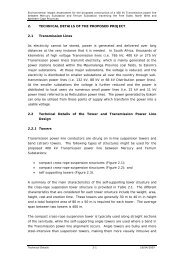
To obtain maximum utilisation of the solar irradiation various collectors are in use. The<br />
collector performance characteristics are shown in Figure 1. and illustrate the efficiencies<br />
of the main three types solar collectors use presently in South Africa, namely:<br />
standard non selective-coated flat-plate collectors<br />
selective coated flat-plate collectors<br />
evacuated glass tube collectors.<br />
From the graphs shown in Figure 1, it is evident that the different collectors should be used<br />
for different purposes, namely:<br />
The tested non-selective coated flat-plate glazed collectors perform poorly at high<br />
operating temperatures. Their normal operational temperatures are in the limits of<br />
30 – 80 o C, heat loss coefficient is above 5 W/m 2 .K, and optical efficiency of 0.8; thus<br />
the applications for these collectors are limited for domestic hot water.<br />
The tested selective coated flat-plate glazed collectors perform well at high<br />
operating temperatures. Their normal operational temperatures are in the limits of<br />
40 – 90 o C, heat loss coefficient is above 3 W/m 2 .K, and optical efficiency of 0.80.<br />
Thus the applications of this collectors is extended for domestic and commercial hot<br />
water large systems. The higher operational temperatures allow reducing the size<br />
of the collector when compared with non-selective coated collectors.<br />
8
Measurement and Verification Standard <strong>Guideline</strong> for Low Pressure <strong>Solar</strong> <strong>Water</strong> <strong>Heating</strong> Systems v1r1<br />
The tested evacuated tubes collectors have high operating temperatures, namely<br />
between 90 – 130 o C, heat loss coefficient is above 2 W/m 2 .K, and optical efficiency<br />
of 0.65. These collectors are ideal for space cooling and heating and for process<br />
heat.<br />
Figure 1:. Collector Output Efficiency Curves measured for several types of solar collectors<br />
available in South Africa as a function of (Tm – Ta ) where: Tm - average collector<br />
temperature and Ta - ambient temperature. Source [3]<br />
Low Pressure <strong>Solar</strong> <strong>Water</strong> Heater Roll-out as supported by ESKOM and the South African<br />
Government, initially will be based on mainly imported SWH systems [2]. According to the<br />
Energy Minister Ms. Dipuo Peters on the opening of the one of the first roll-outs at<br />
Winterveldt (Tshwane) , “the units installed there were imported, as would be the case with<br />
the first 200 000 units installed through the programme, as the country gears up its<br />
manufacturing capacity towards SWH” [2]. The SWH units installed at Winterfeldt were<br />
based on evacuated tubes collectors and should perform as shown in Figure 1. One could<br />
expect that the rest of systems installed initially will be similar.[5]<br />
3.2.2 Collector Orientation<br />
To achieve maximum performance of the SWH system the collector should be facing ideally<br />
in the equator i.e. in the North direction in South Africa. Roofs and houses position toward<br />
North does not always allow this rule to be observed. Deviations from North up to 45 0 will<br />
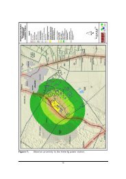
reduce the solar harvesting insignificantly (less than 10%). This is illustrated on the chart<br />
shown in Figure 2., where positioning of a house is shown. The size of the suns pointed at<br />
9
Measurement and Verification Standard <strong>Guideline</strong> for Low Pressure <strong>Solar</strong> <strong>Water</strong> <strong>Heating</strong> Systems v1r1<br />
the installation angle symbolizes the harvesting potential of the solar collector at different<br />
angle of deviation from the North.<br />
Figure 2: Orientation of the house’s roof for potential SWH system installation in respect to<br />
the North direction<br />
Prior to the installation of the collector, a study should be performed on the particular<br />
household to determine the profile of the hot water usage. If the bulk of the hot water to be<br />
used is between 10 a.m. and 2 p.m. the orientation of the collector should be North-East<br />
(NE). If the hot water is to be used after 2 p.m. the collector should be orientated in North<br />
West (NW) direction allowing longer harvesting of the solar energy during the afternoon<br />
hours. The orientation of the collector(s) in the above conditions is shown in Figure 3 to<br />
Figure 5.<br />
10
Measurement and Verification Standard <strong>Guideline</strong> for Low Pressure <strong>Solar</strong> <strong>Water</strong> <strong>Heating</strong> Systems v1r1<br />
Figure 3: Collector (s) orientation toward North-preferable positioning<br />
Figure 4: Collector (s) orientation toward North-East. Collector output is reduced slightly<br />
(less than 10%). Applicable when roof does not allow North orientation of the collector.<br />
Apply it when the bulk of the hot water is used before 2:00p.m.<br />
Figure 5: Collector (s) orientation toward North-West Collector output is reduced slightly<br />
(less than 10%). Applicable when roof does not allow North orientation of the collector.<br />
Apply it when the bulk of the hot water is used after 2:00p.m.<br />
11
Measurement and Verification Standard <strong>Guideline</strong> for Low Pressure <strong>Solar</strong> <strong>Water</strong> <strong>Heating</strong> Systems v1r1<br />
3.3 Influence of the Local Climatic Conditions on the SWH System<br />
Performance<br />
3.3.1 Climatic Zones in South Africa<br />
The performance of any SWH system is influenced in a great deal by the geographic location<br />
of the installation site and it is extremely seasonal. Thus, the actual installation site will be a<br />
dominant factor in the system thermal performance and related energy savings from the<br />
retrofit.<br />
The average annual solar energy potential per day is shown in Figure 6 and 7. It is evident<br />
that the South African solar potential could be simplified if the country is divided into six<br />
regions according to the availability of solar incoming energy as presented in Figure 8.<br />
Obviously, the same type of SWH system will perform differently if it is installed on different<br />
climatic regions.<br />
Figure 6: Southern Africa average annual solar energy potential per day in [ kWh/m 2 ]<br />
Source [8]<br />
12
Measurement and Verification Standard <strong>Guideline</strong> for Low Pressure <strong>Solar</strong> <strong>Water</strong> <strong>Heating</strong> Systems v1r1<br />
Figure 7: Southern Africa average annual incoming solar power potential per day<br />
in [ kW/m 2 ] Source [8]<br />
Figure 8: South Africa’s solar energy radiation zones<br />
13
Measurement and Verification Standard <strong>Guideline</strong> for Low Pressure <strong>Solar</strong> <strong>Water</strong> <strong>Heating</strong> Systems v1r1<br />
3.3.2 Evaluation of LPSWHS in respect of Installation Site Location and<br />
Climatic /Seasonal variations<br />
In order to evaluate the LPSWHS performance and to report it for each month of the year, a<br />
monthly assessment of the energy (hot water) output is necessary.<br />
This <strong>Guideline</strong> employs a weather simulation software Meteonorm ®. The software<br />
simulates the weather information for the different locations in South Africa and generates<br />
the necessary hourly profiles for the incoming solar radiation, ambient temperature for each<br />
day of the year. This information is incorporated into the Performance Model (PM) of the<br />
LPSWHS and the its performance is evaluated and reported as per ESKOM EA’s<br />
requirements.<br />
3.4 High Pressure and Low Pressure <strong>Solar</strong> <strong>Water</strong> Heaters<br />
Essentially, high and low-pressure solar water heating systems have a similar design and<br />
work on the same principles. However, the differences between the two are the pressures<br />
under which they operate in their normal cycle.<br />
3.4.1 High Pressure <strong>Solar</strong> <strong>Water</strong> Heaters<br />
High-pressure SWH are connected directly to the consumer’s water supply (mains) thus<br />
developing a very high internal tank pressure (in the region of 600kpa). This pressure is the<br />
main force that drives the water through the pipes resulting in high water pressure and<br />
flow from the taps, thus providing the desired hot water service level. In South Africa, as a<br />
rule the high-pressure SWH systems have an electric back-up element. A schematic basic<br />
drawing illustrating the operation of a High-pressure indirect thermo siphon SWH system is<br />
shown in Figure 9.<br />
A high-pressure system is required to be equipped with a number of protection and safety<br />
equipment in compliancy of the following standards SANS 60335-2-21 part2 (Electrical<br />
requirements), SANS198 (Functional control and safety valves for pressurized hot & cold<br />
water supply systems) & SANS 0254 The installation of fixed electric storage heating systems<br />
and SANS0142 code of practice the wiring of premises. [5]<br />
14
Measurement and Verification Standard <strong>Guideline</strong> for Low Pressure <strong>Solar</strong> <strong>Water</strong> <strong>Heating</strong> Systems v1r1<br />
Figure 8: Principle of operation of a High-pressure indirect thermo siphon SWH system<br />
3.4.2 Low Pressure <strong>Solar</strong> <strong>Water</strong> Heaters<br />
Low-pressure solar water heating systems in contrast to the High-pressure SWHs cannot<br />
tolerate the high pressures associated with their high-pressure counterparts and therefore<br />
have to be connected indirectly to the water supply through an additional system such as<br />
auxiliary (small) tanks that avoids the pressure rise in their main hot water storage tank.<br />
Basically, only limited pressure builds up in the low-pressure SWHs systems. Low-pressure<br />
solar water heating systems utilize the gravity to supply water through the piping system<br />
resulting in lower water pressures and associated low flows from the hot water outlets<br />
(taps). The principle of operation of a system employing an evacuate d tube solar collector<br />
is shown in Figure 10 and Figure 11.<br />
15
Measurement and Verification Standard <strong>Guideline</strong> for Low Pressure <strong>Solar</strong> <strong>Water</strong> <strong>Heating</strong> Systems v1r1<br />
Figure 10: Principle of operation of a LPSWS employing an evacuate d tube solar collector<br />
Figure 11: LPSWS employing evacuated tubes solar collector<br />
16
Measurement and Verification Standard <strong>Guideline</strong> for Low Pressure <strong>Solar</strong> <strong>Water</strong> <strong>Heating</strong> Systems v1r1<br />
Low pressure SWH systems can be equipped with an electric back-up element in a similar<br />
manner as the High-pressure SWH systems. However, for the purposes of this <strong>Guideline</strong><br />
which serves ESKOM’s Low Pressure <strong>Solar</strong> <strong>Water</strong> Heater Roll-out Programme the Lowpressure<br />
SWHs will be considered without any electrics back-element.<br />
4 LOW PRESSURE SOLAR WATER HEATING SYSTEMS AS<br />
RETROFIT PROJECTS OR AS GREENFIELD PROJECTS<br />
4.1 Retrofit projects<br />
These Projects are based on existing systems that are already in operation,<br />
and are either replaced with more energy efficient ones or operated in an altered<br />
fashion to deliver DSM impacts. The systems exist prior to the EEDSM intervention and<br />
allow for baseline metering [9].<br />
4.2 Greenfield Projects<br />
Greenfield Projects (also referred to as new construction projects) deals with systems that<br />
are not in operation at time of the EEDSM proposal [9].<br />
The proposed energy conservation measures for the DSM programme are consequently<br />
integrated into the design and construction of new systems. The systems do not exist to<br />
allow for baseline metering. [9]<br />
Thus, the fundamental difference between the M&V of Retrofit and Greenfield projects is<br />
related to the system baseline that is used as a reference point from which project impacts<br />
are determined.[9]<br />
4.3 Low Pressure <strong>Solar</strong> <strong>Water</strong> <strong>Heating</strong> Systems as Retrofit Projects<br />
Low Pressure <strong>Solar</strong> <strong>Water</strong> <strong>Heating</strong> EEDSM Projects could fall into the scope of the<br />
Greenfield Projects since the LPSWHS (or similar dedicated water heating unit ) did not exist<br />
before the retrofit . However, due to the M&V fundamental reporting methodology<br />
applicable the EEDSM projects, the projects are to be classified as Retrofit Projects. The<br />
main reason for this is the fact that prior the Retrofit, the projects had a base line<br />
determined by taking into account ONLY the electrical energy used for heating of water at<br />
the households prior the retrofit.<br />
5 TESTING OF LOW PRESSURE SOLAR WATER HEATING<br />
SYSTEMS.<br />
17
Measurement and Verification Standard <strong>Guideline</strong> for Low Pressure <strong>Solar</strong> <strong>Water</strong> <strong>Heating</strong> Systems v1r1<br />
5.1 Tests by South African Bureau of Standards (SABS)<br />
The Required Tests in Compliance with the relevant South African Standards for<br />
Supplying and Installing <strong>Solar</strong> <strong>Water</strong> Heater Systems in ESKOM’s SWH Program are given<br />
in Table 1.<br />
Table 1: Compulsory Tests in Compliance with South African Standards for Supplying<br />
and Installing <strong>Solar</strong> <strong>Water</strong> Heater Systems. Source ESKOM EA Package to M&V<br />
Teams.<br />
No SANS Number Description/ Title<br />
1 SANS 1307:2008 (SABS 1307) Residential solar water heaters<br />
2<br />
SANS 6210:1992<br />
(SABS SM 1210)<br />
3 SANS 6211-1: (or part 2) 2003<br />
4 SANS 60335-2-21: 2000<br />
Residential solar water heaters - Mechanical qualification<br />
tests<br />
Residential solar water heaters Part 1: Thermal performance<br />
using an outdoor test method (part 2 is an indoor test method)<br />
Safety of household and similar electrical appliances - Safety<br />
Part 1: General requirements<br />
5 SANS 151: 2002 Fixed Electrical storage water heaters<br />
6 SANS 10106: 2008<br />
7 SANS 10252-1:2004 <strong>Water</strong> drainage for buildings<br />
Note: SANS 60335 is compulsory under the building regulations at present<br />
The installation, maintenance, repair and replacement of<br />
domestic solar water heating systems<br />
5.2 Essential Information from SABS Test Reports Used to Determine the<br />
Performance of the Low Pressure <strong>Solar</strong> <strong>Water</strong> <strong>Heating</strong> Systems<br />
The results from the tests according to SANS 6211-1: (or part 2) 2003 are essential for<br />
evaluating of the thermal performance of the SWH systems.<br />
This <strong>Guideline</strong> aims to develop a performance evaluation model which uses the main SWH<br />
system parameters experimentally determined by the SABS tests as shown in Table 2.<br />
18
Measurement and Verification Standard <strong>Guideline</strong> for Low Pressure <strong>Solar</strong> <strong>Water</strong> <strong>Heating</strong> Systems v1r1<br />
Table 2: Essential parameters extracted from SABS Test Report<br />
No<br />
Parameter determined by Test<br />
Report according to: SANS 6211-<br />
1: (or part 2) 2003<br />
19<br />
Symbol<br />
Coefficient 1 m 2<br />
Units<br />
1<br />
2 Coefficient 2 MJ/K<br />
3 Coefficient 3 MJ<br />
4 Heat capacity of the tank Cs MJ/K<br />
5 Heat loss coefficient Us W/K<br />
6. Q-factor / value Q MJ<br />
Value as<br />
per SABS<br />
Test Report<br />
5.2.1 Examples based on extracts from a typical SABS Test Report Performed<br />
on LPSWHSs<br />
The following figures below show extracts from a SABS report and illustrate how to<br />
identify and select the important parameters needed to evaluate the thermal performance<br />
of the LPSWH systems. Note that, SABS is changing some of the conditions for the testing<br />
(for example for Q-factor/value) and the reports may differ from system to system.
Measurement and Verification Standard <strong>Guideline</strong> for Low Pressure <strong>Solar</strong> <strong>Water</strong> <strong>Heating</strong> Systems v1r1<br />
20
Measurement and Verification Standard <strong>Guideline</strong> for Low Pressure <strong>Solar</strong> <strong>Water</strong> <strong>Heating</strong> Systems v1r1<br />
Based on the above extracts from SABS test report, for this particular LPSWH system Table 2<br />
can be completed as shown in Table 3.<br />
21
Measurement and Verification Standard <strong>Guideline</strong> for Low Pressure <strong>Solar</strong> <strong>Water</strong> <strong>Heating</strong> Systems v1r1<br />
Table 3: Example of Essential parameters extracted form SABS Test Report for a typical<br />
LPSWHS<br />
No<br />
Parameter determined by Test<br />
Report according to: SANS 6211-<br />
1: (or part 2) 2003<br />
22<br />
Symbol<br />
Units<br />
Value as<br />
per SABS<br />
Test Report<br />
Coefficient 1 m 2 0.625150588<br />
1<br />
2 Coefficient 2 MJ/K -0.034373641<br />
3 Coefficient 3 MJ 2.114795133<br />
4 Heat capacity of the tank Cs MJ/K 307798.3<br />
5 Heat loss coefficient Us W/K 0.482<br />
6. Q-factor/value Q MJ 11.773<br />
5.3 Accuracy and Errors of the Tests at SABS<br />
As evident from the extracts from the SABS test reports the standard error when<br />
determining the LPSWH system coefficients is high (often more than the value of the<br />
coefficient itself). However, the M&V process will consider that these tests are justifiable<br />
since they are the corner stone for participation in ESKOM’s and Government SWH<br />
Programmes [1] and [2].<br />
6 BASELINE OF LOW PRESSURE SOLAR WATER HEATING<br />
PROJECTS<br />
6.1 Typical Site Description<br />
The LPSWHSs typically fall out in the rollout Programmes launched to the<br />
undeveloped communities. A typical such a site is shown in Figure 12.
Measurement and Verification Standard <strong>Guideline</strong> for Low Pressure <strong>Solar</strong> <strong>Water</strong> <strong>Heating</strong> Systems v1r1<br />
Figure 12: Typical installation site foe LPSWH Systems<br />
The living environment and the underdeveloped infrastructure make the installation and<br />
more over the safety for the M&V equipment and personnel very difficult. Individuals should<br />
therefore take the necessary care to avoid any incidences and/or damage to property.<br />
Electrical connections in the low-cost houses might be very unconventional and unsafe as<br />
evident from Figure 13.<br />
Figure 13: Electrical Installations at RDP Houses pose hazards for the inhabitants of the<br />
houses and M&V teams.<br />
23
Measurement and Verification Standard <strong>Guideline</strong> for Low Pressure <strong>Solar</strong> <strong>Water</strong> <strong>Heating</strong> Systems v1r1<br />
6.2 Electricity Usage Patterns in Low-cost Housing Environment<br />
6.2.1 Installed Electrical Appliances at a Typical Low-cost House<br />
Some typical electrical devices used in low-cost houses are shown in Figure 14.<br />
Figure 14. Typical low cost housing electrical appliances. Source [10]<br />
An audit [11] conducted in low-cost housing environment showed the following appliances<br />
and associated installed power as per Table 4.<br />
Table 4. Installed Power in a Typical Low-cost House . Source [[11]<br />
No<br />
Appliance<br />
Installed Power<br />
1 Fridge 133<br />
2 Kettle 1980<br />
3 Hot Plate 850<br />
4 TV 51<br />
5 DVD player 22<br />
6 Iron 1100<br />
7 Fan 150<br />
8 Space Heater 1500<br />
W<br />
24
Measurement and Verification Standard <strong>Guideline</strong> for Low Pressure <strong>Solar</strong> <strong>Water</strong> <strong>Heating</strong> Systems v1r1<br />
9 Incandescent lamps 600<br />
10 Total Installed Power 6386<br />
6.2.2 Electricity Usage and Load Profiles at Low-cost Housing Environment<br />
An end of winter, load profile in a low-cost housing environment (corresponding to Table 4<br />
above) is shown in Figure 15.<br />
Figure 15. Electrical Load Profile and Inside and Outside House Temperatures. Source [11].<br />
As seen from Figure 15, the load profile shown there contents electric water heating<br />
components in the morning, noon and evening.<br />
The load profile of the same house is shown in Figure 16, after the house was supplied with<br />
thermal ceiling insulation, solar water heating, solar cooker and LPG gas cooker.<br />
25
Measurement and Verification Standard <strong>Guideline</strong> for Low Pressure <strong>Solar</strong> <strong>Water</strong> <strong>Heating</strong> Systems v1r1<br />
Figure 16: Electrical Load Profile and Inside and Outside House Temperatures after the<br />
house was a subject of a sustainable “ makeover” where all major electrical appliances<br />
were replaced by sustainable alternatives. Source [11].<br />
From Figure 16 is evident that the electrical energy consumption for this particular house<br />
was reduced and the electricity is used for refrigeration, lighting and entertaining purposes<br />
only.<br />
Another study [10] investigated the Electrical energy consumption in a typical low-cost<br />
house and the results are shown in Table 5.<br />
Table 5. Installed Power and Electrical energy consumption in a typical low-cost house.<br />
Source[10]<br />
Appliance Qty<br />
CFL lights<br />
Incandescent<br />
Lights<br />
TV<br />
Kettle<br />
Rated<br />
Power<br />
Operating<br />
Hours per<br />
Day<br />
26<br />
kWh per<br />
Day<br />
Days<br />
kWh per<br />
Month<br />
3 16 6 0.288 30 8.64<br />
2 60 6 0.72 30 21.6<br />
1 80 4 0.32 30 9.6<br />
1 2000 1 2 30 60
Hotplate<br />
Iron<br />
Fridge<br />
TOTAL<br />
Measurement and Verification Standard <strong>Guideline</strong> for Low Pressure <strong>Solar</strong> <strong>Water</strong> <strong>Heating</strong> Systems v1r1<br />
1 850 2 1.7 30 51<br />
1 1000 1 1 30 30<br />
1 150 16 2.4 30 72<br />
4156 36 8.428 252.84<br />
From Table 5 is evident the eclectic energy used for water heating is about 2 kWh a day.<br />
Several energy audits were made by the authors of this <strong>Guideline</strong> and the results of<br />
auditing of 582 low-cost (RDP) houses are shown in Table 6 and Table 7.<br />
Table 6. Audits of Electrical <strong>Water</strong> <strong>Heating</strong> usage (before retrofit) and <strong>Solar</strong> <strong>Water</strong> <strong>Heating</strong><br />
Usage (after retrofit) at 582 houses at Tshwane area.<br />
Houses <strong>Solar</strong> <strong>Water</strong><br />
<strong>Heating</strong> Litres<br />
582.00<br />
83<br />
53<br />
154<br />
179<br />
113<br />
Litres<br />
Electric <strong>Water</strong> <strong>Heating</strong> up to the Boiling Point<br />
Morning Noon Evening<br />
Litres<br />
27<br />
Litres Litres<br />
5 436.70 726.10 244.40 565.85<br />
3 492.30 450.60 230.80 371.90<br />
10 803.88 1 466.30 318.20 1 004.81<br />
11 922.70 1 264.40 565.90 946.90<br />
9 907.48 1 188.80 190.66 641.80<br />
Totals<br />
41 563.06 5 096.20 1 549.96 3 531.26<br />
Total Litres Electrical <strong>Water</strong><br />
10 177.42<br />
<strong>Heating</strong> at Boiling Point<br />
Average Consumption per House in Litres<br />
71.41 17.49<br />
The results from Table 6 are used to determine the average electrical energy used to heat<br />
the water at the houses and the findings are summarised in Table 7.
Measurement and Verification Standard <strong>Guideline</strong> for Low Pressure <strong>Solar</strong> <strong>Water</strong> <strong>Heating</strong> Systems v1r1<br />
Table 7. Average Hot water usage heated by electricity at an average low-costs household<br />
Hot <strong>Water</strong> Usage by<br />
Electricity <strong>Heating</strong>.<br />
Total Houses<br />
interviewed 582<br />
Litres heated<br />
at 96 o C<br />
Energy<br />
Used<br />
l kWh<br />
28<br />
T C Thot Tcold Efficiency<br />
of heating<br />
o K kWh/kg.K<br />
o C<br />
o C %<br />
17.49 1.81 80 0.001167 96 16 90<br />
From the results and deliberations in sections 6.2.1 and 6.2.2. above, is evident that the<br />
average daily usage of hot water heated by electricity up to the boiling point could be<br />
summarised as follows:<br />
Volume of hot water in litres……………………………………………………………..17.49 l<br />
Electrical energy usage to boil this volume of water……………………………1.81 kWh<br />
6.3 Installation of Dedicated M&V Equipment at Project Sites<br />
Examples of data loggers installations are shown in Figures 17 and 18.<br />
Figure 17: Installation of dedicated SWH Data Logger at a RDP House
Measurement and Verification Standard <strong>Guideline</strong> for Low Pressure <strong>Solar</strong> <strong>Water</strong> <strong>Heating</strong> Systems v1r1<br />
Figure 18: Complete Installation of a dedicated SWH Data Logger at a RDP House<br />
6.4 Base Line Methodology<br />
As elaborated in Section 3.3. above the LPSWH systems will be treated as Retrofit Projects,<br />
thus the system (electric water heating at the houses) physically exist and can consequently<br />
be measured and monitored before it is altered by the EEDSM project (the installation of<br />
the LPSWHs). Thus, the base line is determined on the basis of hot water usage heated by<br />
ELECTRICITY ONLY i.e. what the grid would “see”.<br />
6.4.1 Base Line Main M&V Question<br />
The main M&V question when dealing with LPSWH projects is to identify the electricity<br />
consumption and its time of use to heat water prior the retrofit. This may be achieved by<br />
the following ways:<br />
By interviews with the inhabitants<br />
By dedicated SWH measurements after the retrofit<br />
By measurements of the electricity prior and after retrofit.<br />
6.4.2 Interviews with the inhabitants<br />
This method provides information on the following activities as summarised in Table 8.<br />
Table 8: Possible Information obtained by interviews by the occupants of the households.<br />
No Information Obtained Remarks<br />
1 Number of people living in the house (their profile:<br />
gender, age, working , unemployed, culture etc.)<br />
29<br />
Often people are giving misleading<br />
and inconsistent information. Also
Measurement and Verification Standard <strong>Guideline</strong> for Low Pressure <strong>Solar</strong> <strong>Water</strong> <strong>Heating</strong> Systems v1r1<br />
2 Establish how , when and how much and for what<br />
purpose water is heating by electricity.<br />
3 Establish the power in [kW] of the water heating device<br />
and evaluate the energy/demand used.<br />
The electrical water heating used at a low-cost<br />
household is based on average figures and often on the<br />
assumption that the water is heated by<br />
standard/conventional electric kettle with an typical<br />
installed power of 2 kW and a typical volume of 1.8<br />
litres. The cold water temperature may wary by the<br />
season and is taken as Tcold = 16 o C . The water is<br />
heated until boil i.e. Thot = 96 o C (it assumed that the<br />
kettle switches off automatically at that temperature).<br />
The heating process efficiency ( ) is taken as 90%<br />
which takes into account losses if the water is heated<br />
not by kettle but by hot plate for example. The thermal<br />
energy for each boil ( Ehw) is calculated by:<br />
)<br />
The corresponding electrical energy needed to produce<br />
this thermal energy is :<br />
4 Obtain information for electricity and water bills for<br />
the household for crosschecking the information<br />
above.<br />
30<br />
the actual number of people living<br />
at the house might vary.<br />
Urban households would use more<br />
electricity than the rural ones.<br />
1.This might be misleading since<br />
the households use predominantly<br />
prepaid electricity and when the<br />
balance is negative the inhabitants<br />
might use alternative means for<br />
heating water.<br />
2. It might be useful to assume that<br />
all the water heated electrically in<br />
a household is done by an<br />
”equivalent electric kettle “(2 kW)<br />
as it is in the majority of urban<br />
households. This would simplify<br />
the process of base line<br />
development. Note that, the water<br />
heated by the kettle for bathing,<br />
washing and cooking is always<br />
mixed with cold water in order to<br />
meet the volume and temperature<br />
needed.<br />
This might be grossly misleading<br />
since in most of the cases<br />
inhabitants do not provide<br />
accurate answers due to one<br />
reason or another.<br />
Note: An example for a typical house base line determination using interviews is given in section<br />
10 below.<br />
6.4.3 Using Base Line Measurements by Dedicated SWH data Loggers after<br />
the Retrofit<br />
The dedicated data loggers supplied by EA are shown in Figure 18 and 19.
Measurement and Verification Standard <strong>Guideline</strong> for Low Pressure <strong>Solar</strong> <strong>Water</strong> <strong>Heating</strong> Systems v1r1<br />
Figure 19: SWH Data Logger<br />
The measurements obtained by the data loggers installed after the retrofit do not provide<br />
correct information about base line hot water usage. The amount of hot water used after<br />
and before the retrofit is not the same. However, they could be used to determine the<br />
performance assessment evaluation.<br />
6.4.4 Measurements of the Electrical Energy prior and after Retrofit at the<br />
Household<br />
The most appropriate way is to measure the savings and determine the base line is to<br />
measure the electrical energy and determine the base line in combination with the<br />
interview as described in Section 5.3.2. above.<br />
Simple and inexpensive data loggers and CTs as shown in Figure 20 and Figure 21 could be<br />
used to measure the current at the household and thus to determine the savings in a way<br />
that the grid can “see” them. This will allow a precise measurements of time of use for<br />
electrical water heating appliances.<br />
Figure 20: A Current Transformer (CT) and its connection to a Data Logger is installed at a<br />
DB in a Low-cost House to determine the base line and energy savings by the retrofit.<br />
31
Measurement and Verification Standard <strong>Guideline</strong> for Low Pressure <strong>Solar</strong> <strong>Water</strong> <strong>Heating</strong> Systems v1r1<br />
Figure 21: A Hobo Data Logger installed at a DB in a Low-cost House to determine the base<br />
line and energy savings by the retrofit.<br />
It should be noted that, the field measurements after the retrofit will be misleading when<br />
taken after the installations of the LPSWHs. This is due to the fact that the households could<br />
use the electricity for other applications such as : refrigeration, entertainment etc.(in the<br />
same manner as in the CFL rollouts) and the fact that some hot water usages has been<br />
replaced by the LPSWH. On the other hand people get used to utilize hot water for different<br />
applications after the retrofit.<br />
6.4.5 Recommendations for Baseline Procedure<br />
The following methodology is recommended as a Standard <strong>Guideline</strong> for Baseline<br />
development for Low Pressure <strong>Solar</strong> <strong>Water</strong> <strong>Heating</strong> Systems:<br />
Perform interviews and fill the information as required in Fieldworker Form [6]. A<br />
typical form is shown at the worked example shown in Section 10.<br />
Identify representative houses in terms of number and profile of occupants and<br />
install data loggers (if and where appropriate ) to measure the electricity<br />
consumption prior the retrofit.<br />
Determine electrical energy and find out the time of its use for water heating,<br />
based on the information obtain above .<br />
7 DETERMINATION OF THE SAVINGS<br />
32
Measurement and Verification Standard <strong>Guideline</strong> for Low Pressure <strong>Solar</strong> <strong>Water</strong> <strong>Heating</strong> Systems v1r1<br />
7.1 M&V RECOMMENDED OPTION<br />
Option A [5] [6] is recommended as a Standard <strong>Guideline</strong> for determination of the savings<br />
resulting from implementation Low Pressure <strong>Solar</strong> <strong>Water</strong> <strong>Heating</strong> Systems.<br />
Option A recommends Retrofit Isolation: Key Parameter Measurement Savings are<br />
determined by field measurement of the key performance parameter(s) which is the<br />
current (power) and which define the energy use of the household under consideration.<br />
Parameters not selected for field measurement are estimated. These are the inputs to all<br />
the engineering calculations based on the interviews leading to determination the amount<br />
of electrically heated hot water used by the household.<br />
7.2 MAIN M&V QUESTION FOR DETERMINATION OF THE SAVINGS RESULTING FROM LOW<br />
PRESSURE SOLAR WATER HEATING SYSTEMS<br />
The Baseline is determined as: energy kWh and power W at its time of use, the amount of<br />
hot water in terms of volume (litres) and temperature ( o C). It is more convenient to use as a<br />
volume the amount of water mixed (heated water by electricity with cold water). This allow<br />
to have a realistic figure for the amount of hot water usage. This is explained in details in the<br />
worked example at Section 10 below.<br />
The base line should be compared with the thermal output in [kWh] of the Low Pressure<br />
<strong>Solar</strong> <strong>Water</strong> <strong>Heating</strong> Systems during the month of consideration. Thus the main M&V<br />
question on which the M&V practitioner should report is : “ Can or cannot the LPSWH<br />
system offset the energy in kWh which was determined as a baseline”?<br />
There are two possible scenarios to report the savings.<br />
7.2.1 Scenario 1: Baseline energy in [kWh] is less or at least equal to the<br />
retrofit (LPSWH system) energy output in [kWh]<br />
The maximum value of the energy savings that grid would “see” is the value of the baseline<br />
as per equation (1) :<br />
where:<br />
the grid “sees”<br />
when ...............(1)<br />
- is the energy in [kWh] saved and produced by the LPSWH system and which<br />
33
Measurement and Verification Standard <strong>Guideline</strong> for Low Pressure <strong>Solar</strong> <strong>Water</strong> <strong>Heating</strong> Systems v1r1<br />
-is the energy in [kWh] prior the retrofit<br />
-is the thermal energy in [kWh] produced by the retrofit (LPSWH system)<br />
In this case there might be excess of energy which is not to be reported as energy savings<br />
resulting from the retrofit , but should reported separately .<br />
7.2.2 Scenario 2: Baseline energy in [kWh] is higher or at least equal to the<br />
retrofit (LPSWH system) energy output in [kWh]<br />
The value of the energy savings that grid would “see” is the value of the retrofit energy<br />
output as per equation (2) :<br />
when ...............(2)<br />
7.2.3 Examples to illustrate the energy savings<br />
Example: Consider a house which has an average monthly base line determined as<br />
2.05 kWh per day. The months under consideration are February and July. The<br />
house is supplied by a Low Pressure <strong>Solar</strong> <strong>Water</strong> <strong>Heating</strong> system which has average<br />
monthly thermal outputs for these months of 4.13 kWh /day and 1.29 kWh/day<br />
respectively. Determine the savings which the grid would “see” for these months.<br />
Solution:<br />
(a) Savings for the month of February<br />
Use the Scenario 1 and apply the equation (1)<br />
ESAVINGS = 2.05 kWh to be reported in the M&V reports. The project performs 100 % .<br />
In addition there will excess of energy not to be reported Eexess = 4.13 – 2.05 = 2.07 kWh<br />
(b) Savings for the month of July<br />
Use the Scenario 2 and apply the equation (2)<br />
ESAVINGS = 1.29 kWh to be reported in the M&V reports<br />
The Project is underperforming by 0.76 kWh ( 0.76= 2.05 – 1.29)<br />
34
Measurement and Verification Standard <strong>Guideline</strong> for Low Pressure <strong>Solar</strong> <strong>Water</strong> <strong>Heating</strong> Systems v1r1<br />
8 THERMAL PERFORMANCE MODEL OF LOW PRESSURE SOLAR<br />
WATER HEATING SYSTEMS<br />
As seen in section 6.2. above to quantify the energy savings, the thermal performance of<br />
the LPSWH system need to be determined. The model is based on the relevant standards<br />
such as SANS 1307 and ISO 9459 [5 ] [7 ]. Note that the model thermal outputs will be<br />
seasonal and dependant on the installation location and its accuracy is based on the<br />
parameters determined by the SABS test.<br />
The model inputs and outputs are shown in Figure 22.<br />
Figure 22: Thermal Performance Model<br />
An example from the model run for a particular LPSWH system is shown in Figure 23.<br />
35
Measurement and Verification Standard <strong>Guideline</strong> for Low Pressure <strong>Solar</strong> <strong>Water</strong> <strong>Heating</strong> Systems v1r1<br />
Figure 23. Example of the Thermal Model run for a typical LPSWH system<br />
9 SUMMARY<br />
From the deliberations above the following findings could be summarised as a Standard<br />
<strong>Guideline</strong> for Low Pressure <strong>Solar</strong> <strong>Water</strong> <strong>Heating</strong> Systems.<br />
The LPSWH system Project should be considered as Retrofit Projects not as Green<br />
Field Projects<br />
M&V Option: Option A is suggested which recommends Retrofit Isolation: Key<br />
Parameter Measurement Savings are determined by field measurement of the key<br />
performance parameter(s) which is the current (power) and which define the<br />
energy use of the household (s) under consideration.<br />
Base Line determination: the energy used for electrical water heating of a<br />
household(s) is determined by : interviews, field measurements. Also the volume<br />
and the temperature of the hot water usage is identified.<br />
Energy saving determination is based on modelling of LPSWH system(s). The model<br />
uses as inputs: the parameters determined by test report by SABS, the installation<br />
location, the hot water usage and the day/ month under consideration. The model<br />
outputs are: hourly, daily, monthly thermal output in [kWh] of the LPSWH system<br />
and the temperature hot water produced.<br />
It is possible that in addition to the energy savings reported to be an excess of<br />
energy produced by the retrofit. This energy will be reported separately and will not<br />
be part of the savings that grid would “see”.<br />
36
Measurement and Verification Standard <strong>Guideline</strong> for Low Pressure <strong>Solar</strong> <strong>Water</strong> <strong>Heating</strong> Systems v1r1<br />
10 A WORKED EXAMPLE FOR DEVELOPMENT OF THE BASE LINE<br />
AND DETERMINATION OF THE ENERGY SAVINGS OF A LPSWH<br />
PROJECT<br />
The example below illustrates the process of quantifying of hot water usage when<br />
determining a Baseline prior installation of a LPSWH system at a typical low-cost household<br />
having four to five occupants. The LPSWH system and its specifications and SABS Reports<br />
findings are shown in Table 3 in Section 5.2.1. above. A photo of a typical LPSWH used for<br />
the example is shown in Figure 15.<br />
Hot <strong>Water</strong> Consumption and associated energy determination<br />
Table 9 below is populated from the results on the audits done for the particular house. The<br />
audit is based on the field worker form filled by the M&V team. A sample form is shown at<br />
the end of this example.<br />
Table 9: Example for Baseline calculations<br />
The process used in this example is based on the assumption that the hot water used by<br />
this particular household is heated by an “equivalent kettle” of 2 kW and capacity of 1.8<br />
litres. The water heated by the kettle for bathing, washing and cooking is mixed with cold<br />
water in order to meet the volume needed. Also the water usage for tea, coffee or cooking<br />
is ignored since it will be heated at the same rate by electricity after the installation of<br />
LPSWHs.<br />
Hot <strong>Water</strong> Usage by<br />
Electricity<br />
Litres Actual Energy T C Thot Tcold Efficiency<br />
Litres Used<br />
of heating<br />
l l kWh o<br />
K kWh/kg.K o<br />
C<br />
o<br />
C %<br />
MORNING 14.4 10.8 1.12 80 0.001167 96 16 90<br />
Morning cooking<br />
tea/coffee<br />
Morning bath/sanitation<br />
(average 4 persons X 1.8 l<br />
each)<br />
1.8 0 0.00 80<br />
37<br />
0.001167 96 16 90<br />
7.2 7.2 0.75 80 0.001167 96 16 90<br />
Morning washing (1 X 1.8 l) 1.8 1.8 0.19 80 0.001167 96 16 90<br />
Cooking (just hot water) 1.8 0 0.00 80 0.001167 96 16 90<br />
Others (babies, minor<br />
washings etc.)<br />
1.8 1.8 0.19 80 0.001167 96 16 90<br />
LUNCH 3.6 1.8 0.19 80 0.001167 96 16 90<br />
Lunch dishes washings 1.8 1.8 0.19 80 0.001167 96 16 90
Measurement and Verification Standard <strong>Guideline</strong> for Low Pressure <strong>Solar</strong> <strong>Water</strong> <strong>Heating</strong> Systems v1r1<br />
Lunch tea 1.8 0 0.00 80 0.001167 96 16 90<br />
EVENING 9 7.2 0.75 80 0.001167 96 16 90<br />
Evening cooking 1.8 0 0.00 80 0.001167 96 16 90<br />
Evening bath /sanitation 3.6 3.6 0.37 80 0.001167 96 16 90<br />
Evening dishes washing 1.8 1.8 0.19 80 0.001167 96 16 90<br />
Others 1 x 1.8 l 1.8 1.8 0.19 80 0.001167 96 16 90<br />
Total per day 27 19.8 2.05 Total Baseline energy is 2.05 kWh<br />
Mixing of Hot <strong>Water</strong><br />
The hot water of each kettle is mixed with cold water in a ratio of say 1:4 in order to be<br />
usable for bathing , washing etc. This process is illustrated in Figures 24 and 25.<br />
}<br />
1 Kettle<br />
Hot <strong>Water</strong><br />
1.8 l at 96 o C<br />
}<br />
4 Kettles<br />
Cold <strong>Water</strong><br />
4 x 1.8 =7.2 l<br />
at 16 o C<br />
Figure 24: Mixing of hot water boiled by a kettle with cold water in ration 1:4 for further<br />
usage by the household.<br />
38<br />
}<br />
1 Bucket<br />
Mixed <strong>Water</strong><br />
5 x 1.8 = 9 l<br />
at 33.78 o C
Measurement and Verification Standard <strong>Guideline</strong> for Low Pressure <strong>Solar</strong> <strong>Water</strong> <strong>Heating</strong> Systems v1r1<br />
11 11 11<br />
} 19.8<br />
l<br />
at 96 o C<br />
Figure 25: Mixing of hot water boiled by all kettles with cold water in ration 1:4 for further<br />
usage by the household. The Base Line or entire hot water consumption by the household<br />
per day is determined as: 99 litres at 33.78 o C.<br />
The calculation of the mixed hot water temperature is based on the equations from Table 8<br />
(row 3).<br />
The results are shown in Table 10.<br />
}<br />
79.2 l<br />
at 16 o C<br />
Running of the LPSWH Thermal Performance Model<br />
To determine the performance of the LPSWH system against the Base Line the performance<br />
model should be run.<br />
The inputs are as shown in Figure 26. The month under consideration is February. This<br />
month is chosen as a typical month for high performance of the SWH system. The model<br />
outputs are reflected in Table 10.<br />
39<br />
99 l<br />
At 33.78 o C
Measurement and Verification Standard <strong>Guideline</strong> for Low Pressure <strong>Solar</strong> <strong>Water</strong> <strong>Heating</strong> Systems v1r1<br />
Figure 26: Thermal Performance Model for the month of February<br />
To illustrate a low performance for the SWH system the month of July is used. The model<br />
outputs for the month of July are shown in Figure 27, and then the results are reflected in<br />
Table 10.<br />
Figure 27: Thermal Performance Model for the month of July.<br />
The Yearly Thermal Performance Model Report is shown in Figure 28 and then the results<br />
are reflected in Table 10.<br />
40
Measurement and Verification Standard <strong>Guideline</strong> for Low Pressure <strong>Solar</strong> <strong>Water</strong> <strong>Heating</strong> Systems v1r1<br />
Figure 28: Yearly Thermal Performance Model Report<br />
Table 10. Hot <strong>Water</strong> Usage Profile and Thermal Performance Model Comparison<br />
Hot <strong>Water</strong> (1 kettle) at 96 o C<br />
Litres of Cold <strong>Water</strong> at 16 o C<br />
( 4 kettles x 1.8 l) mixed with<br />
1kettle x 1.8 l (hot water at 96 o C)<br />
Litres per a<br />
kettle<br />
41<br />
Litres total Used<br />
a day<br />
1.80 19.80<br />
Kettles used<br />
per day<br />
11<br />
7.20 79.20 44<br />
Base Line<br />
Mixed <strong>Water</strong> total litres Base<br />
Line (used as an input to the<br />
Thermal Performance Model)<br />
99.00<br />
Temperature of the mixed water<br />
Base Line<br />
Electrical Energy used Base Line<br />
33.60<br />
[kWh]<br />
2.05<br />
Performance<br />
February July<br />
Annually *<br />
( per 365 Days)<br />
Model output per month [ kWh] 115.60 40.10 1184.81
Measurement and Verification Standard <strong>Guideline</strong> for Low Pressure <strong>Solar</strong> <strong>Water</strong> <strong>Heating</strong> Systems v1r1<br />
Model output per day [ kWh ] 4.13 1.29 3.246<br />
Model output hot water [ o C ] 59.65 39.11 52.1682<br />
Energy Balance as compared with<br />
the Base Line [ kWh ]<br />
2.07 -0.76 1.19<br />
Status of Performance<br />
over<br />
performing underperforming<br />
over<br />
performing<br />
Monthly Energy Savings [ kWh ]<br />
Energy Savings<br />
2.05 1.29 2.05<br />
*Note: The annual performance is given for reference only. The savings are reported<br />
on monthly basis.<br />
Savings Determination<br />
The savings are determined as comparison between the Base Line [kWh] and the<br />
performance [kWh] as verified by the Model for the months of February and July and are<br />
given in Table 5 above.<br />
Field Worker Form (sample)<br />
A typical such a form is shown below in Figure 29.<br />
42
Measurement and Verification Standard <strong>Guideline</strong> for Low Pressure <strong>Solar</strong> <strong>Water</strong> <strong>Heating</strong> Systems v1r1<br />
No Place:<br />
1.<br />
2.<br />
3.<br />
4.<br />
5.<br />
6.<br />
7.<br />
House Number<br />
<strong>Solar</strong> <strong>Water</strong> <strong>Heating</strong> System Type<br />
(tank Capacity Litres..................................................... )<br />
Roof / SWH System Orientation<br />
Estimate the angle of deviation of the collector axis from<br />
the NORTH Direction<br />
Number of people living in the house<br />
Estimate the amount of hot water in litres per day which is<br />
used at the household NOW after installation of the SWH<br />
Systems<br />
How the water was heated before the installation of the<br />
SWH Systems?<br />
How much is the monthly water bill of the household?<br />
One Kettle = 1.8 Litres , One bucket = 20 Litres K-kettle S-stove<br />
Figure 29. Typical Field Worker Form<br />
43<br />
N S E W<br />
NE<br />
NW<br />
SE<br />
Adults working M F<br />
Adults Pensioners M F<br />
Children older than<br />
6 years M F<br />
Children younger<br />
than 6 years M F<br />
For bathing (sanitation)<br />
total household<br />
For cooking<br />
For washing<br />
Electricity Litres:<br />
Paraphine Litres:<br />
Gas Litres:<br />
Firewood Litres:<br />
Other Litres:<br />
Rand<br />
Electrical <strong>Water</strong> <strong>Heating</strong> up to BOILING Point heated by Kettle (K) or Stove (S)<br />
morning morning morning midday evening evening evening<br />
Off peak standard peak standard peak standard Off peak<br />
00:00-06:00 06:00-07:00 07:00-10:00 10:00-18:00 18:00-20:00 20:00-22:00 22:00-00:00<br />
Litres Litres Litres Litres Litres Litres Litres<br />
K S K S K S K S K S K S K S<br />
SW
Measurement and Verification Standard <strong>Guideline</strong> for Low Pressure <strong>Solar</strong> <strong>Water</strong> <strong>Heating</strong> Systems v1r1<br />
11 REFERENCES<br />
[1]<strong>Eskom</strong> <strong>Solar</strong> <strong>Water</strong> <strong>Heating</strong> Programme<br />
http://www.eskomidm.co.za/residential/residential-technologies/solar-water-heatingprogramme-overview<br />
[2] Department of Energy http://www.energy.gov.za/files/swh_overview2.html<br />
[3] Dintchev OD Report to SANERI: INVESTIGATING THE BENEFITS OF DEVELOPMENT OF<br />
TECHNOLOGY FOR HIGH-PERFORMANCE SELECTIVE-COATED SOLAR WATER HEATING<br />
COLLECTORS December 2009<br />
[4] René Coetzee, Christo van der Merwe , LJ Grobler :THE MEASUREMENT AND<br />
VERIFICATION GUIDELINE: SOLAR WATER HEATING , July, 2007<br />
[5] SATS 50010:2010 Measurement and Verification of Energy Savings South African<br />
Standard<br />
[6] International Performance Measurement and Verification Protocol Concepts and<br />
Options for Determining Energy and <strong>Water</strong> Savings Volume 1, September 2010 Prepared<br />
by Efficiency Valuation Organization www.evo-world.org<br />
[7] International Standard ISO 9459 <strong>Solar</strong> <strong>Water</strong> <strong>Heating</strong>-Domestic <strong>Water</strong> <strong>Heating</strong><br />
Systems-Part 3: Performance tests for solar plus supplementary systems.<br />
[8] <strong>Solar</strong> Maps at http://www.solarfeedintariff.net/aficamap.html<br />
[9] Measurement and Verification <strong>Guideline</strong> for Greenfield DSM Projects, Version 2, 26<br />
March 2008<br />
[10] M.F. Manganye ,Prof O.D. Dintchev THE IMPACT OF SOLAR WATER HEATING<br />
TECHNOLOGY IN LOW COST HOUSING ENVIRONMENT AS ONE OF THE RENEWAL ENERGY<br />
OPTION TO REDUCE THE LOAD ON THE NATIONAL GRID Presented and published at the<br />
proceedings of the DUEE International Conference , 2009, Cape Town, South Africa.<br />
[11] Ognyan Dintchev, Georgie Donev, Adisa Jimoh GREEN LOW-COST HOUSES<br />
MAKEOVER AS A MAJOR PHASE TOWARDS SUSTAINABLE DEVELOPMENT IN SOUTH<br />
AFRICA Presented and published at the proceedings of the NORTH CAROLINA A & T STATE<br />
UNIVERSITY FIRST INTERNATIONAL CONFERENCE ON GREEN AND SUSTAINABLE<br />
TECHNOLOGY 17-19 November 2010 at GREENSBORO, NORTH CAROLINA, USA.<br />
44